


MATE3
System Display and Controller
Owner’s Manual

About OutBack Power Technologies
OutBack Power Technologies is a leader in advanced energy conversion technology. Our products include true sine wave inverter/chargers, maximum power point tracking charge controllers, and system communication components, as well as circuit breakers, batteries, accessories, and assembled systems.
Contact Information
Telephone: |
+1.360.435.6030 (North America) |
|
|
+1.360.618.4363 (Technical Support) |
|
|
+1.360.435.6019 (Fax) |
|
Mailing Address: |
OutBack Power Technologies |
Address: Sales, Marketing, & Warranty |
(North America) |
5917 – 195th Street N.E., #7 |
6115 – 192nd Street NE |
|
Arlington, WA 98223 USA |
Arlington, WA 98223 USA |
E-mail: |
Support@outbackpower.com |
|
Web Site: |
www.outbackpower.com |
|
Disclaimer
UNLESS SPECIFICALLY AGREED TO IN WRITING, OUTBACK POWER TECHNOLOGIES:
(a)MAKES NO WARRANTY AS TO THE ACCURACY, SUFFICIENCY OR SUITABILITY OF ANY TECHNICAL OR OTHER INFORMATION PROVIDED IN ITS MANUALS OR OTHER DOCUMENTATION.
(b)ASSUMES NO RESPONSIBILITY OR LIABILITY FOR LOSS OR DAMAGE, WHETHER DIRECT, INDIRECT, CONSEQUENTIAL OR INCIDENTAL, WHICH MIGHT ARISE OUT OF THE USE OF SUCH INFORMATION. THE USE OF ANY SUCH INFORMATION WILL BE ENTIRELY AT THE USER’S RISK.
Warranty Summary
OutBack Power Technologies Inc. warrants that the products it manufactures will be free from defects in materials and workmanship for a period of five (5) years subject to the conditions set forth in the warranty detail, found inside the back cover of this manual.
OutBack Power Technologies cannot be responsible for system failure, damages, or injury resulting from improper installation of their products.
Notice of Copyright
MATE3 System Display and Controller Owner’s Manual © November 2011 by OutBack Power Technologies. All Rights Reserved.
Trademarks
OutBack Power is a registered trademark of OutBack Power Technologies.
Date and Revision
November 2011, Revision C
Part Number
900-0117-01-00 Rev C
Important Safety Instructions
READ AND SAVE THESE INSTRUCTIONS!
This manual contains important safety instructions for the MATE3 System Display and Controller. Read all instructions and cautionary markings on the MATE3 and on any accessories or additional equipment included in the installation. Failure to follow these instructions could result in severe shock or possible electrocution. Use extreme caution at all times to prevent accidents.
Symbols Used
WARNING: Hazard to Human Life
This type of notation indicates that the hazard could be harmful to human life.
CAUTION: Hazard to Equipment
This type of notation indicates that the hazard may cause damage to the equipment.
IMPORTANT:
This type of notation indicates that the information provided is important to the installation, operation, and/or maintenance of the equipment. Failure to follow the recommendations in such a notation could result in voiding the equipment warranty.
Audience
This manual is intended for use by anyone required to install and operate this equipment. Be sure to review this manual carefully to identify any potential safety risks before proceeding. The operator should be familiar with all the features and functions of this equipment before proceeding. Failure to install or use this equipment as instructed in this manual can result in damage to the equipment that may not be covered under the limited warranty.
900-0117-01-00 Rev C |
1 |

Important Safety Instructions
Definitions
The following is a list of initials, terms, and definitions used in conjunction with this product.
|
Table 1 Terms and Definitions |
Term |
Definition |
|
|
AC |
Alternating Current; refers to voltage produced by the inverter, utility grid, or generator |
|
|
AGS |
Advanced Generator Start |
|
|
AUX |
Auxiliary switched relay or 12-volt output for OutBack devices |
|
|
Battery Monitor |
See FNDC. |
|
|
DC |
Direct Current; refers to voltage produced by the batteries or renewable source |
|
|
FCC |
Federal Communications Commission |
|
|
FNDC |
FLEXnet DC Monitor; battery monitor manufactured by OutBack Power. |
|
May be referred to as battery monitor |
|
|
FX-class |
A family of OutBack inverter products, such as the FX, VFX, GTFX, GVFX, and GFX models; |
|
used to differentiate them from Radian-class |
|
|
Grid-interactive, |
Utility grid power is available for use and the inverter is a model capable of returning |
grid-intertie, grid-tie |
(selling) electricity back to the utility grid |
|
|
HBX |
High Battery Transfer; a function of the MATE3 |
|
|
IEEE |
Institute of Electrical and Electronics Engineers; refers to a series of standards and |
|
practices for the testing of electrical products |
|
|
LED |
Light-Emitting Diode; refers to indicators used by the inverter and the system display |
|
|
MPP |
Maximum Power Point |
|
|
MPPT |
Maximum Power Point Tracking |
|
|
PV |
Photovoltaic |
|
|
Radian-class |
A family of Outback inverter products, such as the GS models; used to differentiate them |
|
from FX-class |
|
|
RTS |
Remote Temperature Sensor; accessory that measures battery temperature for charging |
|
|
SOC |
State of charge of a battery bank, usually as measured by a battery monitor |
|
|
System display |
Remote interface device (such as the MATE3), used for monitoring, programming and |
|
communicating with the inverter; also called “remote system display” |
|
|
Utility grid |
The electrical service and infrastructure supported by the electrical or utility company; |
|
also called “mains”, “utility service”, or “grid” |
|
|
2 |
900-0117-01-00 Rev C |
Important Safety Instructions
General Safety
WARNING: Limitations on Use
This equipment is NOT intended for use with life support equipment or other medical equipment or devices.
CAUTION: Equipment Damage
Only use components or accessories recommended or sold by OutBack Power
Technologies or its authorized agents.
IMPORTANT:
Do not attempt to install this equipment if it appears to be damaged in any way. See the Warranty section for instructions on returning the equipment.
Personal Safety
WARNING: Personal Injury
Use standard safety practices when working with electrical equipment. (Remove all jewelry, use insulated tools, wear cotton clothing, etc.)
Review the system configuration to identify all possible sources of energy. Ensure ALL sources of power are disconnected before performing any installation or maintenance on this equipment. Confirm that the terminals are de-energized using a validated voltmeter (rated for a minimum
1000 Vac and 1000 Vdc) to verify the de-energized condition.
WARNING: Fire Hazard
Do not operate the unit with damaged or substandard cabling.
CAUTION: Equipment Damage
Strictly enforce clearance requirements and keep all vents clear of obstructions that can inhibit air flow around or through the unit.
Sensitive electronics inside the equipment can be destroyed by static electricity. Be sure to discharge any static electricity built up before touching the equipment and wear appropriate protective gear.
Do not perform any servicing other than that specified in the installation instructions unless qualified to do so and have been instructed to do so by OutBack Power Technologies Technical Support personnel.
900-0117-01-00 Rev C |
3 |

Important Safety Instructions
Regulatory Specifications
See page 153 for all specifications and regulatory information, including certifications.
Required Resources
This product is required to be installed according to pertinent safety codes and standards. If installed in the United States, wiring practices must meet the requirements of the National Electrical Code (NEC). If installed in Canada, wiring practices must meet the requirements of the Canadian Electrical Code.
~National Electrical Code (NEC)/NFPA 70, Current Edition
~Canadian Electrical Code C22.1, Current Edition
Additional Resources
The following are references which may be used when installing this equipment. Depending on the nature of the installation, it may be highly recommended to consult any or all of these resources.
~National Electrical Code (NEC)/NFPA 70 Handbook, Current Edition
~UL 1741, Current Edition, Static Inverter and Charge Controllers for Use in Photovoltaic Power Systems
~International Building Code (IBC), Current Edition
~Photovoltaic Power Systems and the 2005 National Electrical Code: Suggested Practices
4 |
900-0117-01-00 Rev C |

Important Safety Instructions
Recycling Information
IMPORTANT: Recycle Electronics and Batteries
Batteries are considered hazardous waste and must be recycled according to local jurisdiction. Inverters and other electronics contain metals and plastics that should be recycled. The following websites and phone numbers provide additional information for recycling electronic products and batteries.
Earth 911, USA
Web site: http://www0H .Earth911.com
Address: 14646 N. Kierland Blvd., Suite 100
Scottsdale, AZ 85254
Phone: +1.480.337.3025 (direct)
OurEarth.org, USA
There is a place on the website for contacting OurEarth.org using email. No direct email address is provided.
Web site: http://www5H .ourearth.org
Address: P.O. Box 62133
Durham, NC 27715
Phone: +1.410.878.6485
Environmental Protection Agency, USA
Web site: http://www.epa.gov/wastes/conserve/materials/ecycling/donate.htm Address: EPA USA
Office of Resource Conservation and Recovery (5305P) 1200 Pennsylvania Avenue NW
Washington, DC 20460
Keep America Beautiful, USA
Web site: |
http://www.kab.org/ |
|
Email: |
info@kabH4 |
.org |
Address: |
1010 Washington Boulevard |
|
|
Stamford, CT 06901 |
|
Phone: |
+1.203.659.3000 (Main number) |
|
Fax: |
+1.203.659.3001 |
|
National Institute of Recyclers, Mexico
Web site: |
http://www.inare.org.mx/ |
|
Email: |
a57841279@prodigy.net.mx, margarita@inare6H |
.org.mx |
Phone: |
+1.55.57.85.9160 |
|
Fax: |
+1.55.57.84.1279 |
|
900-0117-01-00 Rev C |
5 |

Important Safety Instructions
Natural Resources Canada
Web site: |
http://www.nrcan-rncan.gc.ca/mms-smm/busi-indu/rec-rec-eng.htm |
Address: |
580 Booth |
|
Ottawa, ON K1A 0E8 |
Phone: |
+1.613.995.0947 |
TTY: |
+1.613.996.4397 |
|
(Phone and TTY: Monday to Friday, 8:30 a.m. to 4:30 p.m. ET) |
Office of Waste Management, Canada
Web site: http://wwwH8 .portaec.net/library/recycling/recycling_in_canada.html Address: Office of Waste Management
Conservation and Protection Environment Canada Ottawa, Ontario K1A 0H3
Phone: +1.819.997.2800
EuroRecycle.net, Europe
The following website provides general information about recycling in Europe. It also provides a list of companies and organizations that provide recycling information or assistance.
Web site: http://euro.recycle.net
E-mail: http://euroH9 .recycle.net/cgi-bin/feedback1.cgi?w=27
(This is an online form providing a means to contact the owners of the website.)
6 |
900-0117-01-00 Rev C |

Table of Contents |
|
Important Safety Instructions ............................................................................................. |
1 |
Symbols Used ................................................................................................................................................................................ |
1 |
Audience ......................................................................................................................................................................................... |
1 |
Definitions....................................................................................................................................................................................... |
2 |
General Safety ............................................................................................................................................................................... |
3 |
Personal Safety.............................................................................................................................................................................. |
3 |
Regulatory Specifications.......................................................................................................................................................... |
4 |
Required Resources..................................................................................................................................................................... |
4 |
Additional Resources .................................................................................................................................................................. |
4 |
Recycling Information ................................................................................................................................................................ |
5 |
Introduction...................................................................................................................... |
11 |
Purpose ......................................................................................................................................................................................... |
11 |
Functions...................................................................................................................................................................................... |
11 |
Features ........................................................................................................................................................................................ |
11 |
Installation........................................................................................................................ |
13 |
Parts List........................................................................................................................................................................................ |
13 |
Dimensions.................................................................................................................................................................................. |
13 |
Location Considerations......................................................................................................................................................... |
14 |
Mounting Considerations ...................................................................................................................................................... |
14 |
Mounting Options..................................................................................................................................................................... |
15 |
Installing the MATE3 ................................................................................................................................................................ |
16 |
Connecting the MATE3 ........................................................................................................................................................... |
17 |
Setting up Communication to the MATE3 ....................................................................................................................... |
22 |
Connecting a MATE3 Directly to a Computer............................................................................................................................... |
22 |
Connecting a MATE3 Indirectly to a Computer on a Network Switch ................................................................................. |
23 |
Connecting a MATE3 to a Computer Using a Router (internal to an intranet).................................................................. |
24 |
Connecting a MATE3 to a Computer Using a Router (external through the Internet)................................................... |
26 |
Operation ......................................................................................................................... |
29 |
Display and LED Status Indicators....................................................................................................................................... |
29 |
LED Status Indicators ............................................................................................................................................................................ |
30 |
Battery LEDs .................................................................................................................................................................................................................. |
30 |
Inverter LED (green) ................................................................................................................................................................................................... |
30 |
Charger LED (yellow) ................................................................................................................................................................................................. |
30 |
Generator LED (green)............................................................................................................................................................................................... |
31 |
Events LED (red)........................................................................................................................................................................................................... |
31 |
AC Input LED (yellow)................................................................................................................................................................................................ |
31 |
Favorite LED (green)................................................................................................................................................................................................... |
31 |
Displays ..................................................................................................................................................................................................... |
32 |
Power Up Screens ....................................................................................................................................................................................................... |
32 |
Home Screens............................................................................................................................................................................................................... |
33 |
Meter Bars................................................................................................................................................................................................................ |
33 |
Home Screen Types ............................................................................................................................................................................................. |
33 |
Basic Navigation ........................................................................................................................................................................ |
37 |
Soft Keys.................................................................................................................................................................................................... |
37 |
Inverter Input Select Soft Key (FX-class inverters only; Off Grid system type only)........................................................................... |
38 |
Grid Soft Key ................................................................................................................................................................................................................. |
39 |
900-0117-01-00 Rev C |
7 |

Table of Contents
Inverter Soft Key........................................................................................................................................................................................................... |
40 |
Warning Messages................................................................................................................................................................................................ |
42 |
Error Messages ....................................................................................................................................................................................................... |
43 |
Battery Soft Key ............................................................................................................................................................................................................ |
46 |
Charge Controller Soft Key....................................................................................................................................................................................... |
52 |
DataLog Screen...................................................................................................................................................................................................... |
53 |
Graph Screens......................................................................................................................................................................................................... |
54 |
Hot Keys ..................................................................................................................................................................................................... |
55 |
INVERTER Hot Key........................................................................................................................................................................................................ |
55 |
CHARGER Hot Key........................................................................................................................................................................................................ |
56 |
GENerator Hot Key ...................................................................................................................................................................................................... |
60 |
EVENTS Hot Key............................................................................................................................................................................................................ |
61 |
AC INPUT Hot Key ........................................................................................................................................................................................................ |
62 |
FAVORITE Hot Key ....................................................................................................................................................................................................... |
63 |
Controls and Navigation Keys .............................................................................................................................................. |
64 |
Removing the Front Cover .................................................................................................................................................................. |
64 |
Control Wheel.......................................................................................................................................................................................... |
65 |
Navigation Keys (buttons) ................................................................................................................................................................... |
66 |
Adjusting Set Points............................................................................................................................................................................... |
68 |
Programming ................................................................................................................... |
69 |
Types of Settings ....................................................................................................................................................................... |
70 |
Set Points...................................................................................................................................................................................... |
70 |
Access to the Main Menu ....................................................................................................................................................... |
71 |
Main Menu Structure ............................................................................................................................................................... |
72 |
Settings Menus .......................................................................................................................................................................... |
73 |
System Settings....................................................................................................................................................................................... |
73 |
System Information..................................................................................................................................................................................................... |
74 |
Save / Restore Configuration................................................................................................................................................................................... |
74 |
Saving a Configuration to an SD Card ........................................................................................................................................................... |
75 |
Restoring a Configuration from an SD Card ................................................................................................................................................ |
76 |
Firmware Version......................................................................................................................................................................................................... |
76 |
Date and Time............................................................................................................................................................................................................... |
77 |
LCD Display.................................................................................................................................................................................................................... |
77 |
Sound............................................................................................................................................................................................................................... |
78 |
Ethernet Addresses ..................................................................................................................................................................................................... |
78 |
Ethernet Ports ............................................................................................................................................................................................................... |
79 |
Data Stream ................................................................................................................................................................................................................... |
79 |
System Name ................................................................................................................................................................................................................ |
79 |
Installer Information ................................................................................................................................................................................................... |
80 |
Installer Settings........................................................................................................................................................................................................... |
80 |
Set User Access Level........................................................................................................................................................................................... |
80 |
Change Installer Password................................................................................................................................................................................. |
81 |
Challenge Installer Password ............................................................................................................................................................................ |
81 |
Inverter Settings...................................................................................................................................................................................... |
82 |
Search Menu.................................................................................................................................................................................................................. |
82 |
AC Input and Current Limit ...................................................................................................................................................................................... |
83 |
Grid AC Input Voltage Limits (FX-class only)...................................................................................................................................................... |
85 |
Gen AC Input Voltage Limits (FX-class only)...................................................................................................................................................... |
85 |
Grid AC Input Mode and Limits (Radian-class only)........................................................................................................................................ |
86 |
Gen AC Input Mode and Limits (Radian-class only) ........................................................................................................................................ |
87 |
AC Output....................................................................................................................................................................................................................... |
88 |
Low Battery .................................................................................................................................................................................................................... |
88 |
Battery Charger............................................................................................................................................................................................................. |
89 |
Battery Equalize............................................................................................................................................................................................................ |
89 |
Auxiliary Output (AUX Modes, FX-class only).................................................................................................................................................... |
90 |
Auxiliary Output (AUX Modes, Radian-class only) ........................................................................................................................................... |
93 |
Auxiliary Relay (AUX Modes, Radian-class only)............................................................................................................................................... |
96 |
Inverter Stacking.......................................................................................................................................................................................................... |
99 |
Grid-Tie Sell................................................................................................................................................................................................................. |
101 |
8 |
900-0117-01-00 Rev C |
Table of Contents
Calibrate ....................................................................................................................................................................................................................... |
102 |
Reset the Inverter to Factory Defaults............................................................................................................................................................... |
103 |
Charge Controller Settings ............................................................................................................................................................... |
104 |
Charger ......................................................................................................................................................................................................................... |
104 |
MPPT.............................................................................................................................................................................................................................. |
105 |
Temperature Compensation................................................................................................................................................................................. |
106 |
Battery Equalize ......................................................................................................................................................................................................... |
106 |
Grid-Tie Mode............................................................................................................................................................................................................. |
107 |
Auxiliary Output on the Charge Controller ..................................................................................................................................................... |
107 |
Aux Modes for the Charge Controller................................................................................................................................................................ |
108 |
Restart Mode............................................................................................................................................................................................................... |
110 |
Calibrate ....................................................................................................................................................................................................................... |
110 |
Reset Charge Controller to Factory Defaults................................................................................................................................................... |
111 |
Battery Monitor Settings.................................................................................................................................................................... |
112 |
Battery Setup .............................................................................................................................................................................................................. |
112 |
Shunt Enable............................................................................................................................................................................................................... |
112 |
FLEXnet Relay Mode ................................................................................................................................................................................................ |
113 |
FLEXnet Relay Set Points ........................................................................................................................................................................................ |
113 |
Reset FLEXnet DC to Factory Defaults............................................................................................................................................................... |
114 |
MATE3 Settings..................................................................................................................................................................................... |
115 |
Advanced Generator Start (AGS) Mode ............................................................................................................................................................ |
115 |
AGS Setup.............................................................................................................................................................................................................. |
116 |
AGS Functional Test........................................................................................................................................................................................... |
117 |
AGS Voltage Start ............................................................................................................................................................................................... |
118 |
AGS Load Start..................................................................................................................................................................................................... |
118 |
AGS State-of-Charge (SOC) Start................................................................................................................................................................... |
119 |
AGS Must Run Schedule................................................................................................................................................................................... |
119 |
AGS Quiet Time Schedule................................................................................................................................................................................ |
119 |
AGS Generator Exercise Schedule ................................................................................................................................................................ |
120 |
Set Generator Total Run Time........................................................................................................................................................................ |
121 |
AGS Timers............................................................................................................................................................................................................ |
121 |
Data Logging........................................................................................................................................................................................................ |
122 |
Data Log File Format ......................................................................................................................................................................................... |
123 |
High Battery Transfer (HBX)................................................................................................................................................................................... |
124 |
Grid Use Time ............................................................................................................................................................................................................. |
125 |
Charge Controller Float Coordination............................................................................................................................................................... |
127 |
Global Charger Output Control ........................................................................................................................................................................... |
127 |
FLEXnet DC Advanced Control ............................................................................................................................................................................ |
128 |
Reset MATE3 to Factory Defaults Screens........................................................................................................................................................ |
129 |
Configuration Wizard............................................................................................................................................................. |
130 |
Creating New Configurations .......................................................................................................................................................... |
130 |
Using Existing Configurations ......................................................................................................................................................... |
132 |
Restoring Configurations .................................................................................................................................................................. |
135 |
Applying the Profile to the System ................................................................................................................................................ |
137 |
Saving the Profile to an SD Card ..................................................................................................................................................... |
138 |
Device Data Logs..................................................................................................................................................................... |
139 |
Saving Data Logs for the FLEXmax Charge Controller ............................................................................................................ |
139 |
Saving Data Logs for the FLEXnet (FN) Battery Monitor......................................................................................................... |
140 |
Erasing Data Logs for the FLEXnet Battery Monitor................................................................................................................. |
141 |
Event Logs.................................................................................................................................................................................. |
142 |
To Save an Event Log.......................................................................................................................................................................... |
142 |
To Read an Event Log File from the SD Card .............................................................................................................................. |
143 |
To Delete an Event Log ...................................................................................................................................................................... |
144 |
Firmware Update..................................................................................................................................................................... |
145 |
Saving the Update to the SD Card.................................................................................................................................................. |
145 |
Installing the Firmware Update....................................................................................................................................................... |
147 |
Troubleshooting ............................................................................................................. |
149 |
Basic Troubleshooting of the MATE3............................................................................................................................... |
149 |
900-0117-01-00 Rev C |
9 |

Table of Contents
Event Messages........................................................................................................................................................................ |
150 |
Start and Stop Reasons for the AGS Function............................................................................................................... |
152 |
Specifications................................................................................................................. |
153 |
Mechanical Specifications.................................................................................................................................................... |
153 |
Regulatory Specifications..................................................................................................................................................... |
153 |
Firmware Revision................................................................................................................................................................... |
153 |
FCC Information to the User................................................................................................................................................ |
154 |
Menu Maps..................................................................................................................... |
161 |
Main Menu................................................................................................................................................................................. |
162 |
SETTINGS: System Menu Map (with User Access Levels)......................................................................................... |
163 |
SETTINGS: FX-class Inverter Menu Map (with User Access Levels)...................................................................... |
164 |
SETTINGS: Radian-class Inverter Menu Map (with User Access Levels) ............................................................. |
165 |
SETTINGS: Charge Controller Menu Map (with User Access Levels).................................................................... |
166 |
SETTINGS: FLEXnet DC Menu Map (with User Access Levels) ............................................................................... |
167 |
SETTINGS: MATE3 Menu Map (with User Access Levels).......................................................................................... |
168 |
Configuration Wizard............................................................................................................................................................. |
169 |
New Configurations............................................................................................................................................................................ |
169 |
Existing Configurations ..................................................................................................................................................................... |
170 |
Restoring Configurations.................................................................................................................................................................. |
171 |
Setup Complete Screen ........................................................................................................................................................ |
172 |
Device Data Logs..................................................................................................................................................................... |
173 |
FLEXmax Charge Controller Data Logs ........................................................................................................................................ |
173 |
FLEXnet DC Battery Monitor Data Logs ....................................................................................................................................... |
174 |
Event Logs.................................................................................................................................................................................. |
175 |
Product Registration ...................................................................................................... |
177 |
Warranty ........................................................................................................................ |
179 |
How to Arrange for Warranty Service .............................................................................................................................. |
180 |
Contacting OutBack............................................................................................................................................................................ |
180 |
Troubleshooting .................................................................................................................................................................................. |
180 |
Return Material Authorization (RMA)............................................................................................................................................ |
180 |
Returning Product to OutBack ........................................................................................................................................................ |
181 |
Out of Warranty .................................................................................................................................................................................................. |
181 |
Index.............................................................................................................................. |
183 |
10 |
900-0117-01-00 Rev C |

Introduction
Purpose
A renewable energy system requires some combination of inverter/chargers, batteries, charge controllers, and a renewable energy power source, as well as often interfacing with a generator. All of these components need to be adjusted and monitored for optimum performance. The MATE3 System Display and Controller (MATE3) provides that ability to monitor and program each OutBack component.
Functions
IMPORTANT:
The MATE3 is not intended for use with 32-volt inverters.
Specifically, the MATE3:
Communicates with FX Series inverters and Radian Series inverters, as well as OutBack charge controllers.
Coordinates system operation, maximizes performance, and prevents multiple products from conflicting with each other.
Permits adjustments to individual products and to the overall power system, including battery charging. Four different levels of access prevent users from changing settings that could potentially damage or disrupt the system.
~Switches among different components
~Views the status of each component
~Programs individual elements in the system, and also programs system-wide functions
Programs when an inverter connects to an AC source based on time, battery voltage, or time-of-day grid usage.
Signals a two-wire generator using the Advanced Generator Start (AGS) mode based on voltage, load, time of day, and the state of charge of the batteries.
Controls auxiliary AC or DC loads such as cooling fans and relays.
Links up to ten OutBack Inverter/Chargers and FLEXmax charge controllers. (An OutBack HUB10 Communications Manager is required.)
Issues a global Bulk or Equalize (EQ) charging command for both the inverters and charge controllers. (An OutBack HUB Communications Manager is required.)
Features
The MATE3 include the following features:
Six-line graphical LCD display screen for information display
Four “soft” keys and six “hot” keys for navigation and programming
Two navigation keys (UP and TOP) for moving through the menu maps for each device
One PORT key for selecting devices connected to the HUB ports
One LOCK key to lock access levels to prevent unauthorized changes to settings
Circular, touch-sensitive control wheel with a button in the center
One SD memory card slot (up to 4 GB)
Communication protocol: proprietary OutBack multidrop network
Interconnecting cable: CAT5 (8 IATIA 518B) PC noncrossover network cable (6 ft/1.8m)
Maximum tested cable length: 300 feet (100 m) of cable in an office/commercial building
Computer interface: system monitoring through (read-only) capabilities through a network
900-0117-01-00 Rev C |
11 |
Introduction
|
Battery Status LEDs (x3) |
LCD Screen |
|
|
|
INVERTER Hot Key |
|
EVENTS Hot Key |
|
Event LED (Red) |
|
|
|
|
Inverter Status LED (Green) |
|
|
|
|
SD Memory Card |
CHARGER Hot Key |
|
AC INPUT Hot Key |
|
|
|
Charger Status LED (Yellow) |
|
AC Status LED (Yellow) |
|
|
|
GEN(erator) Hot Key |
|
FAVORITE Hot Key |
GEN Status LED (Green) |
|
Favorite Status LED (Green) |
|
|
|
Soft Keys (x4) |
|
|
TOP Navigation |
|
UP Navigation Key |
Key |
|
|
LOCK Key |
|
PORT Navigation Key |
|
|
Control Wheel |
Center Button |
|
Back View
Side View
SD
Memory
Card Slot
Ethernet Port |
HUB or OutBack |
|
Device |
Network Status LEDs |
|
Figure 1 MATE3 Features
12 |
900-0117-01-00 Rev C |
Installation
Parts List
The following items are included with the MATE3 System Display and Controller:
MATE3 (with front cover)
SD memory card 1
6-foot CAT5 noncrossover cable
Silicon grease pack
MATE3 System Display and Controller Owner’s Manual (this manual)
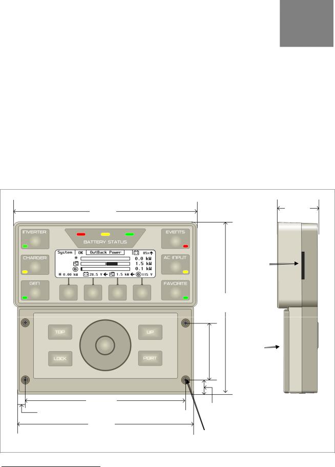
Dimensions
7 ½ ”
(19 cm)
6 5/8” 5/16” (16.8 cm)
0.79 cm)
7 ¼ ”
(18.4 cm)
1 5/8 ”
(4.2 cm)
SD Card
Slot
7 1/6”
(17.9 cm)
|
|
Front |
|
2 3/8” |
|||
|
Cover |
||
(6 cm) |
|
||
|
|
|
Side View
9/16” (1.4 cm)
Mounting Holes (x4)
Figure 2 MATE3 Dimensions
1 Size may vary depending on availability.
900-0117-01-00 Rev C |
13 |

Installation
Location Considerations
The following information is important to consider when installing the OutBack MATE3:
The MATE3 is intended for indoor installations only. Installing the MATE3 outdoors could expose it to damaging environmental conditions. Such damage is not covered by the limited warranty.
Readability of the display is affected by direct sunlight. It should be positioned about eye level for easier viewing and access.
The MATE3 voltage is less than 30 Vdc and is thus considered a “limited energy” circuit normally requiring no conduit. Cable runs must be protected and runs must be in approved conduit when conditions require. Consult the local inspector for specific installation requirements.
IMPORTANT:
Signal degradation can result if cable is run in conduit with AC wiring or in other electrically “noisy” environments; these can affect the maximum length the cable can run without incurring transmission errors.
Mounting Considerations
The MATE3 includes one 6-foot CAT5 cable. When working with CAT5 cables considering the following best practices:
CAT5 cable is not as strong as standard house wiring and must be handled carefully. Avoid kinking the cable or tearing its outer sheathing.
Use plastic standoff cable staples, J-hooks, or cable trays to support long runs of CAT5 cable. Do not splice cables.
14 |
900-0117-01-00 Rev C |
Installation
Mounting Options
Mounting bracket kits are sold as accessories for the MATE3 to accommodate different types of installations. These include kits for flat mounting, surface mounting, and FLEXware mounting. Follow the installation instructions included with each bracket for mounting the MATE3.
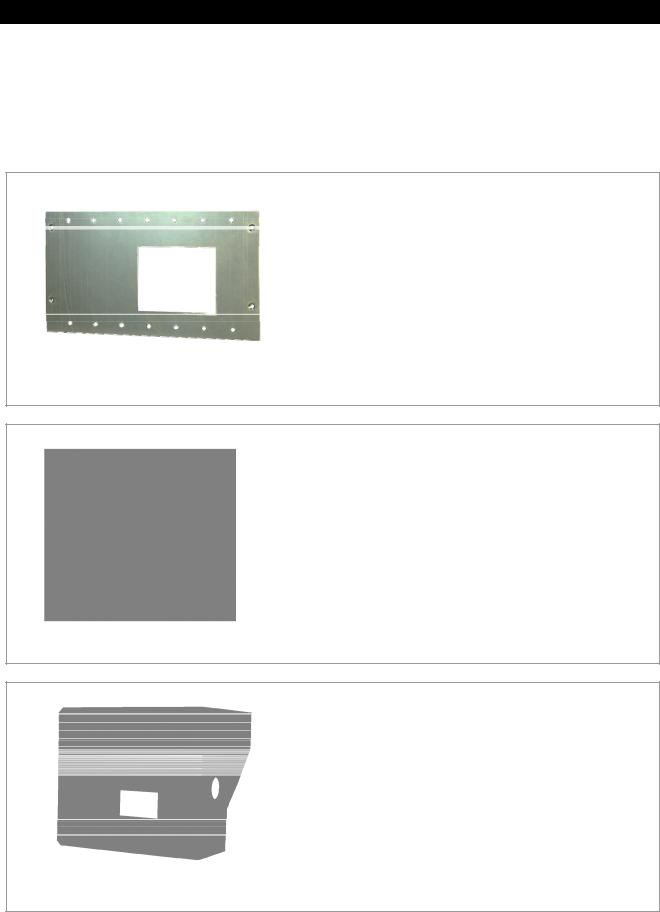
The MATE3 Flat Mount Kit (FW-MB3-F) is used for mounting the
MATE3 flat against a wall surface. It consists of a flat mounting plate.
It requires that an electrical outlet box (not provided) be installed in the wall to allow space for the CAT5 cables protruding out of the back of the MATE3. The CAT5 cable is then run through the wall into the electrical outlet box to the MATE3. The MATE3 mounts to the plate with the cable recessed into the wall.
Figure 3 MATE3 Flat Mount Kit (FW-MB3-F)
The MATE3 Surface Mount Kit (FW-MB3-S) is used for mounting the MATE3 to a flat surface, but doesn’t require any holes in the surface to accommodate the CAT5 cable. It consists of a bracket that holds the MATE3 away from the surface to allow clearance for the CAT5 cable.
Figure 4 MATE3 Surface Mount Kit (FW-MB3-S)
The FLEXware MATE3 Mounting Bracket (FW-MB3) is intended for mounting the MATE3 to a FLEXware assembly, either a FLEXware 1000 or FLEXware 500 AC Enclosure. It is also intended to mount the MATE3 directly to a Radian-class inverter.
Figure 5 MATE3 FLEXware Mount Kit (FW-MB3)
900-0117-01-00 Rev C |
15 |

Installation
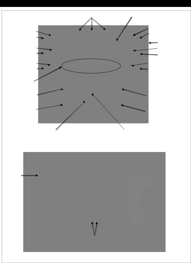
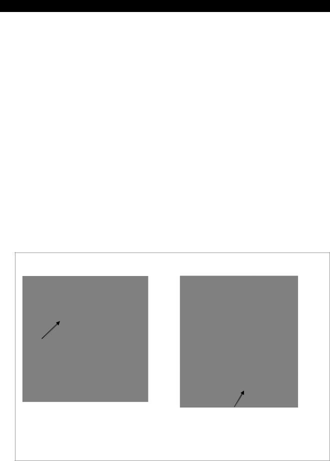
Transparent view from the front
To install the MATE3 without a mounting bracket:
1.To allow room for the CAT5 cables protruding out the back of the MATE3, cut a hole in the mounting surface that is 1-1/2" (height) by 2" (width), approximately 1-5/8" from the right edge and 1-3/8" up from the bottom.
2.Place the MATE3 on the wall with the cables inside the hole and mark the mounting holes by pushing a long nail into the mounting holes and putting a leader hole in the surface.
NOTE: Do not use a nail that is larger than the mounting screws.
Figure 6 Mounting the MATE3 without a Bracket
Installing the MATE3
The MATE 3 has several options for installation.
The MATE3 can be connected directly to an OutBack Inverter/Charger.
The MATE3 can be connected directly to a FLEXmax Charge Controller.
The MATE3 can be connected to a HUB4 or HUB10 Communication Manager when other OutBack devices are used in the system, such as charge controllers or multiple inverters.
In addition, the MATE3 can be connected to a computer (for monitoring only). This feature uses an online web page to provide a graphic user interface (GUI) for monitoring information on the system. See page 22 for details on this feature. The GUI cannot be used to change settings. The MATE3 can be connected to a computer in one of three ways:
directly (i.e., MATE3 to computer [requires a crossover CAT5 cable], or
MATE3 to network switch to computer [does not require a crossover CAT5 cable]),
using a network router (i.e., MATE3 to router to computer), or
using a wireless adapter connecting through a network router with wireless capabilities.
IMPORTANT:
Connecting the MATE3 to a computer or network router requires advanced knowledge of network protocols and how to manually set IP addresses and port forwarding.
Installing multiple OutBack devices requires the use of the HUB4 or HUB10 Communication Manager.
The MATE3 cannot operate with a FLEXnet DC Battery Monitor without an inverter, charge controller, or HUB product in the configuration.
16 |
900-0117-01-00 Rev C |
Installation
Connecting the MATE3
With the location and mounting options determined, choose one of the options in the previous section and prepare the location accordingly. Follow the instructions below to connect the wiring to the components based on the specific installation. Use the illustrations to identify cable placement.
MATE3 directly to an inverter or charge controller. See Figure 7.
MATE3 to HUB Communications Manager that connects to an inverter and a charge controller. See Figure 8.
MATE3 to a HUB Communications Manager with stacked (multiple) inverters. See Figure 9. (This configuration can also be used for multiple charge controllers.)
MATE3 to a HUB Communications Manager and directly to a computer. See Figure 10.
MATE3 to a HUB Communications Manager and indirectly to a computer through a network switch. See Figure 11.
MATE3 to a HUB Communications Manager directly to a network router that connects to a computer. See Figure 12.
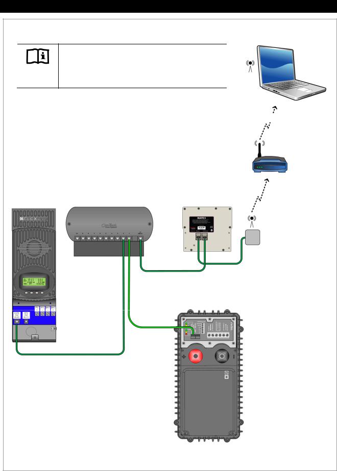
MATE3 to a HUB Communications Manager indirectly to a network router with wireless capabilities. See Figure 13. See IMPORTANT note on page 16 about this configuration.
To connect the MATE3:
1.Locate the position for the MATE3. Prepare the mounting surface according to the type of mounting chosen.
2.Run the CAT5 cable from the source (HUB, inverter, or charge controller) to the MATE3’s location. Connect the CAT5 cable to the source.
3.Connect the CAT5 cable to the MATE3 and secure it to the mounting bracket or surface.
|
OutBack |
FLEXmax Charge |
|
MATE3 (Back View) |
|||
Inverter/Charger |
Controller |
||
|
|
|
CAT5 Cable |
MATE3 (Back View) |
|
NOTE: |
CAT5 Cable |
|
The MATE3 can be connected to an MX60 Charge Controller, but only monitoring features will be available. The MATE3 will not be able to program the MX60.
Figure 7 Direct Connections to the MATE3 (no HUB)
900-0117-01-00 Rev C |
17 |
Installation
FLEXmax Charge |
OutBack HUB |
|
|
Communication Manager |
MATE3 (Back View) |
||
Controller |
|||
|
|
CAT5 Cable
OutBack
Inverter/Charger
CAT5 Cable
CAT5 Cable
To program the settings for the system on the MATE3, see the Programming section of this manual.
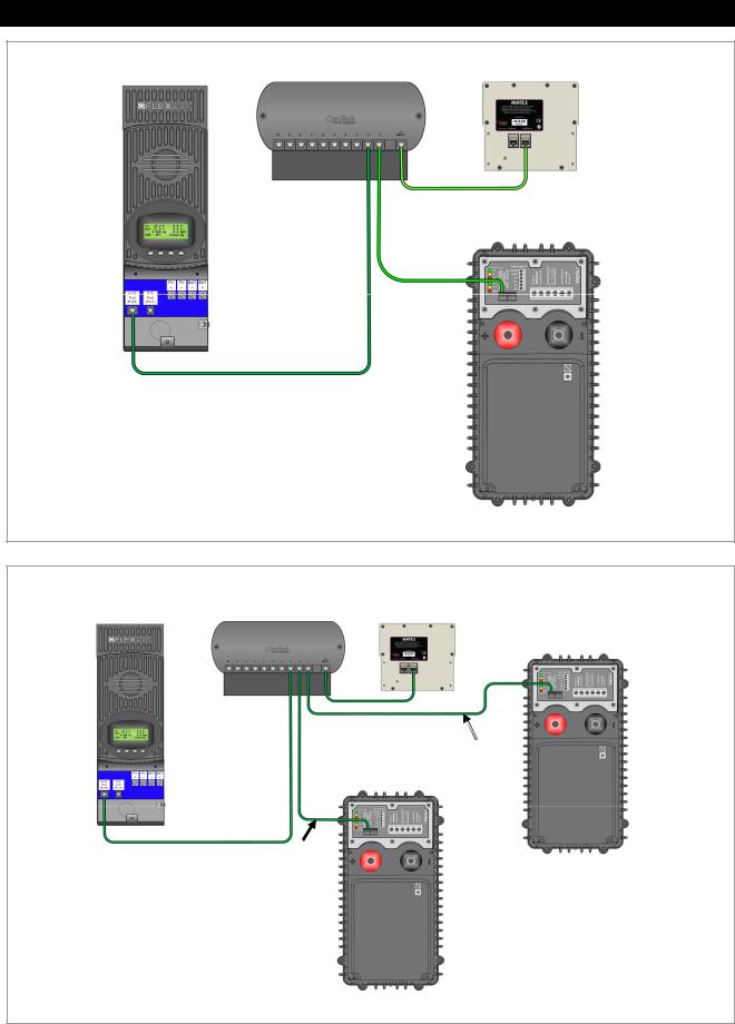
Figure 8 MATE3 Connections using a HUB Communication Manager
|
OutBack HUB |
|
|
|
FLEXmax Charge |
Communication |
MATE3 (Back View) |
OutBack |
|
Controller |
Manager |
|||
|
|
|
|
Inverter/Charger |
|
|
|
|
(Master) |
|
|
CAT5 |
|
|
|
|
Cable |
|
|
|
|
OutBack |
CAT5 |
|
|
|
Inverter/Charger |
Cable |
|
|
|
(Slave) |
|
|
CAT5 Cable
CAT5
Cable
To program the settings for the system on the MATE3, see the Programming section of this manual.
Figure 9 MATE3 Connections for Stacked Inverters
18 |
900-0117-01-00 Rev C |

Installation
|
OutBack HUB |
|
|
Communication |
|
FLEXmax Charge |
||
Manager |
||
Controller |
||
|
||
|
|
CAT5 Cable
For instructions on how to access the MATE3 web page on a computer, see page 22 .
MATE3 (Back View)
CAT5 Cable
CAT5 Cable
OutBack
Inverter/Charger
Computer
IMPORTANT:
DHCP must be disabled. A static IP address will be set on the computer and the MATE3.
This connection may require a CAT5 crossover cable. Some modern computers may be able to perform the crossover function even if a noncrossover cable is used. (The Ethernet chipset must support auto-switching.)
If this is not the case, then a network switch or router must be used. See Figure 11.
Figure 10 MATE3 Connections to a Computer (Direct)
|
OutBack HUB |
|
|
|
FLEXmax Charge |
Communication |
|
|
|
Manager |
MATE3 (Back View) |
|
|
|
Controller |
|
Computer |
||
|
|
|
Network |
|
|
|
|
Switch |
|
|
|
|
CAT5 |
|
|
|
CAT5 Cable |
Cable |
|
|
|
CAT5 Cable |
|
|
CAT5 |
OutBack |
|
Cable |
||
Inverter/Charger |
||
|
CAT5 Cable
For instructions on how to access the MATE3 web page on a computer, see page 22 .
IMPORTANT:
DHCP must be disabled. A static IP address will be set on the computer and the MATE3.
Figure 11 MATE3 Connections to a Computer (Using a Network Switch)
900-0117-01-00 Rev C |
19 |
Installation
Computer with
Wireless Adapter
IMPORTANT:
Connecting the MATE3 to a computer or network router requires advanced knowledge of network protocols and how to manually set IP addresses and port forwarding.
|
OutBack HUB |
|
|
FLEXmax Charge |
Communication |
MATE3 (Back View) |
|
Manager |
|||
Controller |
|||
|
|
Network
Router with
Wireless
Capabilities
CAT5 Cable
CAT5 Cable
OutBack
Inverter/Charger
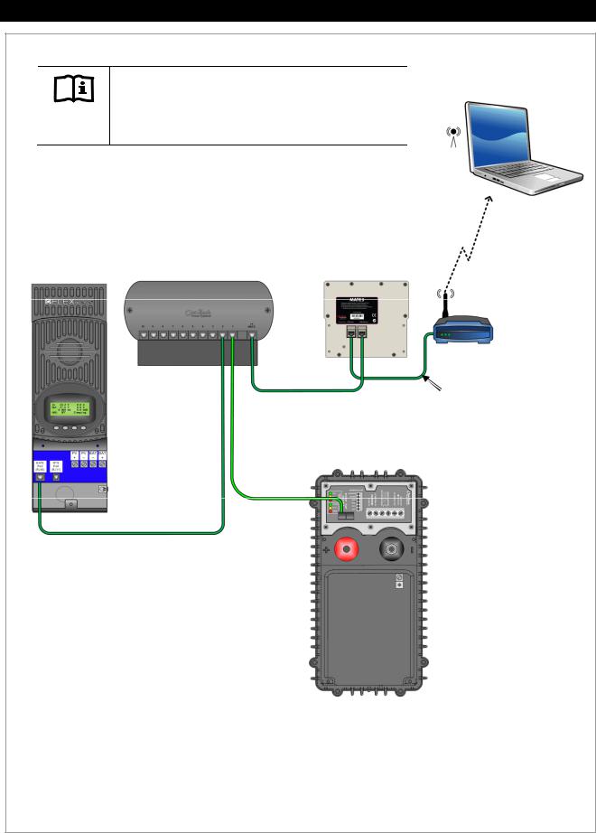
IMPORTANT:
CAT5 Cable |
DHCP must be enabled. |
CAT5 Cable
For instructions on how to set up the MATE3 and router to access the MATE3 web page on a computer, see page 24.
Figure 12 MATE3 Connections to a Computer (Using a Network Router)
20 |
900-0117-01-00 Rev C |
Installation
IMPORTANT:
Connecting the MATE3 to a computer or network router requires advanced knowledge of network protocols and how to manually set IP addresses.
For an INTERNET Connection:
DHCP must be disabled.
Static IP addresses must be set.
Port forwarding must be enabled and set.
For an INTRANET Connection:
DHCP must be enabled.
|
OutBack HUB |
|
FLEXmax Charge |
Communication |
|
Controller |
Manager |
MATE3 (Back View) |
CAT5 Cable
CAT5 Cable
OutBack
Inverter/Charger
CAT5 Cable
CAT5 Cable
Computer with
Wireless Adapter
by way of Internet
Network
Router with
Wireless
Capabilities
Universal
Wireless
Wi-Fi Adapter
Adapter
For instructions on how to set up the MATE3 and router to access the MATE3 web page on a computer, see page 24.
Figure 13 MATE3 Connections to a Computer (Wireless-to-Wireless)
900-0117-01-00 Rev C |
21 |
Installation
Setting up Communication to the MATE3
IMPORTANT:
Use either Mozilla Firefox® or Google Chrome® browsers to view the MATE3 web page on a personal computer. Internet Explorer® may not work properly.
Connecting a MATE3 Directly to a Computer
To access the MATE3 web page directly from the MATE3, follow the instructions below.
REQUIREMENTS:
MATE3 configured for network communication (see Programming section)
A computer with networking enabled
Mozilla Firefox® or Google Chrome® internet browser
Recommended Browsers |
Not Compatible |
Firefox® |
Chrome® |
Internet Explorer® |
To enable the MATE3 to communicate directly with a computer:
1.Make the connections illustrated in Figure 10.
2.On the computer, open a browser window.
3.In the address bar of the browser, type in the number 192.168.0.64 and press the ENTER key.
Address Bar
Figure 14 Accessing the MATE3 Directly Using a Computer
22 |
900-0117-01-00 Rev C |
Installation
Connecting a MATE3 Indirectly to a Computer on a Network Switch
To access the MATE3 web page using a network switch, follow the instructions below.
REQUIREMENTS:
MATE3 configured for network communication (see Programming section)
A computer with networking enabled
Mozilla Firefox® or Google Chrome® internet browser
Recommended Browsers |
Not Compatible |
Firefox® |
Chrome® |
Internet Explorer® |
To enable the MATE3 to communicate with a computer connected to a network switch:
1.Make the connections illustrated in Figure 11. Ensure the computer has a static IP address (for example, 192.168.0.63). Ensure it has the same netmask and gateway IP as the MATE3.
2.Ensure no other components on the network use the IP address 192.168.0.64. If there are other components with that same IP address, then the MATE3's IP address must be changed.
See page 78 for instructions on changing the MATE3's IP address.
3.On the computer, open a browser window.
4.In the address bar, type in the number 192.168.0.64. (Or if the MATE3's IP address was changed, type in the new number.)
Address Bar
Figure 15 Accessing the MATE3 Using a Computer on a Network Switch
900-0117-01-00 Rev C |
23 |
Installation
Connecting a MATE3 to a Computer Using a Router (internal to an intranet)
IMPORTANT:
Connecting the MATE3 to a computer or network router requires advanced knowledge of network protocols.
To access the MATE3 web page using a router that is connected to an internal intranet, follow the instructions below.
REQUIREMENTS:
MATE3 configured for network communication (see Programming section)
A computer with networking enabled
A universal wireless adapter for the MATE3 (optional)
Mozilla Firefox® or Google Chrome® internet browser
Access to a router with wireless capabilities
To enable the MATE3 to communicate with a computer connected to a router on an intranet:
1.Make the connections illustrated in Figure 12 or Figure 13.
On the MATE3:
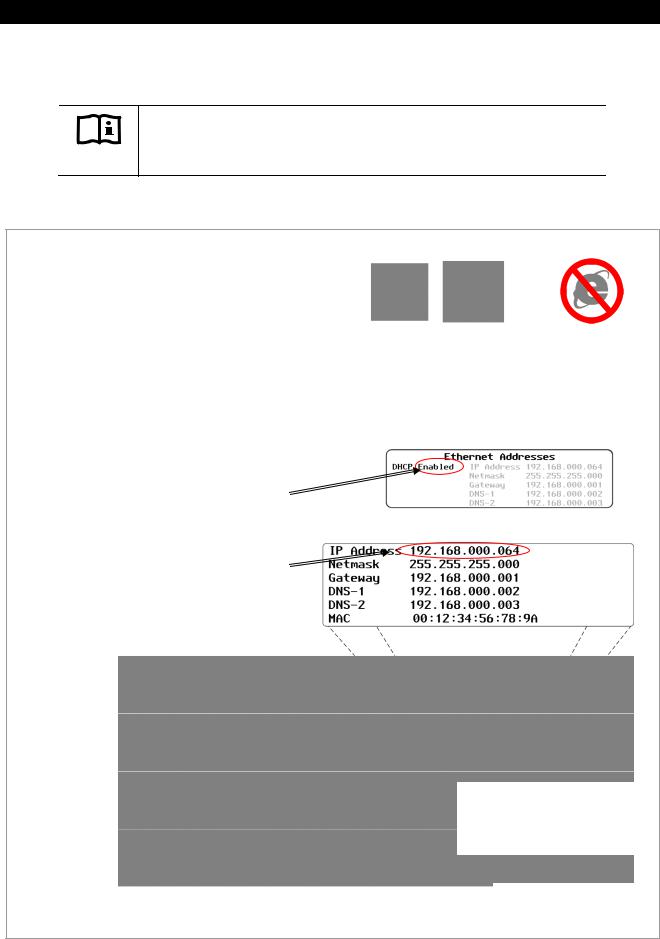
2.Go to the Ethernet Addresses screen in the MATE3 System Settings and ENABLE DHCP.
3.Press the center button on the control wheel to set these changes on the MATE3.
4.Identify the IP address assigned to the MATE3. To determine what the IP address is, press the <PORT> key from the Home screen.
Recommended Browsers |
Not Compatible |
Firefox® |
Chrome® |
Internet Explorer® |
See Programming on page 78 for instructions on accessing the System Settings on the MATE3.
See the manufacturer's instructions for setting up the router.
Home Screen
NOTE:
The IP address shown in this example may vary from the actual IP address assigned by the router.
Continued on next page….
Figure 16 Setting up the MATE3 to use a Router on an Intranet
24 |
900-0117-01-00 Rev C |

Installation
…continued from previous page.
On the computer:
To access the MATE3 web page:
1.Open a browser window.
2.In the address bar, type in the IP address.
Do not include any spaces. (For example: 192.168.0.64)
3.Press the Enter key on the computer keyboard.
Address Bar
Figure 16 Setting up the MATE3 to use a Router on an Intranet (continued)
900-0117-01-00 Rev C |
25 |
Installation
Connecting a MATE3 to a Computer Using a Router (external through the Internet)
IMPORTANT:
Connecting the MATE3 to a computer or network router requires advanced knowledge of network protocols and how to manually set IP addresses and enabling port forwarding.
To access the MATE3 web page using a router through the internet, follow the instructions below.
REQUIREMENTS:
MATE3 configured for network communication (see Programming section)
A computer with networking enabled
A universal wireless adapter for the MATE3 (optional)
Mozilla Firefox® or Google Chrome® internet browser
Access to a router with wireless capabilities
Advanced knowledge of establishing static IP addresses and enabling port forwarding in both the router and on the MATE3
To enable the MATE3 to communicate with a computer connected to a router:
1.Make the connections illustrated in Figure 12 or Figure 13.
On the MATE3:
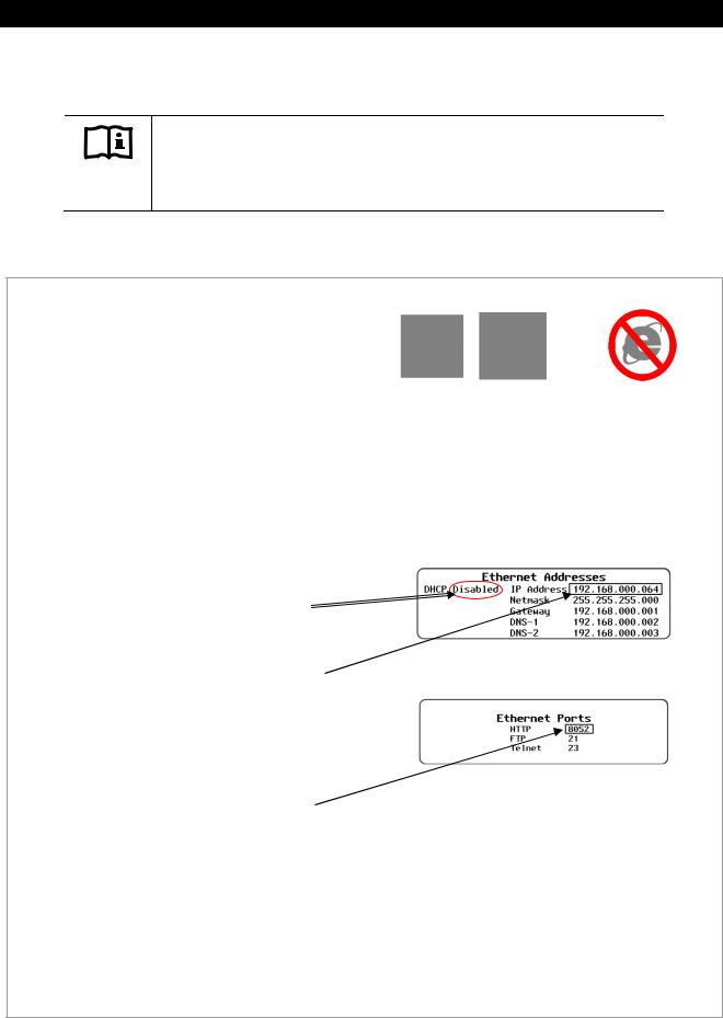
2.Go to the Ethernet Addresses screen in the MATE3 System Settings and DISABLE DHCP.
3.Change the IP Address, Netmask, Gateway, and DNS-1 to the appropriate numbers for the network (DNS-2 is optional). Ensure these numbers are unique on the network. If any other component has the same numbers, this will NOT work.
4.Write these numbers down for use later in these instructions.
5.Go to the Ethernet Ports screen and change the HTTP port to any number above 8000 , but no higher than 64000 (for example, 8052). If an FTP port or Telnet port is to be used, then change those settings to the appropriate number as provided by the network administrator. If not, do not change them.
6.Press the center button on the control wheel to set these changes on the MATE3.
Recommended Browsers |
Not Compatible |
Firefox® |
Chrome® |
Internet Explorer® |
See Programming on page 78 for instructions on accessing the System Settings on the MATE3.
See the manufacturer's instructions for setting up the router.
Continued on next page….
Figure 17 Setting up the MATE3 to use a Router on the Internet
26 |
900-0117-01-00 Rev C |
Installation
…continued from previous page.
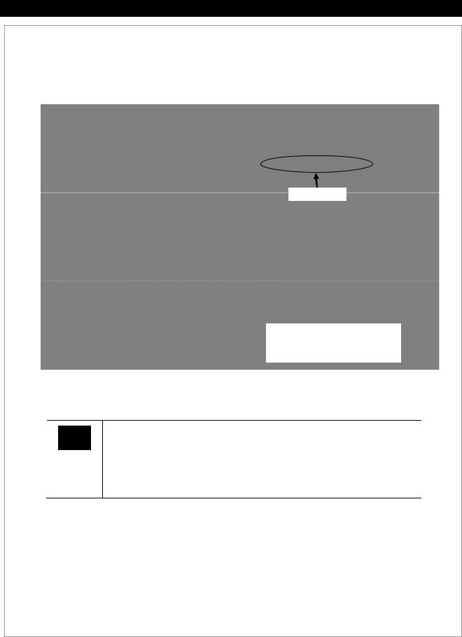
7.Identify the MAC address assigned to the MATE3. This will be a unique number for each MATE3 (for example, 00:12:34:56:78:9A). Every MATE3 will have a different MAC address. To determine what the MAC address is, press the <PORT> key from the Home screen.
MAC Address
Press the <PORT> key to display the
IP Address, Netmask, DNS-1,
DNS-2 (if used), and MAC address.
On the router's setup page:
IMPORTANT:
Router setup pages will vary by manufacturer. Consult the manufacturer's documentation for the router in use for specific instructions on making the following settings. Computers will need a hardwired connection to the router to access the router's setup page). After setup is complete, the hardwired connection to the router can be removed.
8.Set a static IP address, netmask, and DNS-1 for the router. Setting DNS-2 is optional.
9.Bind the MAC address of the MATE3 to the IP address set in the MATE3 on the router. See above to identify the MAC address for the MATE3. This will be a unique nu mber for each MATE3.
10.Enable port forwarding on the router.
11.Assign the MATE3’s IP address to the designated port (e.g., 8052).
Continued on next page….
Figure 17 Setting up the MATE3 to use a Router on the Internet (continued)
900-0117-01-00 Rev C |
27 |

Installation
…continued from previous page.
On the computer:
To access the MATE3 web page:
1.Open a browser window.
2.In the address bar, type in the IP address, followed by a colon, then the port number. Do not include any spaces. (For example: 192.168.xxx.xxx:xxxx)
3.Press the Enter key.
Address Bar
Figure 17 Setting up the MATE3 to use a Router on the Internet (continued)
28 |
900-0117-01-00 Rev C |
 Loading...