


FLEXMAX 80

FLEXmax Series
Charge Controllers
(FLEXmax 80, FLEXmax 60)
Owner’s Manual

About OutBack Power Technologies
OutBack Power Technologies is a leader in advanced energy conversion technology. Our products
include true sine wave inverter/chargers, maximum power point tracking charge controllers, and
system communication components, as well as circuit breakers, batteries, accessories, and
assembled systems.
Contact Information
Address: Corporate Headquarters
17825 – 59
Suite B
Arlington, WA 98223 USA
Telephone:
Email: Support@outbackpower.com
Website: http://www.outbackpower.com
+1.360.435.6030
+1.360.618.4363 (Technical Support)
+1.360.435.6019 (Fax)
th
Avenue N.E.
European Office
Hansastrasse 8
D-91126
Schwabach, Germany
+49.9122.79889.0
+49.9122.79889.21 (Fax)
Disclaimer
UNLESS SPECIFICALLY AGREED TO IN WRITING, OUTBACK POWER TECHNOLOGIES:
(a) MAKES NO WARRANTY AS TO THE ACCURACY, SUFFICIENCY OR SUITABILITY OF ANY TECHNICAL
OR OTHER INFORMATION PROVIDED IN ITS MANUALS OR OTHER DOCUMENTATION.
(b) ASSUMES NO RESPONSIBILITY OR LIABILITY FOR LOSS OR DAMAGE, WHETHER DIRECT, INDIRECT,
CONSEQUENTIAL OR INCIDENTAL, WHICH MIGHT ARISE OUT OF THE USE OF SUCH INFORMATION. THE
USE OF ANY SUCH INFORMATION WILL BE ENTIRELY AT THE USER’S RISK.
Notice of Copyright
FLEXmax Series Charge Controllers Owner’s Manual © July 2013 by OutBack Power Technologies. All
Rights Reserved.
Trademarks
OutBack Power and the OutBack Power logo are trademarks owned and used by OutBack Power
Technologies, Inc. The ALPHA logo and the phrase “member of the Alpha Group” are trademarks
owned and used by Alpha Technologies Inc. These trademarks may be registered in the United States
and other countries.
Date and Revision
July 2013, Revision C
Part Number
900-0009-01-00 Rev C

Table of Contents
Introduction ................................................................................................................................................................. 5
Features .................................................................................................................................................................................................... 5
Firmware ................................................................................................................................................................................................... 5
Soft Keys ................................................................................................................................................................................................... 6
Installation .................................................................................................................................................................... 7
Standards and Requirements ............................................................................................................................................................ 7
Grounding .......................................................................................................................................................................................... 7
DC and Battery-Related Installation Requirements .............................................................................................................. 7
Dimensions .............................................................................................................................................................................................. 8
Mounting the Charge Controller ...................................................................................................................................................... 9
Wiring ...................................................................................................................................................................................................... 10
Wire and Disconnect Sizing ........................................................................................................................................................ 10
FLEXmax 80 ................................................................................................................................................................................ 10
FLEXmax 60 ................................................................................................................................................................................ 10
Wiring Compartment .................................................................................................................................................................... 11
Operation .................................................................................................................................................................... 15
Power Up Screens ................................................................................................................................................................................ 15
Version and/or Voltage Setting Screens................................................................................................................................. 16
Status Screen ................................................................................................................................................................................... 17
End-of-Day Summary Screen ..................................................................................................................................................... 18
Navigating the End-of-Day Screens and Data Logging .................................................................................................... 19
Modes of Operation ............................................................................................................................................................................ 20
Absorbing ......................................................................................................................................................................................... 20
Auto Start (Auto ReStart) ............................................................................................................................................................. 21
BatTmpErr ......................................................................................................................................................................................... 21
BatTooHot ........................................................................................................................................................................................ 21
Charged ............................................................................................................................................................................................. 21
EQ ........................................................................................................................................................................................................ 21
EQ Done ............................................................................................................................................................................................ 21
EX-Absorb ......................................................................................................................................................................................... 22
Floating ............................................................................................................................................................................................. 22
GT Mode ............................................................................................................................................................................................ 22
High Voc ............................................................................................................................................................................................ 22
Low Light or Snoozing ................................................................................................................................................................. 22
MPPT Bulk ......................................................................................................................................................................................... 22
MPPT Float ........................................................................................................................................................................................ 22
MPPT EQ ............................................................................................................................................................................................ 23
New Voc ............................................................................................................................................................................................ 23
OvrCurrent ........................................................................................................................................................................................ 23
Over Temp ........................................................................................................................................................................................ 23
Re-Cal ................................................................................................................................................................................................. 23
Sleeping ............................................................................................................................................................................................ 23
Sys Error ............................................................................................................................................................................................. 23
Tracking ............................................................................................................................................................................................. 23
Unloaded .......................................................................................................................................................................................... 24
Wakeup.............................................................................................................................................................................................. 24
Zzzzz... ................................................................................................................................................................................................ 24
Initial Operation ................................................................................................................................................................................... 24
900-0009-01-00 Rev C 1

Table of Contents
Changing the Settings on the FLEXmax ...................................................................................................................................... 24
Accessing the Main Menu ........................................................................................................................................................... 24
Main Menu Map .............................................................................................................................................................................. 25
Charger Screen .......................................................................................................................................................................... 26
Aux Screens ................................................................................................................................................................................ 27
AUX MODE Screen Navigation ............................................................................................................................................. 29
Vent Fan (AUX Mode) ........................................................................................................................................................ 30
PV Trigger (AUX Mode) ..................................................................................................................................................... 31
Error Output (AUX Mode) ................................................................................................................................................ 32
Night Light (AUX Mode) ................................................................................................................................................... 33
Float (AUX Mode) ............................................................................................................................................................... 34
Diversion (AUX Mode) ....................................................................................................................................................... 35
Low Battery Disconnect (AUX Mode)........................................................................................................................... 40
Remote (AUX Mode) .......................................................................................................................................................... 41
Backlight ...................................................................................................................................................................................... 41
EQ – Battery Equalize .............................................................................................................................................................. 42
Misc Screen ................................................................................................................................................................................. 44
Advanced Menu ........................................................................................................................................................................ 46
Snooze Mode (Advanced Menu) ................................................................................................................................... 46
Wakeup Mode (Advanced Menu) ................................................................................................................................ 47
MPPT Mode (Advanced Menu) ...................................................................................................................................... 47
Absorb Time Limits (Advanced Menu) ........................................................................................................................ 49
Absorb End Amps (Advanced Menu) ........................................................................................................................... 49
Rebulk Voltage (Advanced Menu) ................................................................................................................................ 50
Vbatt Calibration (Advanced Menu)............................................................................................................................. 50
RTS Compensation (Advanced Menu) ......................................................................................................................... 50
Auto ReStart (Advanced Menu) ..................................................................................................................................... 52
Aux Polarity (Advanced Menu) ...................................................................................................................................... 53
Reset to Defaults? ............................................................................................................................................................... 53
Logging ....................................................................................................................................................................................... 54
Stats .............................................................................................................................................................................................. 55
Viewing the Firmware Revision ................................................................................................................................................. 56
Extended Play Mode ..................................................................................................................................................................... 56
Rebooting the FLEXmax .............................................................................................................................................................. 57
MATE3 System Display and Controller ............................................................................................................ 59
Display and LED Status Indicators.................................................................................................................................................. 59
Charge Controller Soft Key .................................................................................................................................................... 60
DataLog Screen ................................................................................................................................................................... 61
Graph Screens ...................................................................................................................................................................... 62
Menu Structure in the MATE3 ......................................................................................................................................................... 63
Charge Controller Settings ............................................................................................................................................................... 64
Charger .............................................................................................................................................................................................. 64
MPPT ................................................................................................................................................................................................... 64
Temperature Compensation ...................................................................................................................................................... 65
Battery Equalize .............................................................................................................................................................................. 65
Grid-Tie Mode.................................................................................................................................................................................. 65
Auxiliary Output (Charge Controller) ...................................................................................................................................... 66
Aux Modes for the Charge Controller ............................................................................................................................... 66
Restart Mode .............................................................................................................................................................................. 67
Calibrate ...................................................................................................................................................................................... 68
Reset Charge Controller to Factory Defaults ................................................................................................................... 68
Device Data Logs ................................................................................................................................................................................. 69
Saving Data Logs for the FLEXmax Charge Controller ...................................................................................................... 69
Data Log File Format ......................................................................................................................................................... 70
MATE/MATE2 Screens ............................................................................................................................................ 71
2 900-0009-01-00 Rev C

Table of Contents
Summary Screens ................................................................................................................................................................................ 71
Status Screens ....................................................................................................................................................................................... 72
MODE Screens ................................................................................................................................................................................. 72
METER Screens ................................................................................................................................................................................ 73
SETPT Screens ................................................................................................................................................................................. 74
LOG Screens ..................................................................................................................................................................................... 75
STAT Screens ................................................................................................................................................................................... 76
Advanced Menus ................................................................................................................................................................................. 77
Accessing the Advanced Menus ............................................................................................................................................... 77
CHGR Menu ...................................................................................................................................................................................... 78
CC ADVANCED Menu .................................................................................................................................................................... 79
EQ Menu ............................................................................................................................................................................................ 80
AUX Menu ......................................................................................................................................................................................... 81
MATE and MATE2 Menu Maps for the FLEXmax ....................................................................................................................... 82
STATUS Menu Map ........................................................................................................................................................................ 82
Advanced Menu Map ................................................................................................................................................................... 84
Menu Maps for the FLEXmax .............................................................................................................................. 87
Troubleshooting ...................................................................................................................................................... 91
Specifications ............................................................................................................................................................ 93
Electrical and Mechanical Specifications ..................................................................................................................................... 93
Firmware Revision ............................................................................................................................................................................... 93
Regulatory Specifications ................................................................................................................................................................. 93
Default Settings and Ranges ............................................................................................................................................................ 94
Applications ............................................................................................................................................................... 95
Maximum Power Point Tracking .................................................................................................................................................... 95
Three-Stage Battery Charging ......................................................................................................................................................... 96
BULK ................................................................................................................................................................................................... 96
ABSORBING ...................................................................................................................................................................................... 97
FLOAT ................................................................................................................................................................................................. 97
Battery Temperature Compensation ....................................................................................................................................... 97
Array Design .......................................................................................................................................................................................... 98
Sizing Guidelines ............................................................................................................................................................................ 98
Open Circuit Voltage (Voc) ...................................................................................................................................................... 98
Weather Conditions ................................................................................................................................................................. 98
Maximum-Power Voltage (Vmp) .............................................................................................................................................. 99
Standard vs. Australian Default Settings ..................................................................................................................................... 99
Hydroelectric and Fuel Cell Applications Performance Optimization ............................................................................ 100
Auto Track Mode ......................................................................................................................................................................... 100
U-Pick Mode .................................................................................................................................................................................. 100
Grid-Interactive Settings ................................................................................................................................................................ 102
Charge Controller Efficiency vs. Input Power .......................................................................................................................... 102
Definitions ........................................................................................................................................................................................... 103
Index .......................................................................................................................................................................... 105
900-0009-01-00 Rev C 3

Table of Contents
List of Tables
Table 1 Battery Voltage and Charge Timer ............................................................................................................................. 21
Table 2 Aux Mode Functions ....................................................................................................................................................... 27
Table 3 Regulatory Specifications for All Models ................................................................................................................. 93
Table 4 FLEXmax Settings ............................................................................................................................................................ 94
Table 5 Maximum PV Input Wattage per Charge Controller ............................................................................................ 98
Table 6 Default Settings Standard vs. Australian ................................................................................................................. 99
Table 7 Terms and Definitions ................................................................................................................................................. 103
4 900-0009-01-00 Rev C
Introduction
IMPORTANT:
This manual provides safety guidelines and installation information for the
FLEXmax Series Charge Controllers. It does not provide information about
specific brands of PV modules and supplies limited information on batteries.
Contact the supplier or manufacturer of the PV modules or batteries for
additional information.
Thank you for purchasing a FLEXmax Series Charge Controller (CC). These
efficient, safe, multi-stage recharging process that prolongs battery life and assures peak performance
from a PV array.
Each charge controller is designed to seamlessly integrate with other OutBack components and can
be remotely monitored and configured (up to 1000 feet or 300 meters away) using the optional
OutBack Power Technologies system displays.
charge
controllers offer an
Features
The FLEXmax Charge Controllers use continuous Maximum Power Point Tracking (MPPT), which seeks
out the maximum power available from a PV array and uses it to recharge the batteries. Without this
feature, the PV array does not operate at the ideal voltage and can only operate at the level of the
battery voltage itself. (See page 95 for a description of MPPT.) Each charge controller continuously
tracks the array’s maximum operating power.
The FLEXmax Series has two models available:
FLEXmax 80:
FLEXmax 60:
Both models have the following features:
Supports 12, 24, 36, 48, and 60 Vdc battery voltages
Backlit LCD display screen with 80 characters (4 lines, 20 characters per line)
80 amps maximum continuous output current (up to 40°C without thermal derating)
60 amps maximum continuous output current (up to 40°C without thermal derating)
Last 128 days of operational data are logged for review
Voltage step-down capability allowing a higher PV array voltage configuration
Manual and auto-equalize cycle
Firmware
This manual covers FLEXmax firmware revision 002.001.xxx.
900-0009-01-00 Rev C 5
Introduction
E
LCD Screen
Soft Keys
FLEXmax 80
Figure 1 Charge Controller Features
Soft Keys
Four “soft” keys are located directly below the LCD. The functions of the soft keys will vary depending
on the location of the user within the menu structure. Some soft keys will be used for navigation.
Some soft keys will be used for programming.
Soft key functions are identified by text in the LCD screen directly above the key (e.g., EXIT). In this
manual, soft keys will be identified by brackets (for example, <EXIT>). Not every soft key may be used
in some screens.
LCD
Soft Key Commands
<EXIT>, <GO> etc.
Soft Key Buttons
Main Menu
Charger Aux Light
EQ Misc Advanced
Logging Stats
XIT GO
SK1 SK2
SK3 SK4
Figure 2 Soft Keys
6 900-0009-01-00 Rev C
Installation
Standards and Requirements
All installations must comply with national and local electrical codes; professional installation is
recommended.
IMPORTANT:
The charge controller is designed for indoor installation or installation inside a
weatherproof enclosure. It must not be exposed to rain and should be installed out of
direct sunlight.
Grounding
This product is intended to be installed as part of a permanently grounded electrical system as shown
in the wiring diagrams shown in Figure 6, Figure 7, and Figure 8.
The FLEXmax equipment ground is marked with this symbol:
The following important restrictions apply unless superseded by local or national codes:
The negative battery conductor should be bonded to the grounding system at only one point in the system.
If a GFDI is present, the battery negative and ground are not bonded together directly but are connected
together by the GFDI device when it is on. All negative conductor connections must be kept separate from
the grounding conductor connections.
The FLEXmax controller is not intended to be wired into a positive-ground configuration. However, certain
telecom applications may require this configuration. If it is necessary to build a positive-ground system with
OutBack products, contact OutBack Technical Support at
Additionally, consult the online forum at
discussed extensively.
If damaged or malfunctioning, the FLEXmax should only be disassembled and repaired by a qualified service
center. Please contact the local renewable energy dealer/installer for assistance. Incorrect reassembly risks
malfunction, electric shock or fire.
www.outbackpower.com/forum/
+1.360.618.4363
before proceeding.
, where this subject has been
DC and Battery-Related Installation Requirements
Shut off all DC circuit breakers before connecting any wiring.
Torque all the FLEXmax wire lugs and ground terminals to 4 Nm (35 in-lb).
Copper wiring must be rated at 75°C or higher.
Use up to 35 mm
can reduce performance and possibly damage the unit).
Run positive and negative cables side by side.
~ Keep cables together (e.g., using a tie-wrap) as much as possible to allow the inductive currents
to cancel.
~ Ensure paired cables pass through the same knockout and conduit fittings.
DC battery overcurrent protection must be used as part of the installation. OutBack offers both circuit
breakers and fuses for overcurrent protection.
900-0009-01-00 Rev C 7
2
(2 AWG) to reduce losses and ensure highest performance of the FLEXmax (smaller cables
Installation
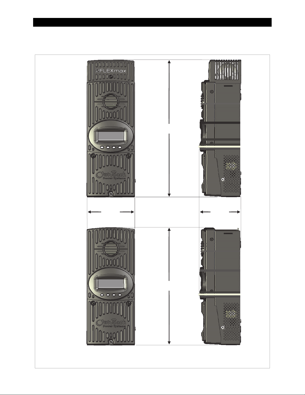
Dimensions
FLEXmax 80
Charge Controller
5.75”
(14.6 cm)
16.25” (41.3 cm)
4.0”
(10.2 cm)
FLEXmax 60
Charge Controller
13.5” (34.3 cm)
Figure 3 FLEXmax 80 and FLEXmax 60 Dimensions
8 900-0009-01-00 Rev C
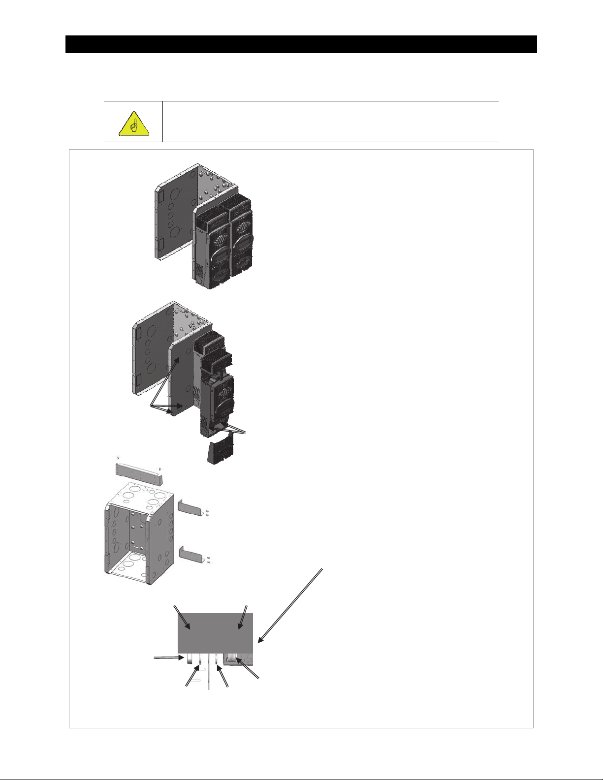
Mounting the Charge Controller
pp
IMPORTANT:
Install the FLEXmax in an upright position out of direct sunlight.
The FLEXmax is designed to attach
directly to OutBack’s FLEXware 500 DC
and FLEXware 1000 DC enclosures
(FLEXware 500 shown) or attach to its
own charge controller brackets (FW-CCB,
FW-CCB2, and FW-CCB2T).
Mounting directly to a FLEXware DC
enclosure:
1. Remove the fan cover and bottom
cover from the FLEXmax.
2. Insert a #10 X 3/8” sheet metal screw
in the top hole on the side of the DC
enclosure. This will act as a hanging
screw for the keyhole slot at the top
center of the FLEXmax.
Installation
Holes for
#10 x 3/8” sheet
metal screws
DC Enclosure
Bushing
3. Hang the FLEXmax on the top screw
Insert screws
through lower
holes inside
the charge
controller.
and line up its bottom two screw
holes with the holes on the enclosure.
4. Insert a #10 x 3/8” sheet metal screw
through each hole and tighten
against the enclosure (screws are
included with each DC enclosure).
5. Keep the cover off until wiring is
completed.
The conduit nipple assembly creates a
sealed connection from the FLEXmax to
the enclosure.
Charge Controller
(front view)
Mounting to Plywood
Use 1-5/8” wood screws to secure the
FLEXmax at the top slotted holes and
other interior lower holes as needed,
making sure the unit is straight and level.
Conduit
Lock Nut
Lock Nut
Ni
le
Figure 4 Mounting the Charge Controller
900-0009-01-00 Rev C 9
Installation
Wiring
This section provides instructions on installing PV array wiring into the FLEXmax controller. See
page 98 for more notes on PV array sizing and operation.
Wire and Disconnect Sizing
IMPORTANT:
Wire sizes must comply with local and national codes. Input conductors and circuit
breakers must be rated at 1.56 times the short-circuit current of the PV array (per
NEC). OutBack 100% duty continuous circuit breakers only need to be rated at 1.25
times the short-circuit current.
Copper wiring must be rated at 75°C or higher.
Use up to 2 AWG (33.6 mm
FLEXmax (smaller cables can reduce performance and possibly damage the unit).
FLEXmax 80
The output current limit of the FLEXmax 80 is 80 amps.
2
) to reduce losses and ensure high performance of the
Install OutBack PNL-80-DC circuit breakers for disconnect and overcurrent protection
Use a minimum of #4 AWG (25 mm
conductors.
The largest PV array must have a rated short-circuit current of 64 amps or less under STC (Standard
Test Conditions).
Torque all the FLEXmax wire lugs and ground terminals to 4 Nm (35 in-lb).
2
) wire for the output between the FLEXmax 80 and the battery bus bar
FLEXmax 60
The output current limit of the FLEXmax 60 is 60 amps.
Install OutBack PNL-60-AC/DC or PNL-80-DC circuit breakers for disconnect and overcurrent protection.
Use a minimum of #6 AWG (16 mm
conductors.
The largest PV array must have a rated short-circuit current of 48 amps or less under STC (Standard
Test Conditions).
Torque all the FLEXmax wire lugs and ground terminals to 4 Nm (35 in-lb).
Please refer to the NEC and other electrical codes for recommendations on PV array cable sizing and
recommended length and ampacity.
2
) wire for the output between the FLEXmax 60 and the battery bus bar
10 900-0009-01-00 Rev C
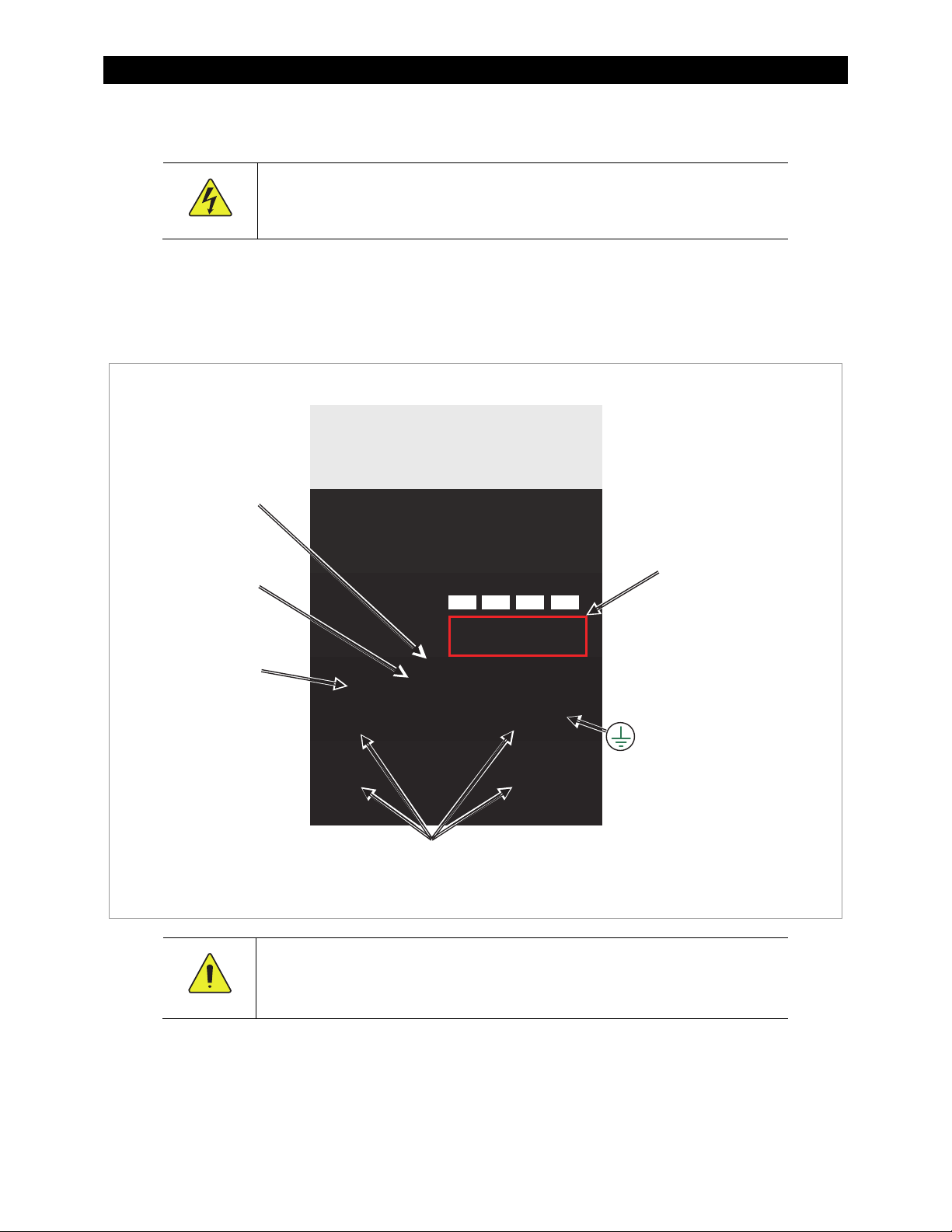
Installation
Wiring Compartment
WARNING: Shock Hazard
Make sure all DC circuit breakers are OFF (open) BEFORE making any wiring
connections. Use a DVM to check for voltage on all wires.
The PV (-) and BAT (-) terminals are connected internally. Only one negative wire may be needed to
connect to the (-) wire lugs if the PV - and BAT- conductors are bonded at the negative bus bar.
See Figure 6, Figure 7, and Figure 8 for sample wiring diagrams.
Auxiliary output
terminals
Battery Remote
Temp Sensor (RTS)
RJ11 port
MATE/HUB
RJ45 port
Wire terminals
PV+ PV– BAT– BA T+
Use up to 35 mm
(2 AWG) wire
Torque to 4 Nm
(35 in-lb)
Chassis/Equipment
Ground Lug
Screw holes for mounting the
charge controller
Figure 5 Wiring Compartment
CAUTION: Equipment Damage
Each FLEXmax requires its own PV array. DO NOT PARALLEL FLEXmax PV+ and PVTERMINALS ON THE SAME ARRAY!
2
An optional battery Remote Temperature Sensor (RTS) is recommended for accurate battery charging.
Only one RTS is needed for multiple OutBack inverter/chargers and charge controller units when the system
includes an OutBack HUB and a system display.
When one RTS is used, it must be connected to the component plugged into the Port 1 of the HUB.
900-0009-01-00 Rev C 11
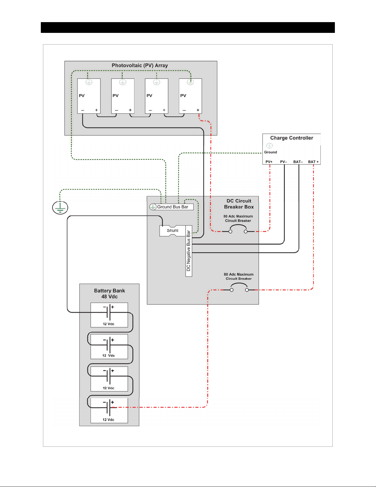
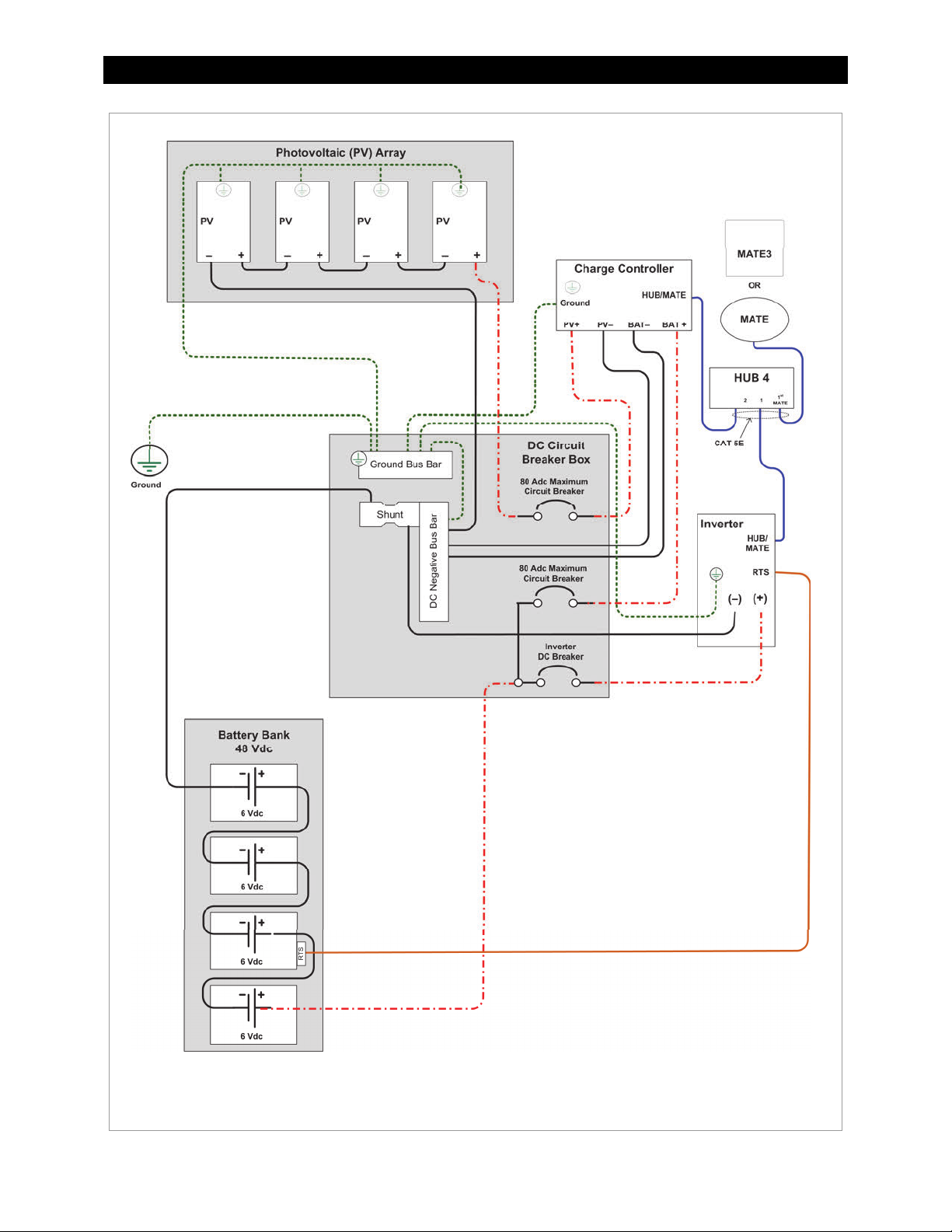
Installation
Figure 6 Wiring Diagram - Single Charge Controller with PV Array
12 900-0009-01-00 Rev C
Installation
Figure 7 Wiring Diagram – Charge Controller with PV Array and Inverter
900-0009-01-00 Rev C 13
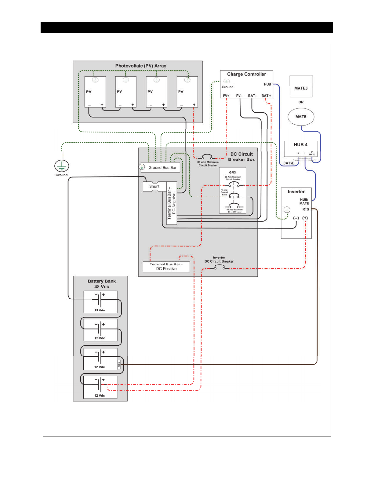
Installation
Figure 8 Wiring Diagram – Charge Controller with
PV Array Ground Fault Protection
14 900-0009-01-00 Rev C
Operation
T
Operation of this unit consists of monitoring screens and programming screens. The majority of
programming screens are accessed using the main menu. See page 24.
Power Up Screens
IMPORTANT:
The default settings of the FLEXmax are for a 12 Vdc battery bank. Change the
setting after powering up if a different battery voltage is used.
Once set, the FLEXmax retains the nominal voltage setting. Following any type of
shutdown or disconnect, it will return to operation automatically.
The PV array voltage is automatically detected. The PV array voltage must never
exceed 150 Voc.
It is recommended to restore the FLEXmax to factory default settings (see page 53)
and reset the nominal voltage any time the system is substantially revised or the
controller is relocated.
The FLEXmax uses power from the battery bank to operate. The battery voltage must be at least
10.5 volts or higher to power up the FLEXmax. When battery power is detected, the FLEXmax will go
through a series of power-up screens.
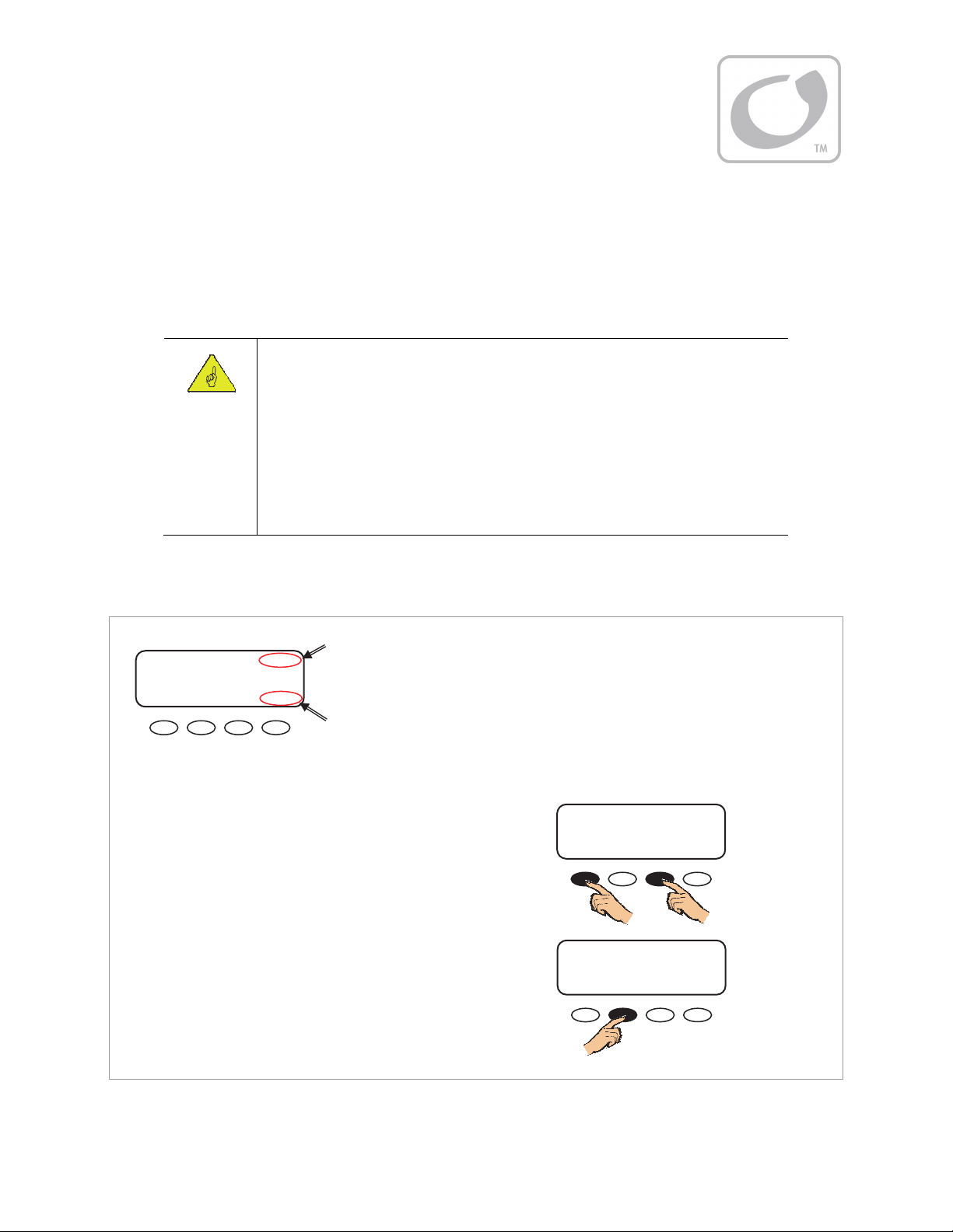
Power Up Screen
OutBack 12V
Power
Systems
Charge Controller - AU
To change version settings:
While turning on the circuit breaker, press and hold the first
and third soft keys. This brings up the Select Version screen.
Changing the version settings requires entering a password.
NOTE: This process will reset the FLEXmax to its default
settings. It may be necessary to re-enter previous settings.
To change the system password:
1. Press <NEXT> or <SEL> when the Select Version screen
appears on power up.
This will open the PASSWORD screen.
2. Press <–> or <+> to reduce the number from 150 to 141.
3. Press <ENTRA> or <ENTER> to enter the new password.
System Voltage
On Australian
versions only
To power up the charge controller:
1. Ensure the PV array and battery circuit breakers are OFF.
2. Turn ON the battery circuit breaker only.
upper right corner of the screen. If the screen reads
Low Battery Voltage, please see the Troubleshooting
section on page 91.
If the Australian version was previously selected, AU will
be displayed in the lower right corner of the screen.
Figure 9 Powering up the FLEXmax
he FLEXmax will show the system battery voltage in the
OutBack 12V
Power
Systems
Charge Controller - AU
PASSWORD
CONTRASENA
***150***
ENTRA - + ENTER
Continued on next page...
PASSWORD
Screen
Select Version offers two types of options. The English (default) or Spanish selections offer
standardized charge settings in two languages. Selecting Australian leaves the menus in English, but
changes the charging parameters. (For details, see Table 6 on page 99.)
900-0009-01-00 Rev C 15
Operation
Version and/or Voltage Setting Screens
Once the password has been entered, the display will return to the Select Version screen.
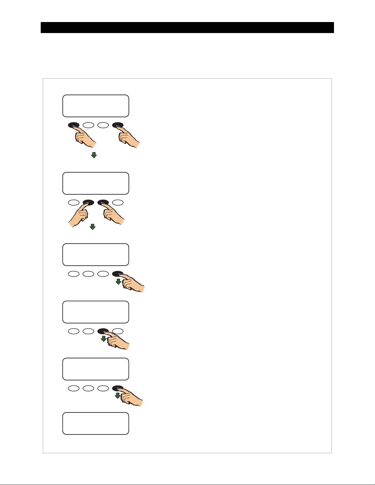
Select Version Screen
Select Version
Elija la Version
English
NEXT ENTER ENTRA SEL
or
Select Version Screen
Select Version
Elija la Version
English
NEXT ENTER ENTRA SEL
or
Confirmation Screen
Are you sure?
English
NO YES
SYSTEM VOLTAGE Screen
SYSTEM VOLTAGE
12 24 36 48 60
^^
ENTER
To change the version:
1. Press <NEXT> or <SEL> to cycle through the version
choices of:
English,
Australian, or
Espanola.
2. When the desired version is displayed, press <ENTER> or
<ENTRA> to proceed to the confirmation screen.
3. Press <YES> to confirm the selection.
The SYSTEM VOLTAGE screen appears next.
The FLEXmax automatically detects the system’s battery voltage
and indicates it by placing two ^^ symbols below the value.
Verification Screen
Are you sure?
12 24 36 48 60
^^
NO YES
If the value indicated is correct, press <ENTER>.
If the value indicate is not correct for the present system,
press <> to move the ^^ to below the correct voltage.
Press <YES> to confirm the selection.
Status Screen
In 11.6V 0.0 A
Out 13.8V 0.0 A
0.000 kW 0.0 kWH
AUX: OFF Sleeping
The Status screen is the last screen to be displayed after startup.
The soft keys below the Status screen navigate to the main
menu and the End-of-Day summary screen. See page 17 for
details on the Status screen.
Figure 10 Changing the Version Setting
16 900-0009-01-00 Rev C
Operation
Status Screen
The status screen displays system information. See page 18 for detailed information of the different
modes of operation.
The optional OutBack system display shows CC (Charge Controller) status screens for convenient
distant viewing from the installation location. See page 59 for the FLEXmax screens displayed on the
MATE3. Please see pages 71 to 83 to view the FLEXmax screens displayed on the MATE (or MATE2).
Status Screen
In 11.6V 0.0 A
Out 13.8V 0.0 A
0.000 kW 0.0 kWH
AUX: OFF Sleeping
In 11.6V 0.0 A
Out 13.8V 0.0 A
0.000 kW 0.0 kWH
AUX: OFF Sleeping
PV Input Voltage
PV Input Current
The PV voltage will slowly rise to the battery
voltage level even when the PV breaker is off –
this is normal as the PV capacitors charge up.
In 11.6V 0.0 A
Out 13.8V 0.0 A
0.000 kW 0.0 kWH
AUX: OFF Sleeping
In 11.6V 0.0 A
Out 13.8V 0.0 A
0.000 kW 0.0 kWH
AUX: OFF Sleeping
In 11.6V 0.0 A
Out 13.8V 0.0 A
0.000 kW 0.0 kWH
AUX: OFF Sleeping
In 11.6V 0.0 A
Out 13.8V 0.0 A
0.000 kW 0.0 kWH
AUX: OFF Sleeping
In 11.6V 0.0 A
Out 13.8V 0.0 A
0.000 kW 0.0 kWH
AUX: OFF Sleeping
Battery Voltage
Output Current
Instantaneous
Kilowatts
Daily Accumulated
Kilowatt-hours
AUX Status
(ON or OFF)
Navigation
Status Screen
In 11.6V 0.0 A
Out 13.8V 0.0 A
0.000 kW 0.0 kWH
AUX: OFF Sleeping
Pressing the first soft key (SK1)
opens the main menu screen.
Status Screen
In 11.6V 0.0 A
Out 13.8V 0.0 A
0.000 kW 0.0 kWH
AUX: OFF Sleeping
Pressing SK2 opens the end-of-day
summary menu and logging.
In 11.6V 0.0 A
Out 13.8V 0.0 A
0.000 kW 0.0 kWH
AUX: OFF Sleeping
Mode of Operation
See page 20
Figure 11 Status Screen
900-0009-01-00 Rev C 17
Operation
End-of-Day Summary Screen
The end-of-day summary screen appears after one hour of continuous Sleeping (see page 23). This
screen can be opened any time by pressing the second soft key while in the status screen, providing a
summary up to that point.
End-of-Day Screen
Today 000Ah 00.0kWH
011Vp 00.0Ap 0.00kWp
MAX 14.7 V ABS 01:00
MIN 14.6 V FLT 00:00
Day (up to 128 days)
Today 000Ah 00.0kWH
011Vp 00.0Ap 0.00kWp
MAX 14.7 V ABS 01:00
MIN 14.6 V FLT 00:00
Today 000Ah 00.0kWH
011Vp 00.0Ap 0.00kWp
MAX 14.7 V ABS 01:00
MIN 14.6 V FLT 00:00
Today 000Ah 00.0kWH
011Vp 00.0Ap 0.00kWp
MAX 14.7 V ABS 01:00
MIN 14.6 V FLT 00:00
Today 000Ah 00.0kWH
011Vp 00.0Ap 0.00kWp
MAX 14.7 V ABS 01:00
MIN 14.6 V FLT 00:00
Today 000Ah 00.0kWH
011Vp 00.0Ap 0.00kWp
MAX 14.7 V ABS 01:00
MIN 14.6 V FLT 00:00
Today 000Ah 00.0kWH
011Vp 00.0Ap 0.00kWp
MAX 14.7 V ABS 01:00
MIN 14.6 V FLT 00:00
Accumulated
Amp-hours
Accumulated kWh
Total Power
Peak Input Voltage
Peak Output Current
Peak Output Power
in Kilowatts
Maximum Battery
Voltage Obtained
NOTE:
When finished viewing the
end-of-day screen(s), be sure to
Today 000Ah 00.0kWH
011Vp 00.0Ap 0.00kWp
MAX 14.7 V ABS 01:00
MIN 14.6 V FLT 00:00
Today 000Ah 00.0kWH
011Vp 00.0Ap 0.00kWp
MAX 14.7 V ABS 01:00
MIN 14.6 V FLT 00:00
Accumulated
Absorb Time
Minimum Battery
Voltage Obtained
return the display to the status
screen. Otherwise, it will not reset
the counters when the sun rises the
next morning. The values will
continue to accumulate.
Today 000Ah 00.0kWH
011Vp 00.0Ap 0.00kWp
MAX 14.7 V ABS 01:00
MIN 14.6 V FLT 00:00
Accumulated
Float Time
Figure 12 End-of-Day Summary Screen
18 900-0009-01-00 Rev C
Operation
Navigating the End-of-Day Screens and Data Logging
Status Screen End-of-Day Screen
In 11.6V 0.0 A
Out 13.8V 0.0 A
0.000 kW 0.0 kWH
AUX: OFF Sleeping
Today 000Ah 00.0kWH
011Vp 00.0Ap 0.00kWp
MAX 14.7 V ABS 01:00
MIN 14.6 V FLT 00:00
Pressing the second soft key
(SK2) opens the end-of-day
summary menu/logging.
End-of-Day Screen
Today 000Ah 00.0kWH
011Vp 00.0Ap 0.00kWp
MAX 14.7 V ABS 01:00
MIN 14.6 V FLT 00:00
Press SK2 to open the
CLEAR LOG screen.
End-of-Day Screen
Today 000Ah 00.0kWH
011Vp 00.0Ap 0.00kWp
MAX 14.7 V ABS 01:00
MIN 14.6 V FLT 00:00
Press SK1 to return to the
status screen.
CLEAR LOG Screen
The daily statistics or the accumulated
statistics are stored on the charge controller's
static memory. A new log “day” begins when
the controller enters Wakeup. (See page 24.)
Logs accumulate for up to 128 days. See
pages 75 and page 76 for details.
CLEAR LOG
BACK TOTL DAILY
OR
Are you sure?
NO YES
OR
Press SK3 to open the previous
day’s summary screen.
Continuing to press this soft key
will cycle back through the last
128 daily summary screens.
End-of-Day Screen
Today 000Ah 00.0kWH
011Vp 00.0Ap 0.00kWp
MAX 14.7 V ABS 01:00
MIN 14.6 V FLT 00:00
End-of-Day Screen
Today 000Ah 00.0kWH
011Vp 00.0Ap 0.00kWp
MAX 14.7 V ABS 01:00
MIN 14.6 V FLT 00:00
Press SK1 to return to the
status screen.
This data log can be downloaded to an SD
Pressing SK4 will bring up
the summary for the 128
day back.
th
card. The MATE3 system display is required
for this download. See page 69 for details on
this feature.
Figure 13 Navigating the End-of-Day Summary Screen
900-0009-01-00 Rev C 19
Operation
Modes of Operation
The FLEXmax has 25 different modes that will display on the status screen. These messages will vary
with function. The FLEXmax modes consist of various charging stages, equalization, various reasons
for stopping charging, and certain specialized operating modes.
The amount of time required before starting operation is dependent on the module type, ambient
temperature, and the amount of sunlight directly on the PV array. Normally, the FLEXmax starts in the
morning within a few minutes of the PV array being exposed to direct sunlight.
The FLEXmax modes of operation will change occasionally during the day based on the PV array
output and the battery system state of charge. The FLEXmax operating modes are displayed at the
bottom right hand corner of the status screen. See Figure 11.
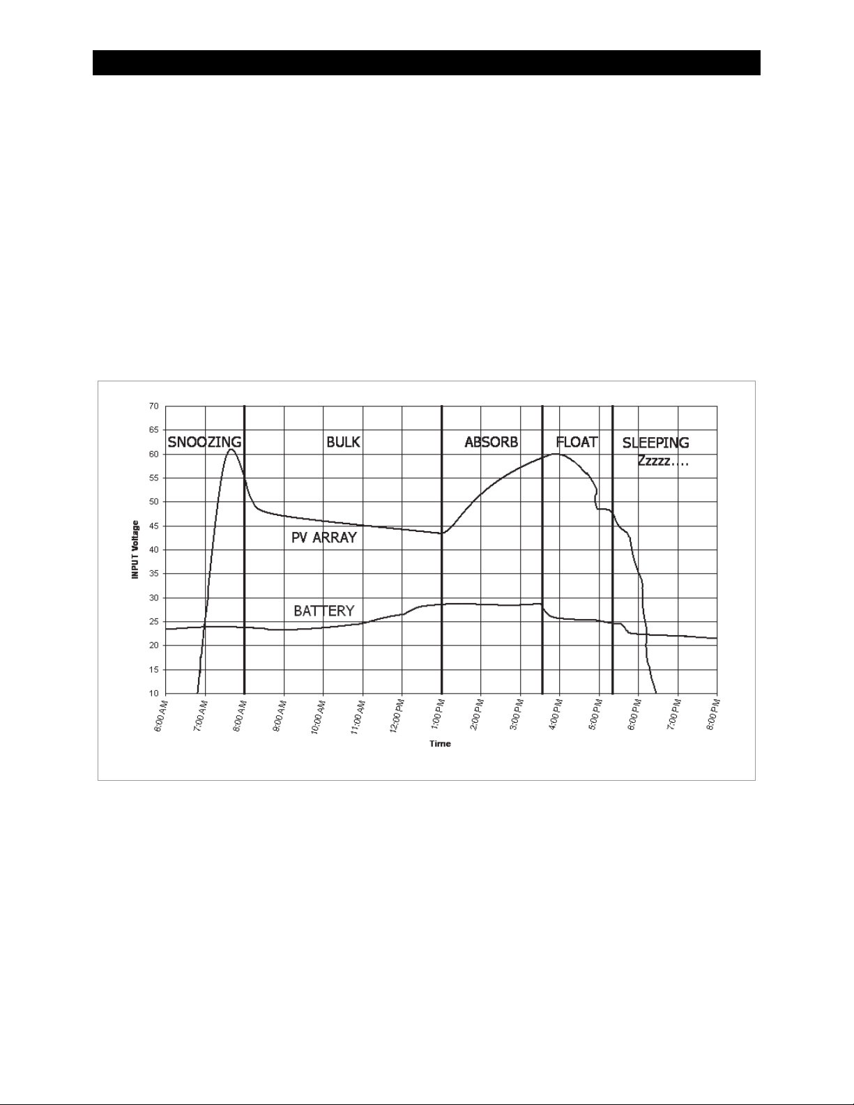
Figure 14 shows an example of the various stages of operation during battery charging and the
messages shown during each stage. Battery charging is described in detail on page 96.
Figure 14 FLEXmax Battery Charging and Modes
Absorbing
The FLEXmax is in the Absorbing stage of a three-stage cycle, regulating the battery voltage at the
Absorbing voltage set point. While the batteries are held at this voltage, the ChgT counter in the Misc
menu counts up from zero toward the user-defined Absorb Time Limit. (See pages 44 and 49.) The
charger will exit this stage and enter the Float stage if the ChgT timer reaches the time limit, or if the
Absorb End Amps setting is reached. (See page 49.)
If the battery voltage drops below the Absorbing voltage (see page 26), the FLEXmax reverts back to
the Bulk charge stage and displays MPPT Bulk as shown on page 22. The ChgT counter will begin
counting back toward zero. Lower voltages will cause the timer to subtract minutes at a faster rate, as
shown on Table 1 on page 21.
20 900-0009-01-00 Rev C

Operation
Table 1 Battery Voltage and Charge Timer
Battery Voltage ChgT (Charge Timer) Activity/Display
12.4 V, 24.8 V, 37.2 V, 49.6 V, or 62.0 V,
and less than the Absorbing voltage
<12.4 V, 24.8 V, 37.2 V, 49.6 V, or 62.0 V For every minute elapsed, 1 minute is
<12.0 V, 24.0 V, 36.0 V, 48.0 V, or 60.0 V For every minute elapsed, 2 minutes is
< 11.6 V, 23.2 V, 34.8 V, 46.6 V, or 58.0 V For every minute elapsed, 4 minutes is
No change.
subtracted from the timer
subtracted from the timer
subtracted from the timer.
Auto Start (Auto ReStart)
This setting allows the user to choose between continuous MPP tracking or occasional restarts of the
sweeping process. A restart means the controller abandons the existing maximum power point and
“re-sweeps”, or begins gathering new power point data. See page 52 for more information.
Mode 1: Once every 1.5 hours in the Bulk charging stage
Mode 2: Once every 1.5 hours in the Bulk, Absorbing and Float recharging stages
Mode 0: Auto ReStart is disabled completely. It will continously track the maximum power point without
starting over.
NOTE: If enabled, AutoStart also occurs during the MPPT EQ cycle. See page 23.
BatTmpErr
The battery temperature sensor is shorted or damaged. The charging voltage will not be temperature
compensated and the cooling fan will continuously operate. See the section on RTS compensation on
page 50.
BatTooHot
The battery temperature sensor has detected a battery temperature of over 50°C. The FLEXmax will
stop charging the battery and wait for the battery to cool below 50°C.
Charged
There is an external DC source other than PV keeping the battery above the Float voltage set point
(see page 26). The FLEXmax will stop charging because it is not needed. The display may also appear
when the cycle is transitioning from Absorbing (upper target voltage) to Floating (lower voltage).
EQ
The charger is in a cycle of equalization. (See page 42.) This is the time elapsed in hours and minutes
since the BATTERY EQUALIZE VOLTS set point was met.
If this set point is not maintained, the controller will revert back to MPPT EQ. (See page 23.) The EQ
timer will pause until the batteries are regulated at the BATTERY EQUALIZE VOLTS set point again.
The paused time can be viewed in the End-of-day Summary screen (see page 18).
EQ Done
Once the set EQ time (between 1 and 7 hours) has successfully completed, the FLEXmax will transition
to Float stage. EQ Done will be displayed either until a button is pressed or the next morning’s
wakeup. The FLEXmax will transition to Float stage at the end of the completed equalization cycle.
900-0009-01-00 Rev C 21
Operation
EX-Absorb
There is an external DC source other than PV keeping the battery above the Absorbing voltage set
point. The FLEXmax will stop charging because it is not needed.
Floating
The FLEXmax is in the Float stage of a three-stage cycle, regulating the battery voltage at the Float
voltage set point. This stage is temperature compensated. (See page 97.) If the battery voltage drops
below the Float voltage, the FLEXmax will employ the MPPT function to draw more power from the
PV array. (This may occur if the batteries are powering loads.) If this happens, the operating mode will
change to MPPT Float. (See below.)
GT Mode
The FLEXmax is in Grid-Tie mode. In a system with an OutBack grid-interactive inverter, a HUB, and a
system display, the FLEXmax will display GT Mode, if and only if, the inverter is in Sell mode and the
FLEXmax is in the MPPT BULK or MPPT FLOAT modes. This message also indicates that Grid-Tie mode
communication has been established between the inverter and charge controller. GT must be
selected in the MPPT Mode advanced menu in order to be viewed. (See page 47.)
High Voc
This indicates the PV array’s open-circuit voltage is too high for the controller to safely operate
(> 145 Vdc). This should only occur with systems using 72 Vdc nominal PV arrays in very cold
temperatures (below -15°C / 5°F). The FLEXmax will automatically restart operation once the PV
array’s open-circuit voltage falls to a safe level (145 Vdc or lower).
CAUTION: Equipment Damage
Voltages in excess of 150 Vdc are likely to damage the FLEXmax controller. The PV array
should be designed to avoid ever reaching these voltages.
Low Light or Snoozing
A Low Light or Snoozing mode indicates that the PV voltage is high enough to activate the FLEXmax,
but there is not enough current available to charge. During the initial tracking (see Wakeup and
Tracking), if it is determined to be too late (or too early) in the day, the FLEXmax will display Low Light
for a few seconds and then display Snoozing for five minutes (default). This reduces energy usage and
unnecessary powering of the FLEXmax. This message is also displayed in extremely cloudy weather.
MPPT Bulk
This is a Maximum Power Point Tracking mode which harvests the maximum wattage available from
the PV array. The controller is trying to regulate the battery voltage towards the Absorbing voltage
set point. Normally the charge controller enters this mode at the beginning of the day or when a new
charge cycle begins. The controller may also enter this stage if there is not enough PV energy to
maintain a different stage, such as Absorbing. See page 20 for more information.
MPPT Float
This is a Maximum Power Point Tracking mode which harvests the maximum wattage available from
the PV array. The controller is trying to regulate the battery voltage towards the Float voltage set
point. Normally, the charge controller enters this mode if it was in the Floating mode (see above) and
there was not enough energy to maintain the battery voltage.
22 900-0009-01-00 Rev C

Operation
MPPT EQ
The equalization cycle has started and the charge controller is trying to regulate the batteries at the
BATTERY EQUALIZE VOLTS set point. Once this voltage has been reached, the displayed mode will
change to EQ.
Before equalizing, battery loads should be turned off and the battery should be charged so the charge
controller can quickly reach the EQ voltage set point. Otherwise, the charge controller may have
difficulty reaching or maintaining the equalization process.
Equalization is not battery temperature compensated.
New Voc
The FLEXmax is measuring a new open-circuit panel voltage (Voc). This mode tells the user that
external conditions have changed. After displaying this message, the charge controller will enter
Tracking mode to perform power point tracking again.
OvrCurrent
This condition occurs if more than 6 amps flows from the battery to the FLEXmax, or if more than
100 amps is drawn from the FLEXmax by the battery. To reinitiate power production, press <RSTRT>
in the Misc menu (see page 45). If this continues to occur, the unit may be malfunctioning.
Over Temp
The FLEXmax is too hot. If this message appears, carefully check to see if the heat sink is extremely
hot. To help control its operating temperature, avoid installing the FLEXmax in direct sunlight.
Re-Cal
There are certain conditions that can confuse the current measuring method in the FLEXmax. If this
happens, the FLEXmax will temporarily stop and re-calibrate. This may happen because of high
temperatures or current flowing from the battery. After displaying this message, the charge controller
will enter Tracking mode to perform power point tracking again.
Sleeping
The PV voltage is two volts less than the battery voltage. This normally appears at night, when no PV
energy is available. This may also appear during the day when the FLEXmax is transitioning between
certain states, or due to other conditions. After three hours of Sleeping, the FLEXmax will transition to
Zzzzz... mode.
Sys Error
This indicates an internal non-volatile memory error. The unit will stop operating when this message
is displayed. Call OutBack Technical Support if this message appears (+1.360.618.4363).
Tracking
In Tracking mode, the FLEXmax is doing an initial tracking of the panel voltage from Voc towards
battery voltage after wakeup. This is also displayed when the controller transitions from a target set
point (Absorbing, Floating, or EQ) to the MPPT state (MPPT Bulk, MPPT Float, or MPPT EQ).
900-0009-01-00 Rev C 23
Operation
E
T
Unloaded
The battery terminals have become disconnected. This may mean that the battery circuit breaker
breaker has tripped. It can also appear if the nominal battery voltage is set too low.
Wakeup
As the PV open circuit voltage (Voc) rises above the battery system voltage by two volts, the FLEXmax
prepares to deliver power to the batteries, although it does not perform MPPT in this mode. During
this period (initial tracking), the FLEXmax is calculating the PWM duty cycles, turning on power supply
voltages in the proper sequences, and making internal calibrations. It also measures a new Voc at this
time. In Wakeup, the daily statistics of a single FLEXmax (amp-hours, kilowatt-hours, etc.), will
accumulate into the total statistics. The daily statistics and the end-of-day summary will clear, and the
controller will begin logging a new “day”. A FLEXmax combined with a HUB and a MATE will log this
information at midnight. On the MATE3, the data logging will occur at the interval scheduled in the
MATE3 data logging parameters.
Zzzzz...
The FLEXmax will display Zzzzz... after 3 hours of continuous Sleeping. This transition indicates that
the controller recognizes it is night. It will perform Wakeup when voltage is available (see above).
Initial Operation
Status
Screen
In 113.6V 0.0 A
Out 12.5V 0.0 A
0.000 kW 0.0 kWH
AUX: OFF Sleeping
Status
Scr
een
In 000.0V 0.0 A
Out 12.5V 0.0 A
0.000 kW 0.0 kWH
AUX: OFF Sleeping
urn the PV input circuit breaker ON. The FLEXmax automatically detects the
PV input voltage.
The FLEXmax enters Wakeup, transitions to Tracking, and prepares to
charge the batteries by tracking the maximum power point of the solar array.
During the initial tracking, the input PV source is gradually loaded from the
open-circuit voltage (Voc) to ½ of the Voc. Within this range, the FLEXmax
seeks the maximum power point.
When the FLEXmax goes into Re-Cal, Auto Restart, or Wakeup, modes,
among other conditions, it performs an initial tracking.
If PV voltage registers 000V when the PV circuit breaker is
ON, check the polarity of the PV connections.
Figure 15 Initial Operation
Changing the Settings on the FLEXmax
Accessing the Main Menu
The main menu allows the user to adjust and calibrate the FLEXmax for maximum performance.
Status Screen
From the status screen, press SK1 to
open the main menu screen.
To return to the status screen from the
main menu, press <EXIT>
(also SK1).
In 113.6V 0.0 A
Out 12.5V 0.0 A
0.000 kW 0.0 kWH
AUX: OFF Sleeping
Figure 16 Accessing the Main Menu
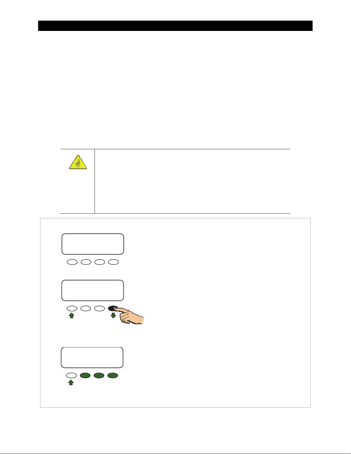
Main Menu
Charger Aux Light
EQ Misc Advanced
Logging Stats
XIT GO
24 900-0009-01-00 Rev C

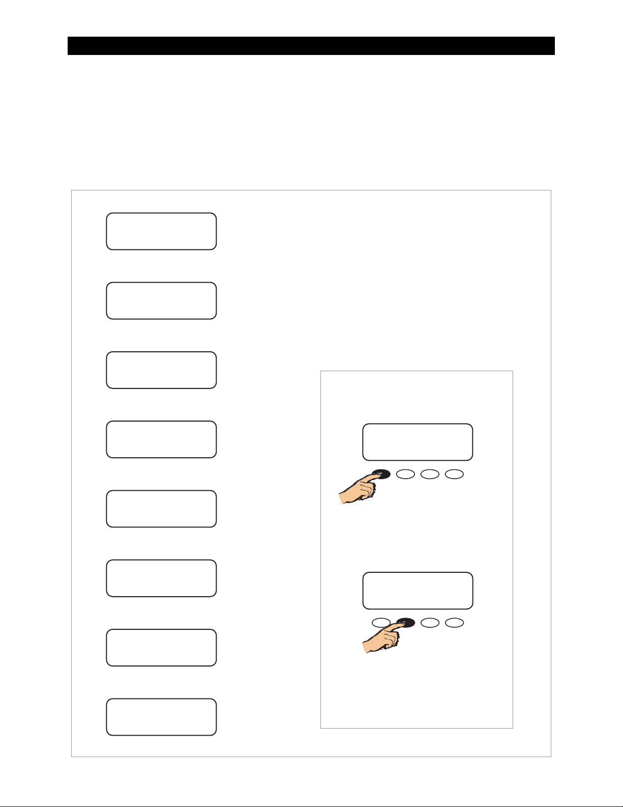
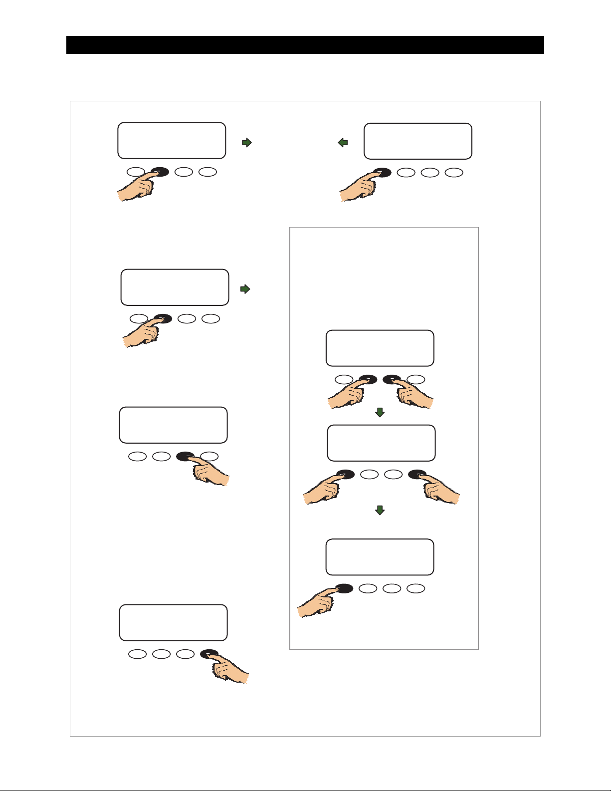
Main Menu Map
Operation
Main Menu
Charger Aux Light
EQ Misc Advanced
Logging Stats
EXIT GO
<EXIT> returns to the Status screen.
<> moves the cursor to the left.
<> moves the cursor to the right.
<GO> goes to the setup screen for the
chosen option.
Charger Aux Light
EQ Misc Advanced
Logging Stats
EXIT GO
Charger Aux Light
EQ Misc Advanced
Logging Stats
EXIT GO
Charger Aux Light
EQ Misc Advanced
Logging Stats
EXIT GO
Charger Aux Light
EQ Misc Advanced
Logging Stats
EXIT GO
Charger Aux Light
EQ Misc Advanced
Logging Stats
EXIT GO
Charger Aux Light
EQ Misc Advanced
Logging Stats
EXIT GO
Charger Aux Light
EQ Misc Advanced
Logging Stats
EXIT GO
Charger Aux Light
EQ Misc Advanced
Logging Stats
EXIT GO
Figure 17 Main Menu
From the main menu, a user can choose among the
following FLEXmax functions by aligning the arrow
next to the desired selection.
Charger—CHARGER SETUP
Adjusts the Current Limit, Absorbing,
and Float recharging voltage set points.
See page 26 for details.
Aux
Provides a secondary control circuit for a vent fan,
See page 27 for details.
Light—BACKLIGHT CONTROL
Adjusts the backlighting of LCD screen and soft
See page 41 for details.
Activates battery equalization recharging
See page 42 for details.
Additional settings and service information.
See page 44 for details.
Optimizes/fine-tunes the charge controller.
See page 46 for details.
Logging—DATA LOGGING
Displays recorded power production information.
See page 54 for details.
Displays recorded peak system information and
See page 55 for details.
—AUX OUTPUT CONTROL
error alarm, and other system-related additions.
key buttons.
EQ
—BATTERY EQUALIZE
(manually or automatically).
Misc
—MISCELLANEOUS
Advanced
STATS
cumulative kilowatt-hours and amp-hours.
—ADVANCED MENU
—STATISTICS
900-0009-01-00 Rev C 25
Operation
Charger Screen
Charging settings should follow the battery manufacturer's recommendations. This screen allows
changes to the recharging voltage set points if the default settings do not match the manufacturer's
recommendations. (For an explanation of battery charging, see pages 96 and 97).
Current Limit
Absorbing
Float
The default charger output current limit setting is:
80 amps for the FM80, and
60 amps for the FM60.
This setting is adjustable from 5-80 amps.
IMPORTANT:
Check the battery manufacturer’s recommendations for the optimal charging
settings for the type of batteries being used.
An appropriate circuit breaker, or overcurrent device, must be used between the
battery and the FLEXmax.
If a battery remote temperature sensor (RTS) is used, set the Absorbing and Float
setting voltage based on a 25°C/77°F setting. RTS compensated voltage values can
be viewed in the Advanced menu screen under the RTS Compensation heading.
Main Menu
Charger Aux Light
EQ Misc Advanced
Logging Stats
EXIT GO
Charger Aux Light
EQ Misc Advanced
Logging Stats
EXIT GO
To access the Charger screen and adjust the settings:
1. From the main menu, press the <> or <> soft key to
move the
2. Press <GO> to open the Charger screen.
The indicates which set point is selected.
3. Press <> to move the to the set point that needs to
be changed.
4. Press <+> to increase the value or (–) to decrease
the value.
to the left of the Charger function.
Charger Screen
Current Limit 80A
Absorbing 14.4V
Float 13.8V
EXIT
- +
To Exit:
Press <EXIT> once to return to the main menu.
Press <EXIT> twice to return to the status screen.
Figure 18 Charger Setup Menu
26 900-0009-01-00 Rev C

Operation
Aux Screens
The AUX (Auxiliary) is a secondary control circuit — essentially, a small power supply that provides a
12 Vdc output current (up to 200 milliamps/2.4 watts) to an isolated load. It is either ON (Active High)
with 12 Vdc available at the output or OFF (Active Low) with 0 Vdc at the output. It can also be set to
AUTO, so that it activates when certain criteria are met.
The AUX output can respond to specific criteria and control cooling fans, vent fans, load diversion,
fault alarms, and automatic generator control. In some cases, such as the PV Trigger, Night Light, or
Diversion:Relay applications, the polarity of the output can be reversed so that a lack of power
activates the output. This function is controlled through the Aux Polarity screen in the ADVANCED
MENU. (See page 53.)
NOTE: Diversion:Relay and Diversion:Solid St can be used for AC coupling applications.
The AUX output can also be controlled externally through the system display. See the Owner's Manual
for the system display (if used) for details.
Only one
See Figure 27, page 39, for an auxiliary setup wiring diagram example.
AUX MODE
Mode Name Function/Purpose Set Points Aux Polarity
Vent Fan
Function:
When the threshold voltage set point is
exceeded, the AUX output will change state for
at least 15 seconds. If the set point continues to
be exceeded, the output will remain in that state
until the voltage falls below the set point.
Once the voltage decreases below the threshold
voltage, the AUX output will remain in that state
for another 15 seconds. It will then deactivate.
Purpose:
This mode is intended to operate a vent fan for a
battery enclosure to ventilate hydrogen gas
from the enclosure.
can operate at a time (even if other modes have been preset).
Table 2 Aux Mode Functions
Threshold
Voltage
Not Available
PV Trigger
900-0009-01-00 Rev C 27
Function:
When the threshold voltage set point is
exceeded, the AUX output will activate.
When the threshold voltage decreases below
the voltage set point, the output will remain
active for the duration of the hold time set by
the user.
Purpose:
This mode is intended to operate an alarm, or
relay that disconnects the PV array, when
PV input exceeds the threshold voltage set by
the user. The mode deactivates the alarm or
PV disconnect after the time set point has
reached.
been
NOTE: Do not exceed 150 Vdc or the FLEXmax
could be damaged.
Threshold
Voltage
Hold Time
Active High: Activates the
output when the voltage
exceeds the set point.
Active Low: Deactivates the
output when the voltage
exceeds the set point.

Operation
Table 2 Aux Mode Functions
Mode Name Function/Purpose Set Points Aux Polarity
Error Output
Night Light
Float
Diversion:
Relay
Function:
When the voltage decreases below the
threshold voltage for 10 minutes or more, the
AUX output will change state.
Purpose:
This mode is useful for monitoring remote sites.
It is intended to signal when the charge
controller has not charged the batteries for 26
hours or more or if the battery voltage has fallen
below the threshold voltage for more than 10
minutes.
When set as Active Low, it can activate an alarm
by sending a signal through a modem to a
computer to alert the operator of the problem.
Function:
When the voltage drops below the threshold
voltage set point for the amount of time set in
the Hysteresis time, the AUX output changes
states and remains in that state for the amount
of time set for the ON time.
Purpose:
This mode is intended to illuminate a
user-provided, low wattage light for as long as
the charge controller remains in Sleep mode or
for the ON time set by the user.
Function:
When the FLEXmax is in the Float stage, the
output activates to power a load.
Purpose:
This mode is intended to power a load when the
FLEXmax is in the Float stage of charging the
batteries.
Function:
When the battery voltage exceeds the threshold
voltage, the AUX output changes state. Often
used with wind or hydroelectric sources.
Purpose:
This mode is intended to divert power from the
batteries to prevent overcharging by activating
a diversion load at the appropriate time.
Threshold
Voltage
Threshold
voltage
ON Time
Hysteresis
Time
None Not Available
Threshold
Voltage
Time
Not Available
Active High: Activates for a
set amount of time when the
voltage drops below the
threshold for a set amount
of time.
Active Low: Deactivates for a
set amount of time when the
voltage drops below the
threshold for a set amount of
time.
Active High: Controls an
auxiliary load to divert power
away from the batteries when
a wind or hydroelectric turbine
is connected directly to the
batteries.
Active Low: Deactivates an
auxiliary load to stop diverting
from batteries.
Diversion: Solid
St
Function:
When the battery voltage exceeds the threshold
voltage, the AUX output goes into pulse-width
modulation at a rate of 200 Hz. Often used with
wind or hydroelectric sources.
Purpose:
This mode is intended to divert power from the
batteries to prevent overcharging by operating
a diversion load at the appropriate PWM level.
Recommended for use with a solid-state relay
for fast and precise load control.
Threshold
Voltage
Time
Not Available
28 900-0009-01-00 Rev C
 Loading...