


 netTM DC
User’s Guide
Includes Mounting and Installation
Warranty
Dear OutBack Customer,
Thank you for your purchase of OutBack products. We make every effort to assure our power conversion products will give you long and reliable service for your renewable energy system.
As with any manufactured device, repairs might be needed due to damage, inappropriate use, or unintentional defect. Please note the following guidelines regarding warranty service of OutBack products:
•Any and all warranty repairs must conform to the terms of the warranty.
•All OutBack equipment must be installed according to their accompanying instructions and manuals with specified over-current protection in order to maintain their warranties.
•The customer must return the component(s) to OutBack, securely packaged, properly addressed, and shipping paid. We recommend insuring your package when shipping. Packages that are not securely packaged can sustain additional damage not covered by the warranty or can void warranty repairs.
•There is no allowance or reimbursement for an installer’s or user’s labor or travel time required to disconnect, service, or reinstall the damaged component(s).
•OutBack will ship the repaired or replacement component(s) prepaid to addresses in the continental United States, where applicable. Shipments outside the U.S. will be sent freight collect.
•In the event of a product malfunction, OutBack cannot bear any responsibility for consequential losses, expenses, or damage to other components.
•Please read the full warranty at the end of this manual for more information.
About OutBack Power Systems
OutBack Power Systems is a leader in advanced energy conversion technology. Our products include true sine wave inverter/chargers, maximum power point tracking charge controllers, system
communication components, as well as breaker panels, breakers, accessories, and assembled systems.
Notice of Copyright
FLEXnet DC User’s Guide © 2007 All rights reserved.
1
Disclaimer
UNLESS SPECIFICALLY AGREED TO IN WRITING, OUTBACK POWER SYSTEMS:
(a)MAKES NO WARRANTY AS TO THE ACCURACY, SUFFICIENCY OR SUITABILITY OF ANY TECHNICAL OR OTHER INFORMATION PROVIDED IN ITS MANUALS OR OTHER DOCUMENTATION.
(b)ASSUMES NO RESPONSIBILITY OR LIABILITY FOR LOSS OR DAMAGE, WHETHER DIRECT, INDIRECT, CONSEQUENTIAL OR INCIDENTAL, WHICH MIGHT ARISE OUT OF THE USE OF SUCH INFORMATION. THE
USE OF ANY SUCH INFORMATION WILL BE ENTIRELY AT THE USER’S RISK.
Date and Revision
January, 2008
Contact Information
OutBack Power Systems 19009 62nd Ave. NE Arlington, WA 98223 Phone (360)435-6030 Fax (360)435-6019 outbackpower.com
2
TABLE OF CONTENTS
Warranty Summary..................................................................................................................................................................... |
1 |
Introduction.................................................................................................................................................................................... |
4 |
System Overview......................................................................................................................................................................... |
5 |
Reading the FLEXnet DC......................................................................................................................................................... |
6 |
FLEXnet DC Package ................................................................................................................................................................. |
7 |
Installing the FLEXnet DC................................................................................................................................................ |
7-10 |
FLEXnet DC Measurements ................................................................................................................................................ |
11 |
Logged Data................................................................................................................................................................................. |
12 |
User Adjustable Set Points................................................................................................................................................... |
12 |
Programming and Using the MATE for FLEXnet Operations.......................................................................... |
13 |
FLEXnet DC Modes................................................................................................................................................................... |
14 |
Programming the Auxiliary Relay.................................................................................................................................... |
16 |
MATE Screens....................................................................................................................................................................... |
17-28 |
Technical Notes........................................................................................................................................................................... |
29 |
Warranty.................................................................................................................................................................................. |
30-31 |
Warrranty Registration............................................................................................................................................................ |
32 |
3
Introduction
The OutBack Power Systems FLEXnet DC
The FLEXNet DC collects, monitors and records time-based battery amp, watt and volt data for display on the OutBack MATE series of products, allowing for more accurate set point adjustments and precise battery recharging. Five LEDs on the FLEXnet DC act as a state-of-charge indicator bar for a quick status display.
The FLEXnet DC also offers an auxiliary (AUX) relay that acts like a switch to turn on or off a user-installed light, alarm, or similar low voltage DC device. It can also be set up as a two-wire auto generator starter.
The FLEXNet DC works in conjunction with up to three input current shunts (either a FW-SHUNT250 or FW-SHUNT500, each rated 500A/50mV) also available from OutBack.
Only a single FLEXNet DC is needed for any system using OutBack components.
The FLEXnet DC is not intended to be used with the MATE2M. It is designed to work with the MATE or the MATE2.
NOTE: • One shunt is included as standard equipment with each OutBack FW500-DC and FW1000-AC enclosures.
• The shunt(s) cannot be connected to a positive (+) ground system.
4

SYSTEM OVERVIEW
BAT + |
BAT - |
C BAT (-)
C DEVICE
B DEVICE


 netTM DC
CHARGE CONTROLLER BATTERY -
SHUNT C
CHARGE CONTROLLER
FX BATTERY -
SHUNT B
B BAT (-)
|
)-( BAT A |
DEVICE A |
|
||
|
|
FX INVERTER/CHARGER |
|
|
|
|
|
|
|
BATTERY - |
OTHER DC |
|
|
SOURCE OR |
|
|
|
SHUNT A |
LOAD |
|
|
||
Think of the input shunts as breaks or junctions in the DC (-) conductor. The current is conducted as though it were a continuous conductor, but the shunts allow the user to monitor the current, providing information for more accurate battery recharging.
5
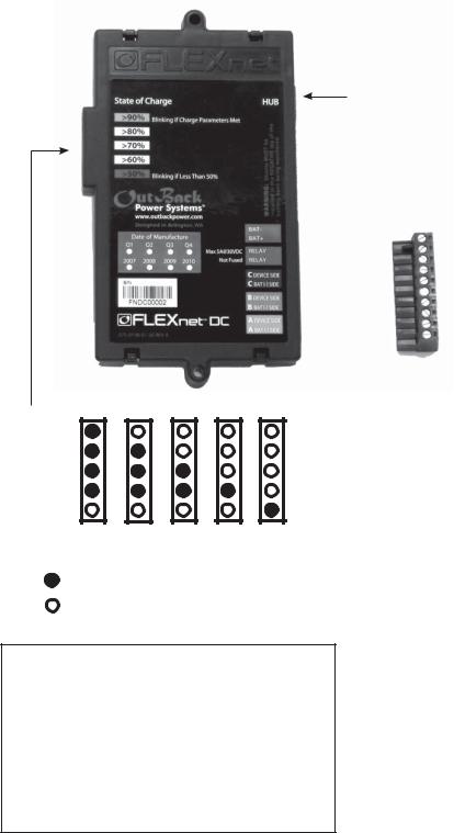
Reading the FLEXnet DC
RJ45 jack connects to
Port 2 or higher in HUB
LEDs* 
1
2
3
4
5
6
7
8
9
10
(GREEN)
(YELLOW)
(YELLOW)
(YELLOW)
(RED)
SOC >90% 80-89% 70-79% 60-69% 50-59%
ON
OFF
•Blinking green LED: Charge parameters met
•Solid green LED: SOC** is above 90%
•Solid red LED: SOC is greater than 49% but less than 60%
•Off red LED: SOC is above 59%
•Blinking red LED: SOC is less than 50%
*See page 15 **State of Charge
10-postion wiring block
1:BAT-
2:BAT+ 3. Relay 4. Relay
5:C DEVICE SIDE
6:C BAT (-) SIDE
7:B DEVICE SIDE
8:B BAT (-) SIDE
9:A DEVICE SIDE
10:A BAT (-) SIDE
•BAT+/- must connect directly to battery terminals of the bank being monitored.
•Proper polarity must be observed on all connections.
6
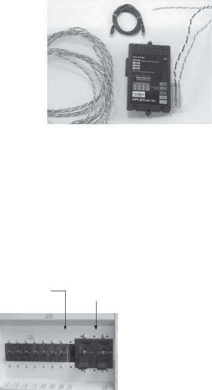
The FLEXNet DC package includes:
A. FLEXnet DC
B. Ten-pin wiring plug for shunt, relay |
C |
D |
||
|
||||
|
and battery connections |
|
||
|
|
|
||
C. Six feet of CAT5 cable for HUB connection |
E |
|
||
D. Ten-foot color-coded twisted pair |
E |
|||
A |
||||
|
(TP) cable connects to the battery |
|
|
|
E. |
Three six-foot, color-coded, |
|
|
|
|
twisted pair cables for shunt connections |
|
|
|
F. |
Two #6-32 X 3/8” panhead |
|
B |
|
|
machine screws |
|
||
|
|
|
||
G. Colored labels identifying shunts
Installing the FLEXnet DC
The FLEXnet DC mounts in a 3/4” DC breaker slot in an OutBack DC breaker bracket installed inside a FLEXware enclosure or previous model OutBack enclosure. To mount the FLEXnet DC inside an OutBack enclosure:
1.Put the system into bypass mode
2.Shut off all AC input to inverters
3.Shut off all PV and DC breakers
4.Disconnect the battery cables at the battery
5.Remove the breaker bracket from its enclosure by removing the four corner screws
6.Remove a DC breaker knockout
FLEXnet DC mounts in a DC breaker
slot after removing the breaker DC breakers off knockout
PV breakers off
7
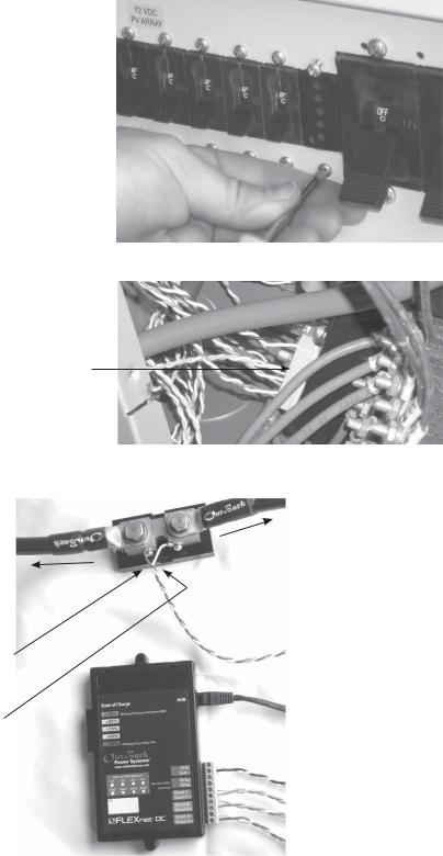
•Insert the FLEXNet DC inside the DC breaker box and through the back side of the breaker bracket; secure with two #6-32 X 3/8 panhead machine screws (included) torqued at 5 to 8 inch-pounds
•Connect all wires to the ten-pin wiring connector. Do not leave any loose wires!
•Connect each twisted pair to a shunt.
Source/Load Negative
Battery Negative
Example:
•Battery side (green wire in twisted pair) connects to the battery negative side of the shunt
•Device side (white wire in twisted pair) connects to the source/load (negative) side of the shunt
NOTE: Color of wiring jacket can vary
NOTE: The FLEXNet DC shunts must be connected in the negative (low) side of whatever they monitor. Otherwise, the unit can be damaged.
8
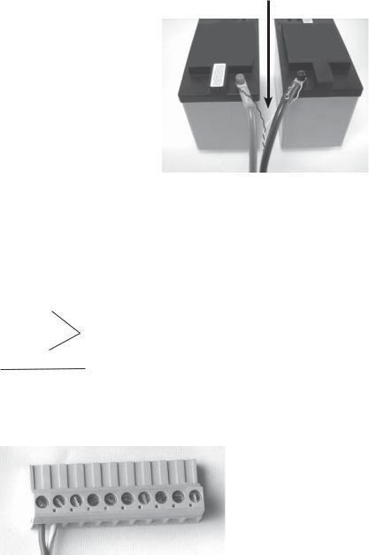
• Black/White twisted pair connects directly to the battery bank being monitored:
BLACK/WHITE TWISTED PAIR
 White to BAT (-)
 Black to BAT (+)
 An appropriate fuse—with a rating of 5 amps or less and greater than 100 volts
DC—may be placed in the black conductor
Wiring Block Connections
Color-coded twisted pair 18 AWG connects the wiring block and shunt(s) or battery. The wiring must be installed with the proper polarity to avoid corrupting the data.
The wires connected to the wiring block should match the color-coded label where the wiring block inserts into the FLEXnet DC.
•Green and White/Green
•Orange and White/Orange
•Blue and White/Blue
•Black and White
6’ twisted pair wires with #8 forked spade terminals connected to the shunts
10’ twisted pair wire with 5/16” ring terminals connected to the battery bank
The wiring block can accommodate #12 AWG to #26 AWG (2.5 mm2 to .20 mm2) wire with a strip length of 1/4” (6 mm).
Torque Values
•Five inch-pound maximum torque on each terminal block screw
•4-5 inch-pound torque is recommended if using the supplied 18 AWG stranded twisted pair wire
9
(Installing the FLEXnet DC continued)
•Insert the 10-pin connector to the wiring block on the back of the FLEXnet DC.
•Install the CAT5 cable into the RJ45 jack in the back
of the FLEXNet DC. Connect the other end of the
cable to the HUB using Port #2 or higher.
FLEXnet DC removed from the breaker bracket for clarity.
•Replace the breaker bracket and secure with its four corner fasteners.
•With all FLEXnet DC wires connected, reinstall the DC enclosure cover and secure its four Phillips screws.
•After the cover is installed, reconnect the battery cables at the battery, turn on all the breakers, and power up the system.
10
 Loading...