


FS-91S
It is of vital importance, before attempting to
operate your engine, to read the general
'SAFETY INSTRUCTIONS AND WARNINGS'
section on pages 2-4 of this booklet and to
strictly adhere to the advice contained therein.
Also, please study the entire contents of this
•
instruction manual, so as to familiarize
yourself with the controls and other features
of the engine.
Keep these instructions in a safe place so that
•
you may readily refer to them whenever
necessary.
It is suggested that any instructions supplied
•
with the aircraft, radio control equipment, etc.,
are accessible for checking at the same time.

CONTENTS
SAFETY INSTRUCTIONS AND
WARNINGS ABOUT YOUR O.S. ENGINE
INTRODUCTION, INSTALLING THE GLOWPLUG
RELOCATION OF CARBURETTOR CONTROLS
FUEL TANK, INSTALLATION
EXHAUST HEADER PIPE AND SILENCER,
THROTTLE LINKAGE,
NEEDLE-VALVE EXTENSION
FUEL LINES
CARE OF FUEL PUMP AND REGULATOR,
PROPELLERS
GLOWPLUGS, FUEL
PROPELLER AND SPINNER ATTACHMENT,
TYPE 60R, 60P AND 60N CARBURETTOR
2-4
5
6
7
8
8-9
9-10
11-12
12
STARTING
RUNNING-IN
IDLING MIXTURE ADJUSTMENT
VALVE ADJUSTING
CARE AND MAINTENANCE
O.S. GENUINE PARTS & ACCESSORIES
ENGINE EXPLODED VIEWS &
ENGINE PARTS LISTS
CARBURETTOR EXPLODED VIEWS &
PARTS LIST
ENGINE THREE VIEW DRAWINGS
13
13-14
15
15-17
17-18
19
20-25
26-27
28-30
1
SAFETY INSTRUCTIONS AND
WARNINGS ABOUT YOUR
O.S. ENGINE
Remember that your engine is not a " toy ", but a highly
efficient internal-combustion machine whose power is
capable of harming you, or others, if it is misused or
abused. As owner, you, alone, are responsible for the safe
operation of your engine, so act with discretion and care at
all times.
If at some future date, your O.S. engine is acquired by
another person, we would respectfully request that these
instructions are also passed on to its new owner.
The advice which follows is grouped under two headings
■
according to the degree of damage or danger which
might arise through misuse or neglect.
WARNINGS
These cover events which might involve serious (in
extreme circumstances, even fatal ) injury.
NOTES
These cover the many other possibilities, generally less
obvious sources of danger, but which, under certain
circumstances, may also cause damage or injury.
WARNINGS
Never touch, or allow any object to come into
•
contact with, the rotating propeller and do not
crouch over the engine when it is running.
A weakened or loose propeller may disintegrate or be thrown
•
off and, since propeller tip speeds with powerful engines may
exceed 600 feet(180 metres) per second, it will be understood
that such a failure could result in serious injury, (see 'NOTES'
section relating to propeller safety).
Model engine fuel is poisonous. Do not allow it to
•
come into contact with the eyes or mouth. Always
store it in a clearly marked container and out of
the reach of children.
Model engine fuel is also highly flammable. Keep it
•
away from an open flame, excessive heat, sources
of sparks, or anything else which might ignite it.
Do not smoke or allow anyone else to smoke, near
to it.
Never operate your engine in an enclosed space. Model
•
engines, like automobile engines, exhaust deadly carbonmonoxide. Run your engine only in an open area.
Model engines generate considerable heat. Do
•
not touch any part of your engine until it has
cooled. Contact with the muffler(silencer),
cylinder head or exhaust header pipe, in
particular, may result in a serious burn.
2

NOTES
This engine was designed for model aircraft. Do not attempt to use it for any other purpose.
•
Mount the engine in your model securely, following the manufacturers' recommendations, using appropriate
•
screws and locknuts.
Be sure to use the silencer (muffler) supplied with the engine. Frequent exposure to an open exhaust may
•
eventually impair your hearing.
Such noise is also likely to cause annoyance to others over a wide area.
Fit a top-quality propeller of the diameter and pitch specified for the engine and aircraft. Locate the propeller on the
•
shaft so that the curved face of the blades faces forward-i.e. in the direction of flight. Firmly tighten the propeller nut,
using the correct size wrench.
Always check the tightness of the propeller nut and retighten it, if necessary, before restarting the engine,
•
particularly in the case of four-stroke-cycle engines. A safety locknut assembly is provided. Always use it. This will
prevent the propeller from flying off in the event of a "backfire", even if it loosens.
If you fit a spinner, make sure that it is a precision made product and that the slots for the propeller blades do not
•
cut into the blade roots and weaken them.
Discard any propeller which has become split, cracked, nicked or otherwise rendered unsafe. Never attempt to
•
repair such a propeller: destroy it. Do not modify a propeller in any way, unless you are highly experienced in tuning
propellers for specialized competition work such as pylon-racing.
Use an electric starter for this engine. The wearing of safety glasses is also strongly recommended.
•
3

NOTES
Take care that the glow plug clip or battery leads do not come into contact with the propeller.
•
Also check the linkage to the throttle arm. A disconnected linkage could also foul the propeller.
After starting the engine, carry out any needle-valve readjustments from a safe position behind the rotating
•
propeller. Stop the engine before attempting to make other adjustments to the carburettor.
Adjust the throttle linkage so that the engine stops when the throttle stick and trim lever on the transmitter are fully
•
retarded. Alternatively, the engine may be stopped by cutting off the fuel supply. Never try to stop the engine
physically.
Take care that loose clothing (ties, shirt sleeves, scarves, etc.) do not come into contact with the propeller.
•
Do not carry loose objects (such as pencils, screwdrivers, etc.) in a shirt pocket from where they could fall through
the propeller arc.
Do not start your engine in an area containing loose gravel or sand. The propeller may throw such material in your
•
face and eyes and cause injury.
For their safety, keep all onlookers (especially small children) well back (at least 20 feet or 6 meters) when preparing
•
your model for flight. If you have to carry the model to the take-off point with the engine running, be especially
cautious. Keep the propeller pointed away from you and walk well clear of spectators.
Warning! Immediately after a glowplug-ignition engine has been run and is still warm, conditions sometimes exist
•
whereby it is just possible for the engine to abruptly restart if the propeller is casually flipped over compression
WITHOUT the glowplug battery being reconnected. Remember this if you wish to avoid the risk of a painfully rapped
knuckle!
4
INTRODUCTION
The O.S. FS-70S2, FS-91S2 and FS-91S2-P are built, like
all O.S. engines, to the highest engineering standards, by a
company that was established in 1936 to manufacture 2-stroke
engines and which pioneered the production of four-strokecycle model aircraft engines 40 years later.
The FS-91S
type fuel pump and matching Type 60N carburettor
incorporating a built-in pressure regulator. These features
ensure that fuel/air mixture strength is maintained at a constant
level through maneuvers, for consistent performance and
reliable throttle response.
In the interests of improved durability, certain steel parts that
are particularly susceptible to corrosion in four-stroke engines,
have a corrosion resistant plating and, for the same reason, a
special grease-packed twin-sealed rear ball-bearing is used.
To maintain the four-stroke engine's reduced noise levels, the
FS-70S
O.S. Type F-4020 baffled silencer (muffler) of substantially
enlarged volume, as standard equipment. Where installation
calls for a separate exhaust pipe and silencer, these parts are
available as optional extras.
-P is fitted with the new O.S. PD-07 diaphragm
2
, FS-91S2 and FS-91S2-P are supplied with an
2
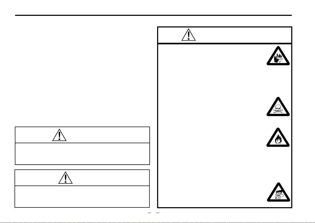
FS-91S2-P
Glow plug Type F
Rocker Cover
Cylinder Head
Push Rod Cover
Propeller Washer
Propeller Nut
Lock Nut
Drive Hub
INSTALLING THE GLOW PLUG
Carefully insert plug, with washer,
fingertight only, before final tightening
with the correct size plug wrench.
Glow plug
Washer
Carburettor Type 60N
5
Beam Mount
Crankcase
Cover Plate
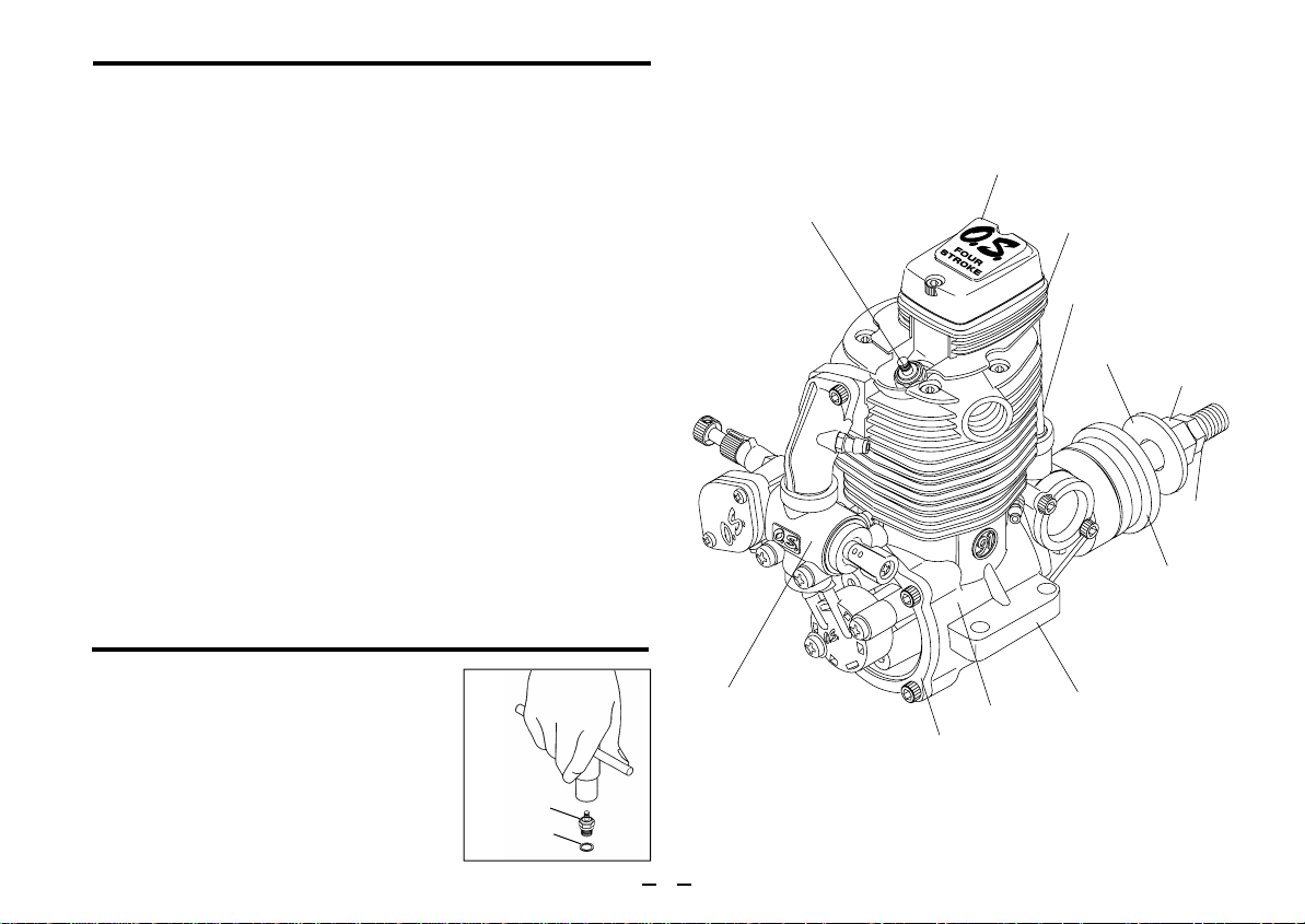
RELOCATION OF CARBURETTOR CONTROLS
FS-91S2-P
As supplied, the FS-70S2, FS-91S2 and FS-91S2-P have their
throttle lever on the right hand side and needle-valve control on
the left. However, where more convenient for certain installations,
these positions may be reversed after rotating the carburettor
through 180˚ horizontally.
Proceed as follows:
1.
Remove the intake pipe mounting screws from the cylinder head
(taking care not to lose the flange gasket [91S2/91S2-P] ) and
the carburettor mounting screws from the crankcase cover plate
bracket.
2.
Detach short tube connecting carburettor to pump unit (FS-91S
-P) and gently rotate the carburettor through 180° without
2
separating it from the intake pipe or removing the enclosed Oring seal.
3.
Re-install the complete sub-assembly of intake pipe and
Pressure Regulator
carburettor, making sure that adjoining surfaces are clean.
Tighten screws evenly and firmly but not excessively.
Remove pump mounting screws from the crankcase cover
4.
plate lugs, carefully rotate the pump clockwise one-quarter turn
and attach it to the second pair of lugs provided, taking care that
the central tube connecting the crank chamber to the pump
diaphragm chamber is not twisted.
Finally, make sure that all external tube connections are secure
5.
and do not leak.
Intake Pipe
Mounting Screw
Intake Pipe
Needle Valve
Carburettor
Mounting Screw
FueI Inlet
Pump Fixing Screw
PD-07 Pump
Throttle Lever
6
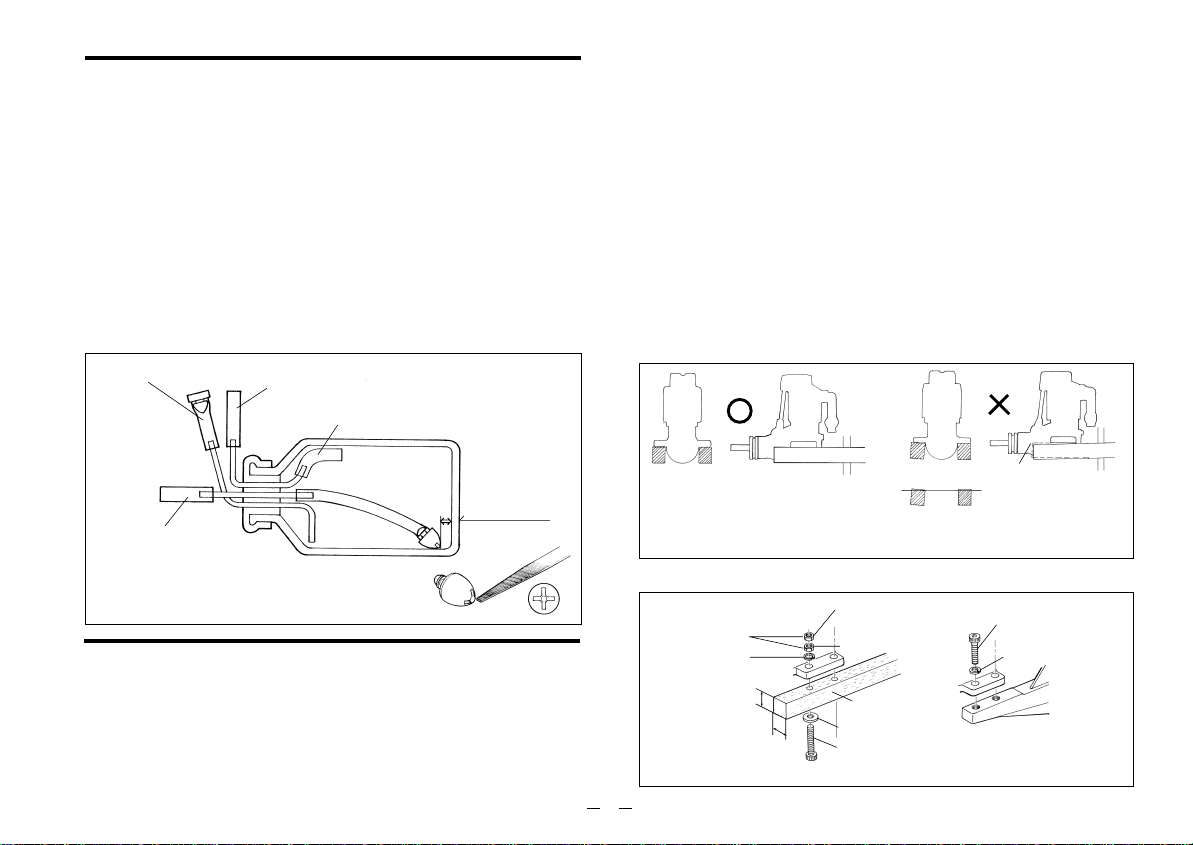
FUEL TANK
A fuel tank of approximately 300cc capacity is suggested. This
allows up to 12-13 minutes flying time, dependent upon the type of
fuel used, the size of the propeller and on the proportion of fullthrottle to part-throttle operation through the flight. Make sure that
the tank is well rinsed out with methanol or glow fuel before
installation and that the pickup weight is well clear of the bottom of
the tank when held vertically (see sketch). To prevent the pickup
from adhering to the tank wall under suction and restricting fuel
flow, slots may be filed in the end of the weight as shown.
Alternatively, a Bubbless type weight (Code No. 71531000) may
be used.
For filling or emptying tank
Air vent
Use thick-walled sillcone tubing
Make sure that these mounting beams are accurately aligned and
firmly integrated with the airframe, reinforcing the adjacent
structure to absorb vibration. Use 3.5mm or larger steel screws,
preferably Allen type hexagon socket head cap screws, with
washers and locknuts, for bolting the engine to the bearers.
As an alter native to wooden beam mounting, a special O.S. cast
aluminium radial motor mount, complete with 3.5mm mounting
screws, is available as an optional extra part, where front bulkhead
(firewall) type mounting is called for. Engine installation should, in
any case, be made in such a way that basic maintenance can be
conveniently carried out.
Make sure that the mounting beams are parallel and that their top
surfaces are in the same plane.
CORRECT
INCORRECT
10~15mm
To fuel inlet
INSTALLATION
Because these are powerful, large-displacement, single-cylinder
four-stroke-cycle engines, it is essential to use very substantial
engine mounting. Conventional wooden mounting beams should
be of rigid hardwood and of at least 15mm or 5/8-in square
section.
Front view
Top surfaces are in the same plane.
How to fasten the mounting screws.
3.5mm steel nuts
Spring washer or
lock washer
15mm min.
Hardwood mounting beams
Side view
15mm min.
7
Top surfaces are not
in the same plane.
Re-align the surfaces
as necessary
Tighten second nut firmly
down onto first nut.
Tighten this nut first.
Hardwood such as
cherry or maple.
Steel washer
4mm steel screw
O.S. radial motor mount
(cast aluminum)
Opposite beam
Top surfaces are not
in the same plane.
Engine does not
rest firmly.
3.5mm steel Allen screw
Spring washer

EXHAUST HEADER PIPE & SILENCER
Fit these in the following sequence.
Screw the header pipe into the cylinder head until it " bottoms
", then unscrew sufficiently to achieve the desired exhaust
angle and tighten the locknut securely with a 14mm wrench.
Screw the silencer onto the outer end of the header pipe and
tighten the other locknut.
The application of a heatproof silicone sealant to the threads of
the exhaust system is recommended to reduce the risk of joints
loosening and the leakage of exhaust gases and oil residue.
Reminder:
Model engines generate considerable heat and contact with
the header pipe or silencer may result in a serious burn.
If you need to tighten the silencer joints, which may loosen
when they are hot, use a thick folded cloth for protection.
NEEDLE-VALVE EXTENSION
The needle-valve supplied with this engine is designed to
accept an extension so that, when the engine is enclosed in a
cowling, the needle-valve may be adjusted from the outside.
An L-shaped rod, of appropriate length, may be inserted in the
needle-valve knob centre hole and secured by tightening the
set-screw with a 1.5mm Allen key.
FUEL LINES
FS-70S2, FS-91S
<
For fuel line, use, heavy-duty silicone-rubber tubing of
approximately 2.5mm inside and 5.0mm outside diameter.
It is advisable to fasten connections with tube clips or secure
binding.
2
>
THROTTLE LINKAGE
Before connecting the throttle to its servo, make sure that the
throttle arm and linkage safely clear any adjacent part of the
airframe structure, etc., as the throttle is opened and closed.
Connect the linkage so that the throttle is fully closed when
the transmitter throttle stick and its trim lever are at their
lowest settings and fully open when the throttle stick is in its
fully-open position..
Carefully align the appropriate holes in the throttle arm and
servo horn so that they move symmetrically and smoothly
through their full travel.
Note:
8
Be sure to use a muffler-pressurized fuel feed
system.
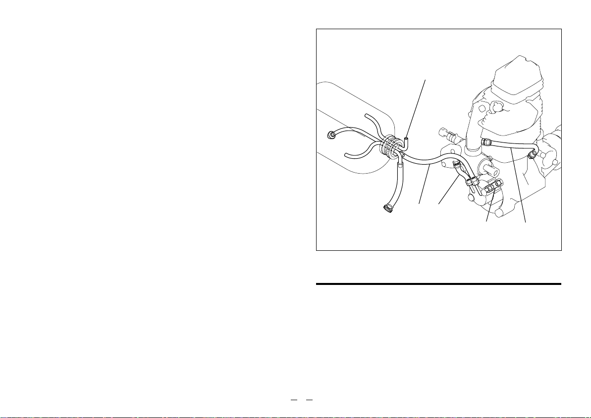
FS-91S2-P
<
The function of the various tubes connected to the engine and
tank (see sketch) are as follows:
Pipe A:
Pipe B:
Pipe C:
Pipe D:
Important
Pipes B, C and D are already installed when the engine is
shipped from the factory. If any of these pipes should
need to be replaced, due to damage or installation
problems, be sure to use tubing of the same dimensions
and quality as the originals.
For Pipe A (tank to pump) use similar heavy-duty siliconerubber tubing of approximately 2.5mm bore and 5.0mm
outside diameter.
Note:
Since the FS-91S2-P has a positively pumped fuel
supply, it does NOT require muffler pressurization.
>
To draw fuel from tank to pump nipple marked 'IN'.
To deliver fuel from pump nipple marked 'OUT' to
carburettor.
To connect crankcase breather nipple (behind
camshaft housing) to intake pipe.
To deliver crankcase pressure pulses to pump dia-
phragm.
Make sure there is adequate ventilation.
AB
D
C
CARE OF FUEL PUMP & REGULATOR
FS-91S2-P
<
A short preliminary period of part-throttle running is required
to ensure that the pump system functions correctly during the
running-in process. Set the throttle 75% open from the fullyclosed position and run the engine for 2-3 minutes. This will
ensure that the engine becomes rich enough when the
needle-valve is opened at full throttle during running-in.
>
9
 Loading...