


It is of vital importance, before attempting to operate your engine, to read the general 'SAFETY INSTRUCTIONS AND WARNINGS'section on pages 2-4 of this booklet and to strictly adhere to the advice contained therein.
 Also, please study the entire contents of this instruction manual, so as to familiarize yourself with the controls and other features of the engine.
 Keep these instructions in a safe place so that you may readily refer to them whenever necessary.
 It is suggested that any instructions supplied with the aircraft, radio control equipment, etc., are accessible for checking at the same time.

SAFETY INSTRUCTIONS AND WARNINGS ABOUT YOUR O.S. ENGINE
Remember that your engine is not a " toy ", but a highly efficient internalcombustion machine whose power is capable of harming you, or others, if it is misused or abused. As owner, you, alone, are responsible for the safe operation of your engine, so act with discretion and care at all times.
If at some future date, your O.S. engine is acquired by another person, we would respectfully request that these instructions are also passed on to its new owner.
 The advice which follows is grouped under two headings according to the degree of damage or danger which might arise through misuse or neglect.
WARNINGS |
These cover events which might involve serious |
(in extreme circumstances, even fatal ) injury. |
|
|
|
These cover the many other possibilities, generally less NOTES obvious sources of danger, but which, under certain
circumstances, may also cause damage or injury.
 WARNINGS
Never touch, or allow any object to come into contact with, the rotating propeller and do not crouch over the engine when it is running.
A weakened or loose propeller may disintegrate or be thrown off and, since propeller tip speeds with powerful engines may exceed 600 feet(180 metres) per second, it will be understood that such a failure could result in serious injury, (see 'NOTES' section relating to propeller safety).
Model engine fuel is poisonous. Do not allow it to come into contact with the eyes or mouth. Always store it in a clearly marked container and out of the reach of children.
Model engine fuel is also highly flammable. Keep it away from open flame, excessive heat, sources of sparks, or anything else which might ignite it. Do not smoke or allow anyone else to smoke, near to it.
Never operate your engine in an enclosed space. Model engines, like automobile engines, exhaust deadly carbon-monoxide. Run your engine only in an open area.
Model engines generate considerable heat. Do not touch any part of your engine until it has cooled. Contact with the muffler(silencer), cylinder head or exhaust header pipe, in particular, may result in a serious burn.
2

 NOTES
NOTES
This engine was designed for model aircraft. Do not attempt to use it for any other purpose.
Mount the engine in your model securely, following the manufacturers' recommendations, using appropriate screws and locknuts.
Be sure to use the silencer (muffler) supplied with the engine. Frequent exposure to an open exhaust may eventually impair your hearing.
Such noise is also likely to cause annoyance to others over a wide area.
Install a top-quality propeller of the diameter and pitch specified for the engine and aircraft. Locate the propeller on the shaft so that the curved face of the blades faces forward-i.e. in the direction of flight. Firmly tighten the propeller nut, using the correct size wrench.
Always check the tightness of the propeller nut and retighten it, if necessary, before restarting the engine, particularly in the case of four- stroke-cycle engines. A safety locknut assembly is provided. Always use it. This will prevent the propeller from flying off in the event of a "backfire", even if it loosens.
If you install a spinner, make sure that it is a precision made product and that the slots for the propeller blades do not cut into the blade roots and weaken them.
Discard any propeller which has become split, cracked, nicked or otherwise rendered unsafe. Never attempt to repair such a propeller: destroy it. Do not modify a propeller in any way, unless you are highly experienced in tuning propellers for specialized competition work such as pylon-racing.
Use an electric starter for this engine. The wearing of safety glasses is also strongly recommended.
Take care that the glow plug clip or battery leads do not come into contact with the propeller.
Also check the linkage to the throttle arm. A disconnected linkage could also foul the propeller.
3

 NOTES
NOTES
Adjust the throttle linkage so that the engine stops when the throttle stick and trim lever on the transmitter are fully retarded. Alternatively, the engine may be stopped by cutting off the fuel supply. Never try to stop the engine physically.
Take care that loose clothing (ties, shirt sleeves, scarves, etc.) do not come into contact with the propeller.
Do not carry loose objects (such as pencils, screwdrivers, etc.) in a shirt pocket from where they could fall through the propeller arc.
Do not start your engine in an area containing loose gravel or sand.
The propeller may throw such material in your face and eyes and cause injury.
For their safety, keep all onlookers (especially small children) well back (at least 20 feet or 6 meters) when preparing your model for flight. If you have to carry the model to the take-off point with the engine running, be especially cautious. Keep the propeller pointed away from you and walk well clear of spectators.
Warning! Immediately after a glowplug-ignition engine has been run and is still warm, conditions sometimes exist whereby it is just possible for the engine to abruptly restart if the propeller is casually flipped over compression WITHOUT the glowplug battery being reconnected. Remember this if you wish to avoid the risk of a painfully rapped knuckle!
4

INTRODUCTION
This is the FS-91S -FI (fuel injection) engine equipped with a revolutionary fuel supply system that was jointly developed by Futaba, a manufacturer of Radio control equipment, and O.S. Engines, a manufacturer of model engines.
This system detects engine speed with a sensor based on throttle signals transmitted from a transmitter. It then determines the fuel injection volume based on the required amount of fuel to be supplied for that engine speed as calculated by an electronic control unit (EC-2<FS- 91S -FI>) referred to as the "EC-2", after which fuel is injected into the engine from an injector. In addition, adjustments can also be made using dial on the transmitter. The result is an engine for sport models that features excellent engine speed linearity relative to throttle operation under all types of flight conditions.
FEATURES
Supplies the Proper Amount of Fuel at all Times
Easier starting
Greater stability during idling
Excellent linearity and response relative to stick operation.
Simple Adjustment Using Dials on the Transmitter
Air-fuel mixture at medium and high speeds can be safety and easily adjusted from the transmitter.
Adjustments can be made while on the ground and during flight.
Stable Supply of Fuel at all Times
Pressurized fuel is controlled at a constant pressure with respect to all types of movement during flight allowing stable engine performance at all times.
Light Weight and Easy Installation
The sensor and injector mounted on the engine are both compact and lightweight, while the electronic control unit (EC-2) is also lightweight, enabling various connections to be made easily the same as plugging in a servo.
5
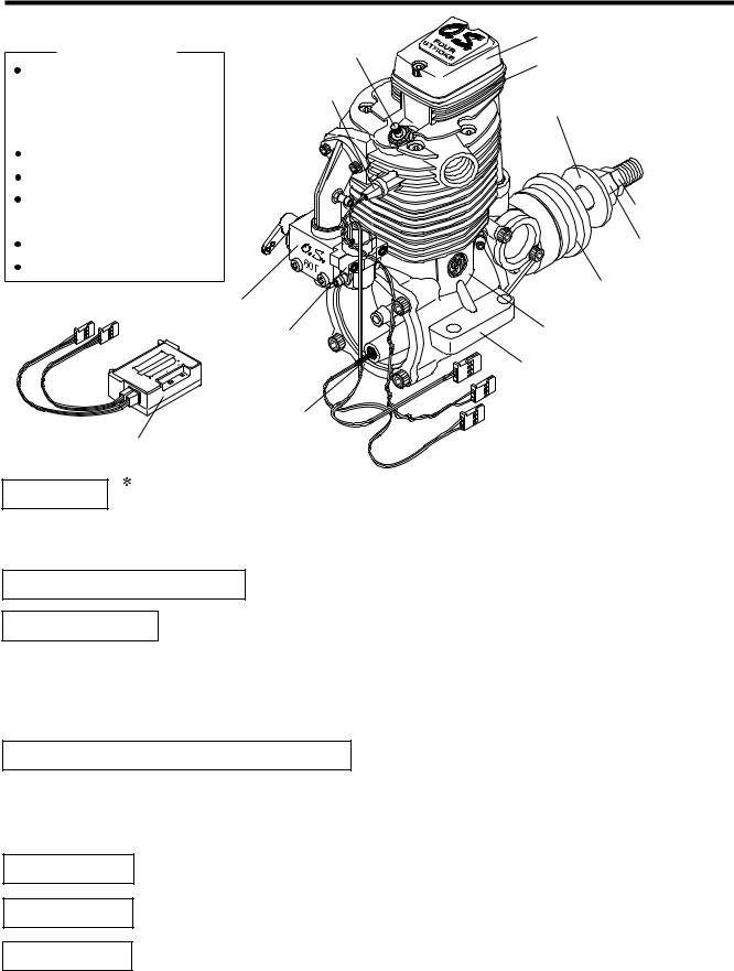
BASIC ENGINE PARTS |
Rocker Cover |
||
Accessories |
Glow plug |
Cylinder Head |
|
EC-2 Assembly |
TYPE F |
||
|
|||
Y harness |
Temperature |
Propeller Washer |
|
Duble-sided sponge- |
Sensor |
||
|
|||
backed cushioning tape |
|
|
|
Check Valve |
|
|
|
Fuel Filter |
|
|
|
Driver to push Limit |
|
Lock Nut |
|
Setting Switch |
|
||
|
|
||
Glow plug TYPE F |
|
Propeller Nut |
|
F-4020 Silencer |
|
|
|
|
Injector |
Drive Hub |
|
|
|
|
Air Valve 60T |
Crankcase |
|
Injector |
|
|
|
|
|
|
Beam Mount |
|
RPM Sensor |
|
Electronic Control Unit<EC-2> |
|
|
Injector |
Never attempt to disassemble the injector. |
|
It may not be able to be reassembled. |
|
|
|
|
|
The injector consists of a solenoid valve with built-in regulator. It controls pressurized fuel at a constant pressure and accurately injects fuel based on signals from the electronic control unit (EC-2).
Temperature Sensor This measures the temperature of the engine exhaust unit.
RPM Sensor
The RPM sensor is provided with a power generating sensor. When the crankshaft passes in front of the sensor, the signal that is generated is transmitted to the electronic control unit (EC-2). Engine rpm are then detocted based on that signal which is then used to determine the timing at which fuel is injected.
Electronic Control Unit<EC-2> (abbreviated as simply EC-2)
The EC-2 transmits fuel injection signals to the injector to ensure the proper amount of fuel injection based on basic fuel injection data that has been previously entered and constantly changes with position of throttle stick.
Check Valve
Fuel Filter
Y harness
This one-way valve's function is to pressurize the fuel tank by crankcase pressure and prevent fuel from returning to the engine crankcase.
This fine mesh filter prevents foreigh matter from the fuel tank from plugging the small injector valve.
This cord is used to connect the receiver (throttle channel), throttle servo and EC-2.
6

CONNECTING WITH THE EC-2
Connect the receiver and servo-related components (rudder section) in the same manner as in the past.
|
(8) Integrated Buzzer |
|
(3) Injector output terminal |
(2) Injection trim input terminal |
(INJECTOR) |
(4) Temperature sensor input |
|
(AUX:TRIM) |
terminal (Temp) |
|
(5) RPM sensor input terminal |
|
(r.p.m.) |
(1) Injection time input terminal
(CH3:THRO)
(6) Limit Setting Switch(LIMIT) (7) L.E.D.
Two extension cords (sold separately) of a length corresponding to the airframe are required for connecting (1) and (2).
(1) Injection Time Input Terminal<Black> (CH3:THRO)
Connect the y harness provided with the CH3 THRO input terminal to throttle channel of the receiver (throttle: CH3), connect the wiring connector from the throttle servo to one of the doubleopening connectors on the opposite side, and connect the other double-opening connector to CH3:THRO of EC-2. (Use the separately sold extension cord if the wiring cords are too short.)
(2) Injection Trim Input Terminal<Red> (AUX:TRIM)
Connect a spare channel for dial use of the receiver (e.g. channel 7) to the AUX:TRIM terminal. (Use the separately sold extension cord if the wiring cords are too short.)
(3) Injector Output Terminal
Connect the injector connector to the injector output terminal. Protect the lead wire with a heatresistant tube,etc. if it makes contact with the engine mount.
(4) Temperature Sensor Input Terminal
Connect the temperature sensor connector to the temperature sensor input terminal.
(5)Rotation Sensor Input Terminal Connect the rotation sensor connector to the rpm input terminal.
(6)Limit Setting Switch(LIMIT) Push with driver supplied when setting limit.
7

(7) L.E.D.(Display of green and red)
It flashes or changes color when setting and cheking limit, and adjusting injection trim. It flashes with the color of the injection trim when the engine is running.
LED Display
|
Transmitter Operation |
LED Status |
|
Turn the dial right to reduce injection volume. |
Red lights |
|
|
|
When the engine |
Turn the dial left to increde injection volume. |
Green lights |
is not running |
|
|
Limit position |
Flashes |
|
|
(color depends or the dial position) |
|
|
|
|
When the engine |
Turn the dial right to reduce injection volume. |
Red flashes |
is running |
Turn the dial left to increde injection volume. |
Green flashes |
|
|
|
 Turning direction of dial shows the standard setting direction.
 Dial position shows plus (green - rich) or minus (red - lean) from the zero position (basic injection volume.)
(8) Integrated Buzzer Buzzer sounds when setting Limit, dial is set nnetral a error happens.
Buzzer notes and status
Notes |
Status |
|
|
Nil |
Normal |
|
|
One note (Pi) |
Limit at Low is set |
|
|
Two successive notes (PiPi) |
Dial neutral |
|
Limit at High is set |
|
|
Repeated one note (Pi...Pi...) |
Temperature Sensor is disconnected |
|
|
Repeated two successive notes (PiPi...PiPi...) |
Error on setting Limit |
|
|
Repeated three successive notes (PiPiPi...PiPiPi...) |
Battery voltage falls down (below 3.8v) |
|
|
mark shows alarm for error. |
|
Fig.1 |
|
Temperature Sensor |
Transmitter |
|
|
Injector |
|
F S |
Branched Cord |
SERIES |
|
Throttle Servo |
|
MADE IN JAPAN |
|
|
|
|
Receiver |
Rotation Sensor |
CH3 |
|
|
|
AUX |
EC-2 |
Spare Channel |
AUX |
|
Throttle Channel |
|
8 |
|

Injection trim adjustment corresponds to needle-valve adjustment of conventional carburetor)
Fuel injection volume
Intermediate slow
 basic injection volume
1 |
2 |
3 |
4 |
5 |
6 |
7 |
8 |
9 |
Fig.2
Full high
Injection trim can be adjusted independently for two area as shown in the graph. Intermediate slow and full high are adjusted with the injection trim adjustment dial (spare channel dial) on the transmitter.
Lo |
Mi |
Hi |
|
(Throttle stick position) |
|
LIST OF FS-91S -FI USAGE CONDITIONS
Part |
Manufacturer |
Name |
|
Remarks |
|
|
|
|
|
|
|
Silencer |
O.S. |
F-4020 |
|
|
|
|
|
|
|
|
|
Glow plug |
O.S. |
TYPE F |
|
|
|
|
|
|
|
|
|
Propeller |
Commercially |
General references: |
Maximun |
speed should |
be |
|
available |
13x9 (Basic propeller) |
between 8,000 and 9,000 rpm. |
|
|
|
high-quality |
13x10-11, 12.5x9 |
|
|
|
|
product |
12x13 |
|
|
|
|
|
14x10 |
|
|
|
|
|
|
|
||
Fuel |
Commercially |
10-25% nitromethane |
Adjustment may vary slightly according to |
||
|
available |
15-20% oil |
the amounts of nitromethane and oil. |
||
|
high-quality |
Use a fuel containing as low nitromethane |
|||
|
|
||||
|
product |
|
as possible within the percentage shown |
||
|
|
|
left. Too much oil may cause malfunction. |
||
|
|
|
|
||
Transmitter |
FUTABA |
1024ZA T9Z |
Spare channel dial (used at 100% by |
||
|
FUTABA |
FF8A |
canceling |
mixing and expo, |
etc. when |
|
used alone. |
|
|||
|
FUTABA |
FF9 |
|
||
|
In case of FUTABA, set with spare |
||||
|
|
|
|||
|
JR |
PCM10S |
channel NORM direcion. |
|
|
|
In case of other marks, it is necessary to |
||||
|
JR |
PCM10X |
|||
|
change setting it the direction is reverse. |
||||
|
JR |
X3810 |
|||
|
|
|
|
||
|
JR |
X378 |
|
|
|
|
|
|
|
|
|
|
|
|
|
|
|
|
SANWA |
STYLUS |
Only Z connectors can be used |
|
|
|
|
RD6000 Super |
(check whether polarity matches). |
||
|
|
|
|
||
Aircraft |
|
Sport |
Wingspan 1.3-1.8m Weight 3-4kg |
||
|
|
|
|
|
|
The contents of the user's manual are based on those products indicated with an asterisk ( ).
9
 Loading...