


XTREME 600.4
OWNER’
HIGH PERFORMANCE CAR AUDIO
TABLE OF CONTENTS
INTRODUCTION |
3 |
|
|
|
|
WARRANTY |
6 |
|
|
|
|
SPECIFICATIONS |
8 |
|
|
|
|
TECHNICAL DESIGN FEATURES |
10 |
|
|
|
|
SYSTEM PLANNING |
12 |
|
|
|
|
INSTALLATION |
18 |
|
|
|
|
POWER CONNECTIONS |
19 |
|
|
|
|
SPEAKER CONNECTIONS |
20 |
|
|
|
|
OUTPUT CONFIGURATIONS |
24 |
|
|
|
|
4-CHANNEL INPUT CONFIGURATIONS |
24 |
|
|
|
|
RCA INPUT / CH 1 & 2 XVR |
25 |
|
|
|
|
INTERNAL CROSSOVER CONFIGURATION |
25 |
|
|
|
|
INTELLI Q |
28 |
|
|
|
|
REMOTE GAIN |
31 |
|
|
|
|
SIGNAL INPUT AND OUTPUT LEVEL CONTROLS |
31 |
|
|
|
|
CHOOSING MOUNTING LOCATIONS |
32 |
|
|
|
|
STEP BY STEP INSTALLATION |
33 |
|
|
|
|
TESTING THE SYSTEM |
35 |
|
|
|
|
ADJUSTING THE SOUND OF THE SYSTEM |
36 |
|
|
|
|
TROUBLESHOOTING TIPS |
38 |
|
|
|
|
AUTOSOUND 2000 TROUBLESHOOTING TIPS |
40 |
|
|
|
|

I N T R O D U C T I O N
Thank you for your purchase of ORION’s XTREME amplifier. Each ORION amplifier is designed to be the leader in its class offering the most power, advanced features and ease of use. The ORION XTREME amplifiers are designed as the best car audio amplifier money can buy. Listed below are the features of the new ORION XTREME amplifiers.
•XTREME 600.4 – 75 watts per channel, 4-channel amplifier with fully variable low-pass crossovers from 45Hz to 5khz. The high-pass crossover is continuously variable from 10Hz to 10kHz. The XTREME 600.4 has the INTELLiQ subwoofer optimizing circuitry and dual remote gain capability. The XTREME 600.4 is capable of 6, 5, 4, 3, or 2 channel operation.
NOTE: The installation of all ORION XTREME amplifiers will determine the overall performance result. Improper installation will not only limit the performance of your ORION system but also potentially compromise the reliability of this digital processor. To ensure proper sonic results and component reliability, please refer to your Authorized ORION dealer for installation assistance or advice. If you decide to perform the installation yourself, read the entire installation section of this manual before beginning the installation.
page 3

ABOUT THIS MANUAL
This manual is divided into different sections for different needs. Whether you are the owner, salesperson or installer, we have devoted sections of this manual to answer your questions. If you just purchased this amplifier and have yet to decide on a system configuration, refer to the System Planning section of this manual for awesome system ideas.
We, at ORION, strive to give you the latest up to date information about our products. What we cannot give you is personal installation or technical experience. If you have questions regarding the installation or the setup or tuning of this product, please refer to your nearest Authorized ORION Dealer for assistance. Additionally, you can call ORION’s Technical Support Hotline at 1-800-315-2052 or 602- 705-5600 for assistance.
PRACTICE SAFE SOUND ™
Continuous exposure to sound pressure levels over 100dB may cause permanent hearing loss. High powered automotive sound systems can generate sound pressure levels in excess of 130dB. When playing your system at high levels, please use hearing protection and avoid long term exposure.
RECORD YOUR SERIAL NUMBER AND DATE:
Model: __________________________________________________________
Serial Number: __________________________________________________________
Date of Purchase: __________________________________________________________
Company Purchased From: __________________________________________________________
page 4

WHAT’S IN THE BOX
(1) XTREME amplifier
(1) 4 gauge power and ground connector
(1) 12 gauge speaker and remote connector
(4) #8 self-tapping black Phillips pan head
(1) XTREME installation and operation
page 5

WARRANTY
ORION Industries Inc. warrants this product to be free from defects in material and workmanship under the following terms:
Parts and Labor are warranted for a period of 3 years IF:
a.The product is purchased from an Authorized ORION Dealer
b.The product is installed by an Authorized ORION Dealer
Parts and Labor are warranted for a period of 1 year IF:
a.The product is purchased from an Authorized ORION Dealer
b.The product is NOT installed by an Authorized ORION Dealer
Parts and Labor are warranted for a period of 90 days IF:
a. The product is NOT purchased from an Authorized ORION Dealer
If you are uncertain as to whether your dealer is authorized, please contact ORION at 1-800-775-7150 or 480-705-5600. In countries other than the USA, each distributor warrants the ORION product it sells.
The following conditions and situations are NOT covered by this warranty:
Any product on which the serial number has been defaced, modified or removed. Damage or malfunction resulting from:
a.Accident, misuse, abuse, unauthorized modification or failure to follow the instructions provided with this product
b.Repair by anyone NOT authorized by ORION
c.Damage due to shipping (these claims must be presented to the freight carrier)
d.Removal or installation of this product
e.Any failure that has NOT been caused by a defect in material or workmanship
page 6
This warranty is in effect for the original purchaser only. ORION will pay for labor and material expense for covered items. ORION does not cover removal or installation charges, payment of shipping charges to ORION, payment of OUT-OF-WARRANTY shipping charges, or damage to other property caused by any defects in this product.
For IN-WARRANTY service, you must include a copy of the original, dated sales receipt, including serial number, from an Authorized ORION Dealer. Please also provide your name, return street address (No P.O. Boxes) and a detailed description of the problem.
For out-of-warranty products, please include ORION E-Z Repair Form. These are available by contacting ORION Repair at 1-888-362-5283 or 480-705-5600 and ask for the Repair Department.
•If you do not have the original packaging, the product must be packaged to prevent damage during shipment.
ORION Industries Inc.
ATTN.: Repair Department
9235 South McKemy Street
Tempe, Arizona 85284 USA
Exclusion
1.This warranty is in lieu of all other warranties expressed or implied.
2.In no event will ORION be liable for any consequential damages resulting from the use of this product or any defect of this product. This warranty gives you specific legal rights. You may also have other rights that vary from state to state.
page 7

SPECIFICATIONS
|
Amplifier Section |
XTREME 600.4 Front Channels |
XTREME 600.4 Rear Channels |
|
|
|
|
||||
|
|
|
|
|
|
|
Power output 4 Ω stereo (watts)1 |
75 x 2 |
75 x 2 |
|
|
|
|
|
75 x 2, 300 x 1 |
75 x 2, 300 x 1 |
|
|
Power output 2 Ω stereo (watts)2 |
150 x 2 |
150 x 4 |
|
|
|
Power output 4 Ω mono (watts)1 |
300 x 1 |
300 x 2 |
|
|
|
Distortion all channels driven |
<0.1% THD |
<0.1% THD |
|
|
|
(from 20Hz to 20kHz) |
|
|
|
|
|
|
|
|
|
|
|
Frequency Response |
20Hz to 20kHz ±0.25dB |
20Hz to 20kHz ±0.25dB |
|
|
|
|
|
|
|
|
|
Linear Bandwidth |
6Hz to 50kHz ±3dB |
6Hz to 50kHz ±3dB |
|
|
|
|
|
|
|
|
|
Signal-to-noise ratio full bandwidth |
>100dB |
>100dB |
|
|
@ rated output power |
|
|
|
||
|
|
|
|
||
Damping factor @ output connector |
>400 at output connector |
>400 at output connector |
|
||
@ full bandwidth |
|
|
|
||
|
|
|
|
||
Slew Rate |
>30Vμs |
>30Vμs |
|
||
|
|
|
|
||
Input Sensitivity3 |
200 mV to 5 Vrms |
200 mV to 5 Vrms |
|
||
Input Impedance |
20 k ohm |
20 k ohm |
|
||
|
|
|
|
||
Fuse Type |
(3) 20 Amp ATC |
(3) 20 Amp ATC |
|
||
|
|
|
|
|
|
page 8
|
Crossover Section3 |
XTREME 600.4 Front Channels |
XTREME 600.4 Rear Channels |
|
|
|
|||
|
Low-Pass Crossover |
Continuously variable |
Continuously variable |
|
|
|
|
|
|
|
Low-Pass Frequency Range |
45Hz to 5kHz |
45Hz to 5kHz |
|
|
|
|
|
|
|
High-Pass Crossover |
Continuously variable |
Continuously variable |
|
|
|
|
|
|
|
High-Pass Frequency Range |
10Hz to 10kHz |
45Hz to 5kHz |
|
|
|
|
|
|
|
High-Pass INTELLiQ Range |
0dB to 10dB of Boost |
n/a |
|
|
|
|
|
|
|
General |
|
|
|
|
|
|
|
|
|
Dimensions |
18”L x 10.25”W x 2.25”H |
18”L x 10.25”W x 2.25”H |
|
|
|
(457mm x 260mm x 57mm) |
(457mm x 260mm x 57mm) |
|
|
|
|
|
|
|
|
|
|
|
1All channels driven, continuous rated 4Ω load, 20Hz to 20,000Hz, >0.1% THD, per input voltage at 12.0VDC.
2All channels driven, continuous rated 2Ω load, 20Hz to 20,000Hz, >0.1% THD, per input voltage at 12.0VDC.
3XTREME amplifiers are designed to accept full 9 Volts RMS input when set to the minimum gain position.
4All crossovers are with a slope rate of 12dB/octave and a “Q” of .0707.
page 9
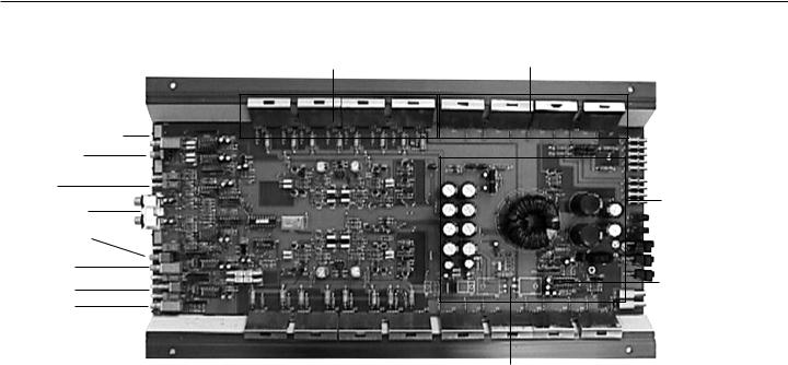
TECHNICAL DESIGN FEATURES
XTREME 600.4
Complementary Matched |
PRS Power supply |
Bipolar Outputs |
MOSFET switches |
Rear Crossover
Rear Gain
2 CH / 4CH
Switch
RCA Input
Front Gain
Front HP
Crossover
INTELLiQ
Front LP
Crossover
Rectifier
Diodes
12 Gauge
Speaker and
Remote
PRS Power
Supply
Remote Gain
ATC Fuse
Power Supply
Controller
4 Gauge Power
& Ground
page 10
TECHNICAL DESIGN FEATURES
1.Power LED - lights up when the amplifier is on
2.Low-pass crossover frequency control-adjusts the front channel low-pass crossover frequency
3.Low-pass crossover switch-activates the front channel low-pass crossover
4.INTELLiQ gain-adjusts the level of INTELLiQ from 0dB to 10dB of boost.
5.High-pass crossover “x10” switch-changes the high-pass crossover frequency range
6.High-pass crossover frequency control-adjusts the front channel high-pass crossover frequency
7.High-pass crossover switch-activates the front channel high-pass crossover
8.Front Gain Control - continuously adjusts from 200mV to 5Vrms for full power output
9.Front Output Configuration Switch - determines the output configuration for the front channels
10.Front RCA Inputsaccepts RCA input from a source unit, preamplifier or equalizer for the front channels
11.Rear RCA Inputsaccepts RCA input from a source unit, preamplifier or equalizer for the rear channels
12.2-Channel / 4-Channel Switch - configures the amplifier for two or four RCA inputs
13.Rear Output Configuration Switch - determines the output configuration for the rear channels
14.Rear Crossover Control - adjusts the frequency for the rear channels
15.Rear channel input configures rear channels for direct input or output of front channel crossover and gain
16.Rear Gain Control - continuously adjusts from 200mV to 5Vrms for full power output
1 |
2 |
3 |
4 |
5 |
6 |
7 |
8 |
9 |
10 |
11 |
12 |
13 |
14 |
15 16 17
18 |
19 |
20 |
21 |
22 |
23 |
17.Rear Crossover Switch - configures the rear channel for highpass, low-pass or full range operation
18.REM Remote Turn-on Input - turns on the amplifier when fed 12 V+
19.Front speaker outputallows up to 12 gauge speaker wire
20.Rear speaker outputallows up to 12 gauge speaker wire
21.Remote Gain-allows dashboard control of the amplifier output level
22.Fuse - protects the amplifier from over current situations
23.Power Connections - allow up to 4 gauge power and ground cables
page 11
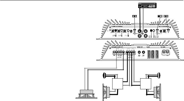
SYSTEM PLANNING
The easiest way to maximize the performance for your ORION XTREME amplifier is to properly plan your system. By planning your system, you can avoid situation where the performance of the reliability of your system is compromised. Your Authorized ORION dealer has been trained by ORION Industries on how to maximize your system’s sonic potential. Authorized ORION dealers are a valuable resource in helping you with your system design and installation. If you wish to venture on with your own system design, here are some systems designed by ORION Industries.
System 1 is a simple two-way system. The front channels are bridged mono for a single 4-ohm subwoofer. The rear channels are configured for stereo operation and high-passed for a set of satellite speakers.
∙Lowest recommended impedance is 2Ω per channel
∙Front channels are configured for summed bridged mono operation
∙Front crossover is configured for low-pass operation
∙Lowest recommended impedance is 4 ohms bridged mono for the front channels.
∙Rear channels are configured for stereo operation
∙Rear crossover is configured for high-pass operation
SYSTEM 1
+ |
+ |
– |
– |
+ |
– |
|
|
||
|
|
|
+ |
– |
+ |
– |
|
|||
|
+ |
||
|
+ |
|
|
|
– |
|
– |
page 12
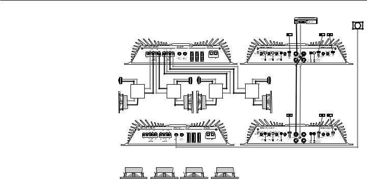
SYSTEM PLANNING
System 2 is a two-way front / rear boomer system. Amplifier 1 powers front and rear separates. Amplifier 2 powers four 4 ohm subwoofers. This system also has a RGC-1 for dashboard control of the bass level.
Amplifier 1
∙Lowest recommended impedance is 2 ohms stereo
∙Front and rear channels configured for stereo operation
∙Front and rear channels set for highpass operation
∙2ch / 4ch input selector configured for 2 channel input
Amplifier 2
∙Lowest recommended impedance in 2 ohms stereo
∙Front and rear channels configured for summed stereo operation
∙Front channels configured for low-pass operation with INTELLiQ.
∙Rear channel input configured from crossover and gain output of channels 1 & 2
∙RGC –1 connected to front gain point controls bass level for entire system.
SYSTEM 2
RGC-1
+ |
+ |
+ |
+ |
– |
+ |
– |
– |
– |
– |
+ |
– |
– |
+ |
|
+ |
– |
+ |
+ |
+ |
|
+ |
– |
– |
– |
|
– |
|
|
|
|
|
|
|
|
|
|
|
|
|
|
|
|
|
|
|
|
|
|
|
|
|
|
|
|
|
|
|
|
|
|
|
|
|
|
|
|
|
|
|
|
|
|
|
|
|
|
|
|
|
|
|
|
|
|
|
|
|
|
|
|
|
|
|
|
|
|
|
|
|
|
|
|
|
|
|
|
|
|
|
|
|
|
|
|
+ |
|
– |
+ |
|
– |
|
– |
|
+ |
|
– |
|
+ |
||||||||
|
|
|
|
|
|
|
|
|
|
|
|
|
|
|
|
|
|
|
|
|
|
|
|
|
|
|
|
|
|
|
|
|
|
|
|
|
|
|
|
|
|
|
|
Note: INTELLiQ is a trademark feature of ORION amplifiers that maximize the performance of any subwoofer system for information regarding the setup of INTELLiQ please refer to the crossover section of this manual that explains INTELLiQ.
page 13

SYSTEM PLANNING
+ |
– |
– |
+ |
|
– |
+ |
+ |
– |
|
|
|
+ |
|
|
+ |
|
|
|
– |
– |
+ |
– |
|
|
|
|
|
||
+ |
– |
+ |
– |
+ |
– |
|
|
|
|||||
|
|
+ |
||||
|
|
|
+ |
|
|
|
|
|
|
– |
|
|
– |
SYSTEM 3
RGC-1
page 14
 Loading...