


HCCA-D1200
HCCA-D2400
HCCA-D5000

CONTENTS
Introduction . . . . . . . . . . . . . . . . . . . . . . . . . . . . . . . . . . . . . . . . . . . . . . . . . . . . . . . . . . . . . . . .2
What’s in the Box . . . . . . . . . . . . . . . . . . . . . . . . . . . . . . . . . . . . . . . . . . . . . . . . . . . . . . .2
Important Note . . . . . . . . . . . . . . . . . . . . . . . . . . . . . . . . . . . . . . . . . . . . . . . . . . . . . . . . . . . . .2
Practice Safe Sound™ . . . . . . . . . . . . . . . . . . . . . . . . . . . . . . . . . . . . . . . . . . . . . . . . . . . . . . . .3
Record Your Serial Number and Date . . . . . . . . . . . . . . . . . . . . . . . . . . . . . . . . . . . . . . . . . . .3
End Panel Layouts . . . . . . . . . . . . . . . . . . . . . . . . . . . . . . . . . . . . . . . . . . . . . . . . . . . . . . . . . . .3
CEA Specifications . . . . . . . . . . . . . . . . . . . . . . . . . . . . . . . . . . . . . . . . . . . . . . . . . . . . . . . . . . .5
Specifications . . . . . . . . . . . . . . . . . . . . . . . . . . . . . . . . . . . . . . . . . . . . . . . . . . . . . . . . . . . . . . .6
Amplifier Settings . . . . . . . . . . . . . . . . . . . . . . . . . . . . . . . . . . . . . . . . . . . . . . . . . . . . . . . . . . .7
Signal Input and Output Configurations . . . . . . . . . . . . . . . . . . . . . . . . . . . . . . . . . . . . .7
Input Gain . . . . . . . . . . . . . . . . . . . . . . . . . . . . . . . . . . . . . . . . . . . . . . . . . . . . . . . . . . . . .7
Phase Switches . . . . . . . . . . . . . . . . . . . . . . . . . . . . . . . . . . . . . . . . . . . . . . . . . . . . . . . . . .7
Line Output Configurations (System Expansion) . . . . . . . . . . . . . . . . . . . . . . . . . . . . . .7
Internal Crossover Configurations . . . . . . . . . . . . . . . . . . . . . . . . . . . . . . . . . . . . . . . . . .7
Low-Pass Crossover . . . . . . . . . . . . . . . . . . . . . . . . . . . . . . . . . . . . . . . . . . . . . . . . . . . . . .8
High-Pass Crossover . . . . . . . . . . . . . . . . . . . . . . . . . . . . . . . . . . . . . . . . . . . . . . . . . . . . . .8
Fine Tuning the Crossovers . . . . . . . . . . . . . . . . . . . . . . . . . . . . . . . . . . . . . . . . . . . . . . . .8
Adjusting INTELLi Q . . . . . . . . . . . . . . . . . . . . . . . . . . . . . . . . . . . . . . . . . . . . . . . . . . . . . .8
Infinite Baffle Example High-Pass Set at 30Hz . . . . . . . . . . . . . . . . . . . . . . . . . . . . . . . .9
Sealed Example High-Pass Set at 20Hz . . . . . . . . . . . . . . . . . . . . . . . . . . . . . . . . . . . . .10
Sealed Example High-Pass Set at 30Hz . . . . . . . . . . . . . . . . . . . . . . . . . . . . . . . . . . . . .10
Vented Example High-Pass Set at 30Hz . . . . . . . . . . . . . . . . . . . . . . . . . . . . . . . . . . . . .10
Remote Gain Operation . . . . . . . . . . . . . . . . . . . . . . . . . . . . . . . . . . . . . . . . . . . . . . . . .11
Amplifier Wiring . . . . . . . . . . . . . . . . . . . . . . . . . . . . . . . . . . . . . . . . . . . . . . . . . . . . . . . . . . .11
Power Connections for the HCCA-D1200, and HCCA-D2400 . . . . . . . . . . . . . . . . . . . .11
Power Connections for the HCCA-D5000 . . . . . . . . . . . . . . . . . . . . . . . . . . . . . . . . . . .11
Speaker Connections . . . . . . . . . . . . . . . . . . . . . . . . . . . . . . . . . . . . . . . . . . . . . . . . . . . .12
Bridging . . . . . . . . . . . . . . . . . . . . . . . . . . . . . . . . . . . . . . . . . . . . . . . . . . . . . . . . . . . . . .12
Amplifier Installation . . . . . . . . . . . . . . . . . . . . . . . . . . . . . . . . . . . . . . . . . . . . . . . . . . . . . . .13
Choosing Mounting Locations . . . . . . . . . . . . . . . . . . . . . . . . . . . . . . . . . . . . . . . . . . . .13
Passenger Compartment . . . . . . . . . . . . . . . . . . . . . . . . . . . . . . . . . . . . . . . . . . . . . . . . .13
Trunk Compartment . . . . . . . . . . . . . . . . . . . . . . . . . . . . . . . . . . . . . . . . . . . . . . . . . . . .13
General Precautions and Installation Tips . . . . . . . . . . . . . . . . . . . . . . . . . . . . . . . . . . .14
Tools of the Trade . . . . . . . . . . . . . . . . . . . . . . . . . . . . . . . . . . . . . . . . . . . . . . . . . . . . . .14
Step By Step Installation . . . . . . . . . . . . . . . . . . . . . . . . . . . . . . . . . . . . . . . . . . . . . . . . .15
Set Up and Troubleshooting . . . . . . . . . . . . . . . . . . . . . . . . . . . . . . . . . . . . . . . . . . . . . . . . . .16
Testing the System . . . . . . . . . . . . . . . . . . . . . . . . . . . . . . . . . . . . . . . . . . . . . . . . . . . . . .16
Adjusting the Sound of the System . . . . . . . . . . . . . . . . . . . . . . . . . . . . . . . . . . . . . . . .16
Troubleshooting Tips . . . . . . . . . . . . . . . . . . . . . . . . . . . . . . . . . . . . . . . . . . . . . . . . . . . .18
Appendix—Programmable Features . . . . . . . . . . . . . . . . . . . . . . . . . . . . . . . . . . . . . . . . . . .20
Notes . . . . . . . . . . . . . . . . . . . . . . . . . . . . . . . . . . . . . . . . . . . . . . . . . . . . . . . . . . . . . . . . . . . . .23
© 2005 Directed Electronics, all rights reserved |
1 |

INTRODUCTION
Thank you for your purchase of Orion's HCCA-D1200, HCCA-D2400, or HCCA-D5000 power amplifier. Each Orion amplifier is designed to be the leader in its class offering the most power, advanced features, and extreme ease of use. In high-end sound systems or high SPL systems, Orion amplifiers will give you years of trouble-free performance.
●HCCA-D1200 - 1200 Watt single-channel Class D amplifier with built-in infrasonic filter, with INTELLi-Q, ESP2, and remote bass. The HCCA-D1200 is capable of one-channel operation with a maximum power of 1200 Watts into 1W.
●HCCA-D2400 - 2400 Watt single-channel Class D amplifier with built-in infrasonic filter, with INTELLi-Q, ESP2, and remote bass. The HCCA-D1200 is capable of one-channel operation with a maximum power of 2400 Watts into 1W.
●HCCA-D5000 - 5000 Watt single-channel Class D amplifier with built-in infrasonic filter, with INTELLi-Q, ESP2, and remote bass. The HCCA-D5000 is capable of one-channel operation with a maximum power of 5000 Watts into 1W.
Each of these amplifiers has security and programmable features controlled via a ESP®-2 serial databus and Directed's proprietary Bitwriter® tool (998T). The Bitwriter® unit must have version 2.3 or above to access the amplifier features menu.
The installation of all Orion components will determine the overall performance result. Improper installation will not only limit the performance of your Orion system but also potentially compromise the reliability of this amplifier. To ensure proper sonic results and component reliability, please refer to your authorized Orion dealer for installation assistance or advice. If you decide to perform the installation yourself, be sure to read the entire manual before beginning the installation.
What’s in the Box
●(1) Amplifier
●(1) Spare fuse(s)
●(1) Allen wrench 2.5mm
●(1) Allen wrench 3mm
●(8) #8 self-tapping black Phillips head pan head screws
●(4) flat washers with adhesive
●(1) 3’ phono cable
●(1) 15’ ESP cable (amplifier to security system cable)
●(1) Amplifier installation and operation manual
●(1) Window decal
IMPORTANT NOTE
Prior to servicing your vehicle ensure that the alarm system is disarmed. Due to the amplifier’s anti-theft feature (if enabled), if the main power to the amplifier is removed while the security system is armed the amplifier operation is disabled. To reset the amplifier, refer to
Appendix—Programmable Features.
2 |
© 2005 Directed Electronics, all rights reserved |
PRACTICE SAFE SOUND™
Continuous exposure to sound pressure levels over 100dB may cause permanent hearing loss. High power automotive sound systems can generate sound pressure levels in excess of 130dB. When playing your system at high levels, please use hearing protection and avoid long term exposure.
RECORD YOUR SERIAL NUMBER AND DATE
To ensure your warranty (see back cover), please record the following information regarding your new amplifier.
Model: __________________________________________________
Serial Number: __________________________________________________
Date of Purchase: __________________________________________________
Purchased from: __________________________________________________
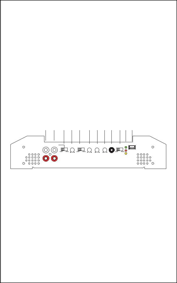
END PANEL LAYOUTS
1 |
2 |
3 |
4 |
|
5 |
6 |
7 |
8 |
9 |
10 11 12 |
|
INPUT |
LINE OUT |
|
|
|
|
|
|
|
|
POWER |
ESP PORT |
|
|
|
|
|
|
|
|
(GREEN) |
|||
L CH |
L CH |
|
GAIN |
INFRASONIC |
HPF |
INTELLI-Q |
LPF |
REMOTE |
PHASE |
|
|
|
|
|
|
||||||||
|
|
|
|
|
|
|
|
|
|
|
PROTECT |
|
|
|
|
|
|
|
|
|
|
|
(RED) |
|
MASTER |
|
SLAVE |
ON |
OFF |
|
|
|
Oº |
180º |
|
|
|
|
MIN MAX |
|
|
20Hz 150Hz |
MIN MAX |
30Hz 250Hz |
|
||
|
|
|
|
|
|
|
|
|
|
ESP |
|
|
|
|
|
|
|
|
|
|
|
INDICATOR |
|
|
|
|
|
|
|
|
|
|
|
(YELLOW) |
|
R CH |
R CH |
|
|
|
|
|
|
|
|
|
|
1.RCA Input - accepts RCA input from a head unit, preamplifier, or equalizer.
2.RCA Line Output - provides easy connection to additional amplifiers.
3.Master/Slave Switch - controls whether the amplifier is a slave or master when connected in combined amplifier configurations. (Refer to the Combined Amplifiers section of this guide.)
4.Gain Control - continuous adjustment for full power output.
5.Infrasonic Switch - when On cuts off extremely low bass frequencies (below the range of human hearing, that speakers cannot effectively reproduce). The high pass filter is engaged when the infrasonic switch is On. This improves efficiency of the amplifier’s power supply, improves sound reproductive performance, and reduces chances of damaging the subwoofers.
6.High-Pass Frequency Control - adjusts the frequency of the high-pass crossover.
7.INTELLi Q Control - continuously adjusts the "Q" boost of the high-pass crossover from 0 to 10dB of boost.
8.Low-Pass Frequency Control - adjusts the upper crossover frequency of the amplifier.
9.Remote Bass Jack - connects optional HP-RB1 remote bass control to control the bass level from the driver’s seat.
© 2005 Directed Electronics, all rights reserved |
3 |

10.Phase Control Switch - provides either 0 or 180 degree phase shift of the amplified output (speaker) with respect to the input signal to facilitate bridging of amplifiers.
11.Power LED - when illuminated (green) indicates that the amplifier is on.
Protect LED - when illuminated (red) indicates that the amplifier protective circuitry has been activated due to thermal, output short, supply undervoltage or supply overvoltage.
ESP® Indicator LED - when illuminated (yellow) indicates ESP® functionality and is used to diagnose ESP® features. The LED flash characteristics will assists in diagnosing the type of fault (see Appendix).
NOTE: The LED on top of the amplifier may also illuminate and flash with the ESP® LED indicator, if this option has been enabled by your installer (requires Bitwriter®).
12. ESP® Port - connection port for Bitwriter® or ESP2 security system.
HCCA-D1200
1 |
2 |
3 |
4 |
5 |
|
|
|
|
SPEAKER |
FUSE |
+BAT |
REM |
GND |
+ + - - |
HCCA-D2400
1 |
2 |
3 |
4 |
5 |
|
|
|
|
SPEAKER |
FUSE |
+BAT |
REM |
GND |
+ + - - |
HCCA-D5000
2 |
3 |
4 |
2 |
3 |
4 |
5 |
|
|
|
|
|
|
SPEAKER |
+BAT |
REM |
GND |
+BAT |
REM |
GND |
+ + - - |
1.ATC Fuse - this fuse(s) protects the amplifier against internal electrical damage and is meant to protect the amplifier only. All other power connections should be fused at the source. The HCCA-D1200 has two 30-amp fuses. The HCCA-D2400 has three 40-amp fuses. The HCCA-D5000 has one inline 250-amp fuse.
4 |
© 2005 Directed Electronics, all rights reserved |
2.+BAT - connect this terminal through a FUSE or CIRCUIT BREAKER to the positive terminal of the vehicle battery or the positive terminal of an isolated audio system battery.
WARNING: Always protect this power wire by installing a fuse or circuit breaker of the appropriate size within 12 inches of the battery terminal connection.
3.REM - this terminal turns on the amplifier when (+) 12 volt is applied. Connect it to the remote turn on lead of the head unit or signal source. If a (+) 12 volt remote turn lead is not available, a Remote Power Adapter (P/N #55000) can be used to supply a remote turn on signal. DO NOT connect this terminal to constant (+) 12 volt.
4.GND - power return connection. Connect this terminal directly to the sheet metal chassis of the vehicle, using the shortest wire necessary to make this connection. Always use wire of the same gauge or larger than the (+) 12 volt power wire. The chassis connection point should be scraped free of paint and dirt. Use only quality crimped and/or soldered connectors at both ends of this wire. DO NOT connect this terminal directly to the vehicle battery ground terminal or any other factory ground points.
5.Speaker - connect the speakers to these terminals. (refer to the Speaker Connection section of this guide.)
NOTE: Make all connections to power, ground, speakers, and remote terminals before final positioning and installation of the amplifier in the vehicle.
NOTE: the HCCA-D5000 has two terminal strips for power connections. The +BAT and GND connections can be made to either of these terminals.
CEA SPECIFICATIONS
HCCA-D1200
Power Output: 250 Watts RMS x 1 at 4 ohms and < 1% THD+N
Signal to Noise Ratio: -60 dBA (reference 1 Watt into 4 ohms)
Additional Power Output: 600 Watts RMS x 1 at 1 ohm at 14.4 Supply<1% THD+N
HCCA-D2400
Power Output: 450 Watts RMS x 1 at 4 ohms and < 1% THD+N
Signal to Noise Ratio: -60 dBA (reference 1 Watt into 4 ohms)
Additional Power Output: 1200 Watts RMS x 1 at 1 ohm at 14.4 Supply<1% THD+N
HCCA-D5000
Power Output: 1000 Watts RMS x 1 at 4 ohms and < 1% THD+N
Signal to Noise Ratio: -60 dBA (reference 1 Watt into 4 ohms)
Additional Power Output: 2500 Watts RMS x 1 at 1 ohm at 14.4 Supply<1% THD+N
© 2005 Directed Electronics, all rights reserved |
5 |

SPECIFICATIONS
Amplifier Section |
HCCA-D1200 |
HCCA-D2400 |
HCCA-D5000 |
|
|
|
|
|
|
Power Output 4W |
250 x 1 |
450 x 1 |
1000 x 1 |
|
(Watts)1 |
||||
|
|
|
||
Power Output 2W |
400 x 1 |
800 x 1 |
1600 x 1 |
|
(Watts)2 |
||||
|
|
|
||
Power Output 1W |
600 x 1 |
1200 x 1 |
2500 x 1 |
|
(Watts) |
||||
|
|
|
||
|
|
|
|
|
Amplifier |
> 70% into 1W load |
> 70% into 1W load |
> 70% into 1W load |
|
Efficiency |
at max. power |
at max. power |
at max. power |
|
Externally |
yes |
yes |
yes |
|
Bridgeable |
||||
|
|
|
||
|
|
|
|
|
Remote Bass |
yes (HP-RB1 |
yes (HP-RB1 |
yes (HP-RB1 |
|
Function |
supplied) |
supplied) |
supplied) |
|
|
|
|
|
|
Distortion at |
< 1.0% THD+N |
< 1.0% THD+N |
< 1.0% THD+N |
|
Rated Power |
||||
|
|
|
||
|
|
|
|
|
Frequency |
20Hz to 250Hz |
20Hz to 250Hz |
20Hz to 250Hz |
|
Response |
±2.5dB |
±2.5dB |
±2.5dB |
|
|
|
|
|
|
Linear Bandwidth |
10Hz to 500Hz |
10Hz to 500Hz |
10Hz to 500Hz |
|
±3dB |
±3dB |
±3dB |
||
|
||||
|
|
|
|
|
Damping Factor |
> 200 |
> 200 |
> 200 |
|
|
|
|
|
|
Input Sensitivity |
150mV to 5V rms |
150mV to 5V rms |
150mV to 5V rms |
|
|
|
|
|
|
Supply Voltage |
9 to 16V |
9 to 16V |
9 to 16V |
|
Range |
||||
|
|
|
||
|
|
|
|
|
|
thermal, DC offset, |
thermal, DC offset, |
thermal, DC offset, |
|
|
reverse polarity, |
reverse polarity, |
reverse polarity, |
|
Protection |
short protection, |
short protection, |
short protection, |
|
|
under-voltage, |
under-voltage, |
under-voltage, |
|
|
over-voltage |
over-voltage |
over-voltage |
|
|
|
|
|
|
|
Power 0/1 AWG, |
Power 0/1 AWG, |
Power 0/1 AWG, |
|
Terminal Wire |
Remote 12 AWG, |
Remote 12 AWG, |
Remote 12 AWG, |
|
Gauge |
Ground 0/1AWG, |
Ground 0/1AWG, |
Ground 0/1AWG, |
|
|
Speaker 12 AWG |
Speaker 12 AWG |
Speaker 12 AWG |
|
Input Impedance |
20kW |
20kW |
20kW |
|
|
|
|
|
|
Fuse Type |
(2) 30 Amp |
(3) 40 Amp |
In-line 250 Amp |
|
|
|
|
|
|
Dimensions |
13"x10.5"x2.3" |
13"x10.5"x2.3" |
13"x10.5"x2.3" |
|
|
|
|
|
|
Weight |
8 lbs. |
8 lbs. |
8 lbs. |
|
|
|
|
|
|
|
Crossover Section |
|
||
|
|
|
|
|
High Pass |
Continuously |
Continuously |
Continuously |
|
Crossover |
variable (20-150Hz) |
variable (20-150Hz) |
variable (20-150Hz) |
|
|
|
|
|
|
Low Pass |
Continuously |
Continuously |
Continuously |
|
Crossover |
variable (30-250Hz) |
variable (30-250Hz) |
variable (30-250Hz) |
|
|
|
|
|
|
|
Selectable On/Off |
Selectable On/Off |
Selectable On/Off |
|
Infrasonic Filter |
24dB/Octave |
24dB/Octave |
24dB/Octave |
|
|
-6dB at 20Hz |
-6dB at 20Hz |
-6dB at 20Hz |
|
|
|
|
|
|
Intelli-Q |
0–10dB boost |
0–10dB boost |
0–10dB boost |
|
|
|
|
|
|
1.Continuous 4W load 20Hz to 200Hz, < 1% THD, with input voltage at 14.4VDC.
2.Continuous 2W load 20Hz to 200Hz, < 1% THD, with input voltage at 14.4VDC.
6 |
© 2005 Directed Electronics, all rights reserved |

AMPLIFIER SETTINGS
Signal Input and Output Configurations
The input section of the amplifier consists of a phase switch that sets the output configuration, infrasonic switch, gain controls, high pass and low pass crossovers controls, Intelli-Q control, and RCA inputs. The input section makes it easy to adapt this amplifier to most system configurations.
Input Gain
These Orion amplifiers have level adjustments to allow for easy integration with any source unit. The input sensitivity can be adjusted from 150mV to 5V. Refer to Testing the System and Adjusting the Sound of the System sections of this guide for detailed instructions on setting the gain.
Phase Switches
●0° - leaves output unaffected. The output signal is in phase with the input signal.
●180° - inverts the output. The channel is 180° output of phase. This configuration is useful for inverting the phase of subwoofers to improve staging in a vehicle. This is also used when bridging two amplifiers into one speaker.
Line Output Configurations (System Expansion)
NOTE: When expanding your system by adding additional Orion amplifiers in the signal chain use only the same model(s) as the first amplier in the chain.
The line outputs on Orion amplifiers offer easy, unlimited system expansion. Routing signal from a source unit, pre-amplifier, or equalizer is a matter of connecting RCAs to the RCA Inputs of the first Orion amplifier and then the RCA line outputs to the next Orion amplifier’s RCA line inputs in the signal chain. Then the Master/Slave switch on each of the amplifers is set as follows:
The first amplifier in the signal chain will have its Master/Slave switch set to the MASTER position. In effect this first amplifier will set the gain for the remainder of the amplifiers in the signal chain.
The remaining amplifiers following in the signal chain will have their Master/Slave switch set to the SLAVE position. This allows the signal to be input directly, bypassing the subsequent amplifiers gain control. The audio level is set and supplied by the output of the master amplifier at its gain setting.
Internal Crossover Configurations
The crossover section of the Orion HCCA-D1200, HCCA-D2400, and HCCA-D5000 amplifiers is continuously variable and extremely flexible. In addition to the variable built-in low-pass filters, the high-pass crossover incorporates the INTELLi Q feature. This circuit is designed to optimize the performance of Orion subwoofers in all types of enclosures.
When using Orion loudspeakers, minor deviations from the recommended frequency ranges can provide superior results depending on your speaker locations and your vehicle acoustics. Setting crossover frequencies higher than recommended will not cause damage and may provide superior sonic results depending on your system's performance goals. Refer to your loudspeaker owner's manual for assistance in choosing the proper crossover frequencies for your system.
© 2005 Directed Electronics, all rights reserved |
7 |
 Loading...