


instruction Manual
Orion® SkyView Pro
GoTo System
#7817
|
|
|
|
|
Customer Support (800) 676-1343 |
|
|
|
|
|
|
|
|
|
|
|
E-mail: support@telescope.com |
|
|
|
|
|
|
|
|
|
|
|
|
|
|
|
|
|
Corporate Offices (831) 763-7000 |
|
|
|
|
|
|
Providing Exceptional Consumer Optical Products Since 1975 |
89 Hangar Way, Watsonville, CA 95076 |
||||
IN 296 Rev. B 02/09

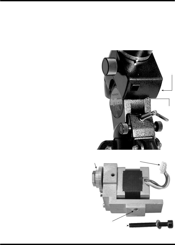
R.A. GoTo motor cover
Motor control box bracket
GoTo hand controller bracket
Motor control box
Motor cables 
Dec. GoTo motor
Dec. GoTo motor cover
 R.A. GoTo motor
Brass gears
GoTo hand controller
GoTo hand controller cable
Figure 1. The SkyView Pro GoTo System (not all parts on parts list are shown)
2
Congratulations on your purchase of the Orion SkyView Pro GoTo system. The GoTo system will add brains to your SkyView Pro equatorial mount’s brawn. Once the GoTo system has been installed, it enables you to locate and automatically slew to thousands of celestial objects using the included hand controller. Views of the planets, Moon, galaxies, nebulae, stars, and star clusters will all be as close as the touch of a button. You’ll find using your SkyView Pro GoTo mount will provide an entirely new astronomical experience that will open up new realms of celestial exploration.
These instructions will help you install and properly use the SkyView Pro GoTo system. Please read them over thoroughly before getting started. It may take a few observing sessions to become familiar with all the features of the SkyView Pro GoTo mount, so keep this manual handy as you master your mount’s operation.
1. Parts List
Qty. |
Description |
1 |
Declination (Dec.) GoTo motor assembly |
1Right ascension (R.A.) GoTo motor assembly
2Brass gears w/ 2mm socket-head set screws
1Motor control box
1Motor control box bracket
1GoTo hand controller
1GoTo hand controller cable (coiled, 30")
1GoTo hand controller bracket
1 |
Motor Cable (13"): motor control box-to-R.A. motor |
1 |
Motor Cable (27"): R.A. motor-to-Dec. motor |
1 |
Hand controller-to-PC cable (5') |
1 |
12V DC power cable |
1 |
Declination (Dec.) motor cover |
1 |
Right ascension (R.A.) motor cover |
1Right ascension (R.A.) motor attachment screw (40mm length)
1Declination (Dec.) motor attachment screw (17mm length)
1Phillips screw (10mm length)
2Phillips screws (8mm length)
2 flat washers, 10mm outer diameter
1 lock washer, 9mm outer diameter
1 4mm hex key
1 2mm hex key
1 Phillips screwdriver
2. Installation
Attaching the R.A. GoTo Motor
Remove the telescope tube, counterweight, and counterweight shaft from the SkyView Pro mount before attaching the motor drives.
1.Remove the R.A. motor cover from the mount by loosening the Phillips head screw on the bottom of the cover (Figure 2). Slide the cover off the mount.
R.A. motor cover
Phillips-head
screw
Figure 2. The R.A. motor cover |
|
Smaller gear |
4-pin rectangular connectors |
|
Attachment hole
 R.A. GoTo motor attachment screw
Figure 3. The R.A. GoTo motor assembly
3
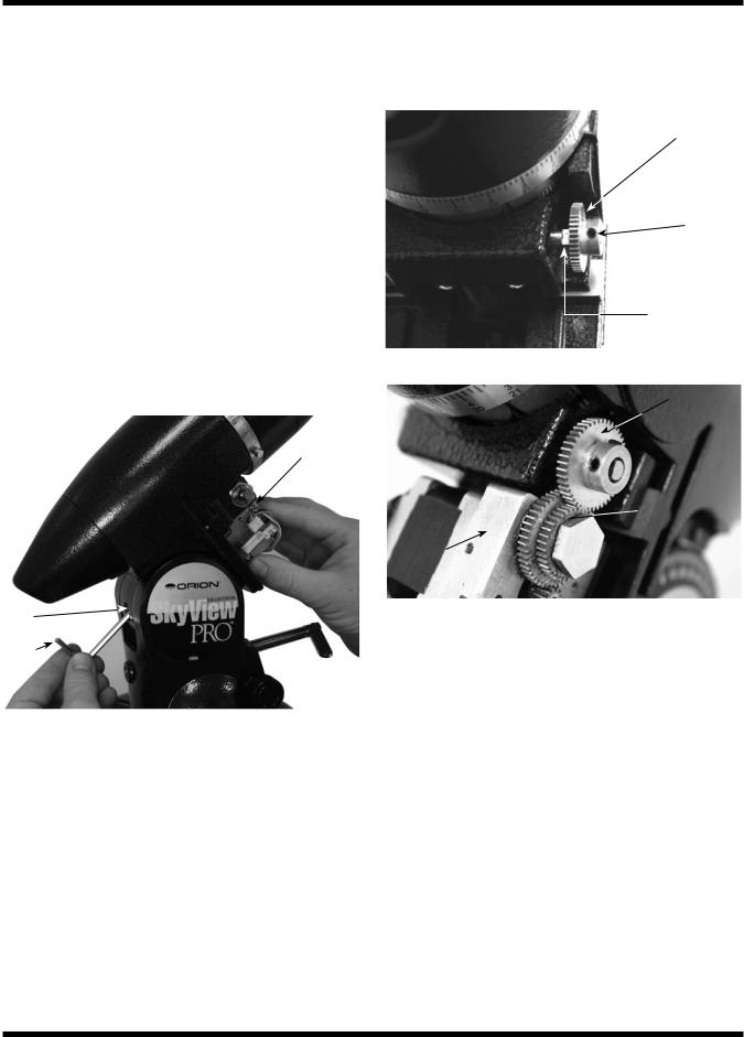
2.Remove the R.A. slow-motion control knob from the R.A. worm gear shaft. The slow-motion knob will not be usable once the SkyView Pro GoTo system has been installed. All slow-motion adjustments will be made using the GoTo hand controller.
3.The R.A. GoTo motor assembly is identified by the 4-pin rectangular connector attached to the motor body (Figure 3). The motor will be attached to the mount by a 40mm long socket-head cap screw that goes through the hole in the rear of the equatorial mount, just above the rear latitude adjustment L-bolt (Figure 4). It will be helpful to remove the rear latitude adjustment L-bolt while installing the R.A. GoTo motor. Place one of the 10mm flat washers onto the R.A. motor attachment screw. Attach the R.A. motor attachment screw to the end of a 4mm hex key and push it up through the hole in the rear of the equatorial mount (Figure 4). Hold the R.A. GoTo drive in your hand so its threaded hole meets the screw as it comes out the other end of the hole. Thread the screw into the threaded hole of the R.A. motor assembly until secure, but do not overtighten. You will need to make small adjustments to the motor position in the following steps.
R.A. GoTo
motor
together, then the drive will not track properly, or at all. This attachment process is tricky, and it may take several adjustments before the gears properly mesh.
Brass gear
Setscrew
R.A. worm gear shaft
Figure 5. Correct orientation of brass gear for R.A. axis
Brass gear
Small R.A. GoTo
R.A.  motor gear
GoTo motor
Hole
4mm hex key
Figure 4. Attaching the R.A. GoTo motor
4.Slide the geared end of one of the small brass gears onto the worm gear shaft so it resembles Figure 5. Rotate the small brass gear so that one of the setscrews will press against the flat part of the R.A. worm gear shaft. Secure the small brass gear by tightening the setscrews with the included 2mm hex key, but do not overtighten. You may have to make small adjustments to the gear’s position in the following step to ensure proper gear engagement.
5.Make certain that the teeth of the smaller motor assembly gear correctly mesh with the teeth of the brass gear (Figure 6). Also, make certain the gears are not too tightly pressed together. You may have to adjust the way the gears mesh by tightening or loosening the socket-head cap screw that is used to attach the R.A. GoTo motor assembly to the mount and/or the small setscrews on the brass gear. If the gears are not meshed correctly or are too tightly pressed
Figure 6. Correctly meshed gears (R.A.)
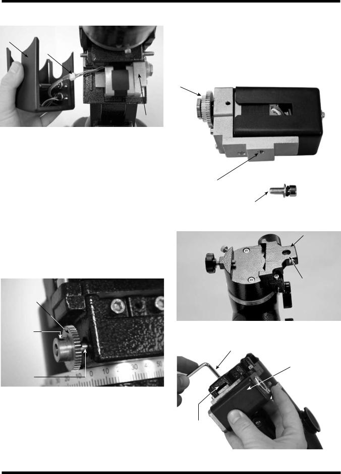
6.Take the R.A. GoTo motor cover and hold it near the installed R.A. GoTo motor. On the inside of the motor cover, you will see a set of wires with a white 4-pin rectangular connector attached. Carefully connect the 4-pin rectangular connector attached to the R.A. GoTo motor cover to the corresponding 4-pin rectangular connector on the R.A. GoTo motor. Once connected, the wiring of your R.A. GoTo motor should resemble Figure 7.
Note: Inside the R.A. GoTo motor cover you will find an additional set of wires connected to each other with 5-pin rectangular connectors. Make certain these wires are connected before proceeding to step 7.
7.Once the rectangular connector has been attached, you can install and secure the R.A. GoTo motor cover with the 10mm long Phillips head screw. Don’t forget to re-install the rear latitude adjustment L-bolt if you have removed it previously.
Note: There is a small packet of grease included with your SkyView Pro GoTo system. Once you have installed the GoTo motor so the gears mesh properly, you can apply a very small amount of the included grease to the meshed gears to ensure optimal gear mating.
4
R.A. GoTo |
Connected |
motor cover |
4-pin |
|
rectangular |
|
connectors |
R.A. GoTo motor
Figure 7. R.A. GoTo motor wiring
Attaching the Dec. GoTo Motor
Before attaching the Dec. GoTo motor drive, the telescope tube must be removed from the equatorial mount.
1.Remove the Dec. slow-motion control knob from the Dec. worm gear shaft. The Slow-motion knob will not be usable once the SkyView Pro GoTo system has been installed. All slow-motion adjustments will be made using the GoTo hand controller.
2.Slide the geared end of the remaining small brass gear onto the Dec. worm gear shaft of your SkyView Pro mount so it resembles Figure 8. Rotate the small brass gear so that one of the setscrews will press against the flat part of the Dec. worm gear shaft. Secure the small brass gear by tightening the setscrews with the included 2mm hex key, but do not overtighten. You may have to make small adjustments to the gear’s position in the following step to ensure proper gear engagement.
Brass gear
Setscrew
Dec. worm gear shaft
Figure 8. Correct orientation of brass gear for Dec. axis
3.The Dec. GoTo motor assembly is identified by its black, rectangular body (Figure 9). It is attached to the equatorial mount using the Dec. GoTo motor attachment screw that goes through the hole in the flange at the top of the equatorial mount (Figure 10). The motor assembly should attached so that it is oriented as shown in Figure 11. Hold the motor assembly so that its threaded hole lines up with the hole in the top of the mount. Place the lock washer and
then a flat washer onto the Dec. GoTo motor attachment screw. Use the 4mm hex key to thread the attachment screw into the motor assembly attachment hole until it is secure, but do not overtighten.
Smaller gear
Attachment hole
Dec. GoTo motor attachment screw
Figure 9. The Dec. GoTo motor assembly
Flange
Hole
Figure 10. The location of the flange on the mount
4mm hex key
Dec. GoTo motor
Flange
Figure 11. Attaching the Dec. GoTo motor
5
4.Make certain that the teeth of the smaller gear of the Dec. GoTo motor assembly meshes with the brass gear. Also, make certain the gears are not too tightly pressed together. You can adjust the way the gears mesh by tightening or loosening the socket-head cap screw that is used to attach the Dec. GoTo motor assembly to the mount and/or the small setscrews on the brass gear. If the gears are not meshed correctly or are too tightly pressed together, then the drive will not track properly, or at all. This attachment process is tricky, and it may take several adjustments before the gears properly mesh.
Note: There is a small packet of grease included with your SkyView Pro GoTo system. Once you have installed the GoTo motor so the gears mesh properly, you can apply a very small amount of the included grease to the meshed gears to ensure optimal gear mating.
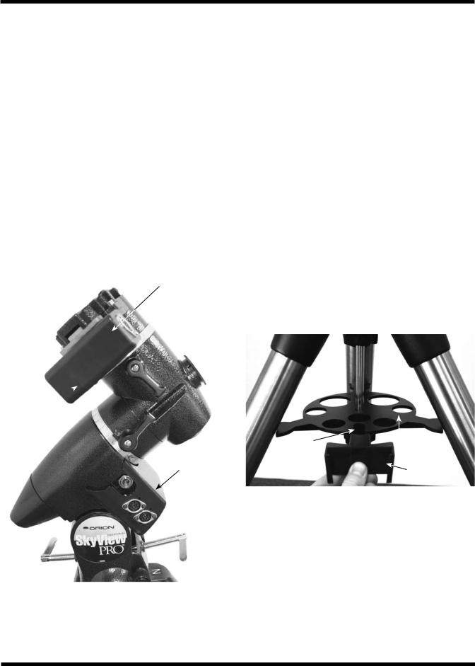
5.Once the Dec. GoTo motor and gear have been installed and the gears mesh appropriately, you can install and secure the Dec. GoTo motor cover with the two 8mm long Phillips screws. Once you have installed the Dec. GoTo motor and cover, your mount should resemble Figure 12.
Dec. GoTo motor
1.Attach the motor control box bracket to the top of one of the legs of the SkyView Pro tripod. It will be most convenient to attach the bracket to the leg closest to the side of the R.A. GoTo motor cover with the two 8-pin circular jacks.
2.Slide the motor control box into the motor control box bracket.
3.Connect one end of the 13" long motor cable to the 8- pin circular jack marked “R.A. IN” on the R.A. GoTo motor cover.
4.Connect the other end of the 13" long motor cable to the 8-pin circular jack on the motor control box.
5.Connect one end of the 27" long motor cable to the 8-pin circular jack marked “Dec. OUT” on the R.A. GoTo motor cover.
6.Connect the other end of the 27" long motor cable to the 8-pin circular jack on the Dec. GoTo motor.
Attaching the GoTo hand controller
1.The included GoTo hand controller bracket attaches to the built-in notch in the tripod center support tray. To install the hand controller bracket, simply line up the tab on the back of the bracket with the notch in the tripod center support tray and slide the bracket forward until it clicks into place (Figure 13). You now have a convenient place to put the GoTo hand controller while you are viewing.
Dec. GoTo  motor cover
R.A. GoTo motor cover
Figure 12. Installed GoTo motors
Attaching the Motor Control Box
Once both of the GoTo motors have been installed, you can attach and connect the motor control box.
Notch |
|
Tripod center |
|
||
|
|
support tray |
|
|
Hand controller |
|
|
bracket |
Figure 13. Installing the GoTo hand controller bracket
2.The SkyView Pro GoTo hand controller cable is a 30" long coiled cable with modular connectors (RJ-45) on both ends. Connect one end of the coiled cable to the modular jack on the motor control box marked “Hand Controller.”
3.Connect the other end of the coiled cable to the hand controller modular jack (Figure 14).
Your SkyView Pro GoTo system is now installed and should resemble the image on the manual cover. You can now proceed to power the system and utilize the many functions of the GoTo hand controller.
6
 Loading...