

Page 1
Brushless Motor
BLH
Series
Digital Setting Type
OPERATING MANUAL
Thank you for purchasing an Oriental Motor product.
This Operating Manual describes product handling procedures and safety precautions.
•Please read it thoroughly to ensure safe operation.
•Always keep the manual where it is readily available.
Table of contents
HP-5073-2
1 Introduction ..........................................................2
2 Safety precautions ..............................................3
3 Precautions for use .............................................4
4 Preparation ............................................................5
4.1 Checking the product .............................................. 5
4.2 How to identify the product model.................... 5
4.3 Information about nameplate .............................. 5
4.4 Products possible to combine .............................. 5
4.5 Names and functions of parts .............................. 6
5 Installation .............................................................7
5.1 Installation location .................................................. 7
5.2 Installing the driver .................................................. 7
6 Connection ............................................................8
6.1 Connecting the motor and driver (CN3) ........... 8
6.2 Connecting the power supply (CN1).................. 8
6.3 Grounding ................................................................... 9
6.4 Connecting the I/O signals (CN2) ........................ 9
6.5 Driver I/O circuit .......................................................10
6.6 Connecting external analog setting
devices ........................................................................11
6.7 Connecting the USB cable (CN4) .......................11
6.8 Connection diagram ..............................................12
6.9 Noise measures ........................................................13
6.10 Conformity to the EMC Directive .......................13
6.11 I/O signals list ............................................................15
7 Operation ............................................................ 16
7.1 Guidance ....................................................................16
7.2 Setting the rotation speed ...................................16
7.3 Setting the acceleration time and
deceleration time ....................................................17
7.4 Operation and stop ................................................18
7.5 Rotation direction of the motor output
shaft .............................................................................19
7.6 Multi-motor control ................................................20
8 Maintenance and inspection ....................... 21
8.1 Inspection .................................................................. 21
8.2 Warranty .....................................................................21
8.3 Disposal ......................................................................21
9 Troubleshooting ...............................................22
10 Alarms ................................................................... 24
10.1 Alarm reset ................................................................24
10.2 Alarm history ............................................................24
10.3 Alarm lists ................................................................... 25
11 Specications ..................................................... 26
11.1 Specications ............................................................26
11.2 General specications ...........................................26
11.3 Dimension..................................................................26
12 Regulations and standards ...........................27
12.1 UL Standards and CSA Standards ......................27
12.2 EU Directives .............................................................27
12.3 Republic of Korea, Radio Waves Act ................. 27
12.4 RoHS Directive .......................................................... 27
Page 2

Introduction
1 Introduction
Before using the product
Only qualied personnel of electrical and mechanical engineering should work with the product.
Use the product correctly after thoroughly reading the section "2 Safety precautions." In addition, be sure to observe the
contents described in warning, caution, and note in this manual.
The product described in this document has been designed and manufactured to be incorporated in general industrial
equipment. Do not use for any other purpose. For the power supply, use a DC power supply with reinforced insulation
on its primary and secondary sides. Oriental Motor Co., Ltd. is not responsible for any damage caused through failure to
observe this warning.
Operating manuals for the product
Operating manuals for the
The USER MANUAL does not come with the product. For details, contact your nearest Oriental Motor sales oce or
download from Oriental Motor Website Download Page.
Type of operating manual Overview
Digital Setting Type
OPERATING MANUAL (this document)
Series are listed below.
BLH
This manual explains the function, installation and connection methods,
troubleshooting, and others for the driver.
Digital Setting Type
USER MANUAL
motor OPERATING MANUAL
BLHM
(included with the motor)
This manual explains detailed operations, functions and others which are not
described in the operating manual included with the product.
This manual explains the functions as well as the installation method and others
for the motor.
2
Page 3
2 Safety precautions
WARNING
CAUTION
WARNING
CAUTION
The precautions described below are intended to ensure the safe and correct use of the product, and to prevent
the customer and others from exposure to the risk of injury. Use the product only after carefully reading and fully
understanding these instructions.
Handling the product without observing the instructions that accompany a "WARNING" symbol may result
in serious injury or death.
Handling the product without observing the instructions that accompany a "CAUTION" symbol may result
in injury or property damage.
Note
The items under this heading contain important handling instructions that the user should observe to
ensure safe use of the product.
Safety precautions
Explanation of graphic symbols
•Do not use the product in explosive or corrosive environments, in the presence of ammable gases, locations subjected to
splashing water, or near combustibles. Doing so may result in re or injury.
•Do not forcibly bend, pull, or pinch the cable. Doing so may result in re.
•Do not use in a vertical application. When the driver protective function is activated, the motor will stop operating. The
moving parts may drop, leading to injury or damage to equipment.
•Do not disassemble or modify the motor, gearhead or driver. Doing so may cause injury. Refer all such internal inspections
and repairs to the branch or sales oce from which you purchased the product.
•Only qualied and educated personnel should be allowed to perform installation, connection, operation and inspection/
troubleshooting of the product. Handling by unqualied and uneducated personnel may result in re, injury or damage to
equipment.
•If the driver protective function was activated, remove the cause before canceling the alarm. Continuing the operation
without removing the cause of the problem may cause malfunction of the motor, leading to injury or damage to equipment.
•Install the motor, gearhead and driver in an enclosure. Failure to do so may result in injury.
•Always keep the power supply voltage of the driver within the specied range. Failure to do so may result in re.
•Connect the cables securely according to the wiring example. Failure to do so may result in re.
•For the driver power supply, use a DC power supply with reinforced insulation on its primary and secondary sides. Failure to
do so may result in electric shock.
•Turn o the driver power in the event of a power failure. Otherwise, the motor may suddenly start when the power is restored,
causing injury or damage to equipment.
Indicates "prohibited" actions that must not
be performed.
Indicates "compulsory" actions that must be
performed.
•Do not use the product in conditions exceeding the motor, gearhead or driver specications. Doing so may result in injury or
damage to equipment.
•Do not touch the motor and driver during operation or immediately after stopping. The surface is hot, and this may cause a
skin burn(s).
•Do not move the product by holding the output shaft of the motor or the gearhead, or the motor cable. Doing so may cause
the product to drop, leading to injury.
•Keep the area around the motor and driver free of combustible materials. Failure to do so may result in re or a skin burn(s).
•Do not leave anything around the motor and driver that would obstruct ventilation. Doing so may result in damage to
equipment.
•Do not touch the rotating part (output shaft) while operating the motor. Doing so may cause injury.
•Do not start or stop the motor operation by switching on or o the power supply. Use the operation input signals of the
driver to operate the motor. Starting and stopping by power-on/o may cause injury or damage to equipment.
•Provide a cover over the rotating part (output shaft) of the motor and gearhead. Failure to do so may result in injury.
•Use a motor and driver only in the specied combination. An incorrect combination may cause a re.
•Provide an emergency stop device or emergency stop circuit external to the equipment so that the entire equipment will
operate safely in the event of a system failure or malfunction. Failure to do so may cause injury.
•Immediately when trouble has occurred, stop operation and turn o the driver power. Failure to do so may result in re,
electrical shock or injury.
•Before turning on the power to the driver, make sure to turn all input signals of the driver to OFF. Otherwise, the motor may
suddenly start when the power is on, leading to injury or damage to equipment.
•The motor surface temperature may exceed 70°C (158°F) even under normal operating conditions. If the
operator is allowed to approach the motor in operation, attach a warning label in a conspicuous position as
shown in the gure. Failure to do so may result in a skin burn(s).
Warning label
3
Page 4

Precautions for use
3 Precautions for use
This chapter covers limitations and requirements the user should consider when using the product.
Be sure to match the output power of the driver with that of the motor when using.
zDo not perform gravitational operation (vertical drive).
If the
load side, the inverter voltage of the driver will exceed the permissible value, and the alarm function will be activated to
cause the motor to coast to a stop. If this happens, there is a possibility that the load will drop.
zGrease measures
On rare occasions, grease may ooze out from the gearhead. If there is concern over possible environmental
contamination resulting from the leakage of grease, check for grease stains during regular inspections. Alternatively,
install an oil pan or other device to prevent damage resulting from contamination. Grease leakage may lead to problems
in the user’s equipment or products.
zApply grease to the hollow output shaft of a hollow shaft at gearhead.
Apply grease (molybdenum disulde grease, etc.) on the surface of the load shaft and the inner walls of the hollow
output shaft to prevent seizure.
zDo not conduct the insulation resistance measurement or dielectric strength test with the motor and driver
connected.
Conducting the insulation resistance measurement or dielectric strength test with the motor and driver connected may
result in damage to the product.
Series is used in operation (i.e. gravitational operation) in which the motor output shaft is turned from the
BLH
zNoise elimination measures
Refer to p.13 for the noise elimination measures.
zNote on connecting a power supply whose positive terminal is grounded
The USB connector on the driver is not electrically insulated. When grounding the positive terminal of the power supply,
do not connect any equipment (PC, etc.) whose negative terminal is grounded. Doing so may cause the driver and these
equipment to short, damaging both.
zNotes about when saving the data to the non-volatile memory
Do not turn o the 24 VDC power supply while writing the data to the non-volatile memory, and also do not turn o
within 5 seconds after the completion of writing the data. Doing so may abort writing the data and cause a EEPROM
error alarm to generate.
The non-volatile memory can be rewritten approximately 100,000 times.
4
Page 5

4 Preparation
BLH2D 30 - K D
①②③ ④
Serial number
Manufacturing date
This chapter explains the items you should check, as well as the name and function of each part.
4.1 Checking the product
Verify that the items listed below are included.
Report any missing or damaged items to the branch or sales oce from which you purchased the product.
Refer to "4.4 Products possible to combine" for combinations of the driver and motor.
Driver............................................... 1 unit
□
•Cable set (
I/O signal cable (
LHS003CD
)
LH003C4
Preparation
) 1 pc [300 mm (11.8 in.)]
OPERATING MANUAL................. 1 copy
□
4.2 How to identify the product model
Driver type
①
Output power
②
Power supply voltage
③
: Digital setting type Blank: Analog setting type
D
④
BLH2D: BLH
: 15 W 30: 30 W 50: 50 W
15
: 24 VDC
K
Series driver
4.3 Information about nameplate
The following nameplate is an example for the 30 W type driver.
Driver model
VZ5 1234567
2018/12
Power supply cable (
The cable set does not come with the driver.
It is needed to purchase separately.
LH003C1
) 1 pc [300 mm (11.8 in.)]
4.4 Products possible to combine
Products with which the drivers can be combined are listed below.
Verify the motor model and the driver model against the model name described on the nameplate of the product.
The box (o) in the motor model name indicates a code or a number representing the gear ratio, the shaft type, or the
gearhead type.
For details about the motor, refer to the operating manual included with the motor.
Output power Motor model Driver model Cable set model
15 W
30 W
50 W
BLHM015K-
BLHM230K-
BLHM450K-
oo
oo
oo
BLH2D15-KD
BLH2D30-KD
BLH2D50-KD
LHS003CD
5
Page 6
Preparation
Motor connector (CN3)
I/O signal connector (CN2)
Internal potentiometer 1 (VR1)
Internal potentiometer 2 (VR2)
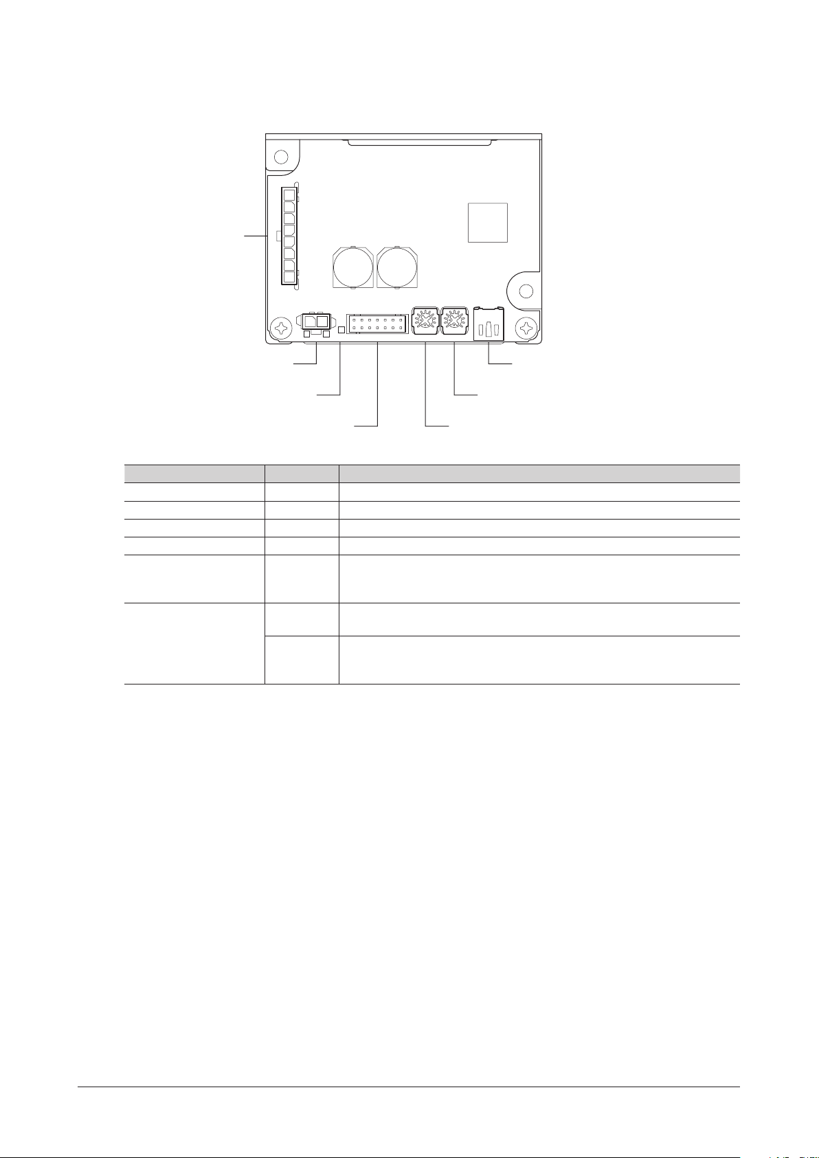
4.5 Names and functions of parts
This section explains the name and function for each part of the driver.
CN3
-
+
CN1 PWR/ALM VR2VR1 CN4CN2
Power supply connector (CN1)
USB connector (CN4)
LED (PWR/ALM)
Name Indication Description
Power supply connector CN1 Connects the power supply cable.
I/O signal connector CN2 Connects the I/O signal cable to connect with an external control device.
Motor connector CN3 Connects the motor cable.
USB connector CN4 Connects a PC in which the
MEXE02
has been installed.
Lit in green while the power is supplied.
LED PWR/ALM
If an alarm is generated, this LED will blink in red.
If information is generated, it will blink in orange.
Uses to set the operation data.
Factory setting: The rotation speed in the operation data No.1 can be set.
Uses to set the operation data.
Factory setting: The acceleration time and deceleration time in the operation
Internal potentiometer
VR1
*
VR2
data No.0 and No.1 can be set.
The function can be changed using the
*
MEXE02
.
6
Page 7
5 Installation
Horizontal direction:
:
:
Horizontal direction:
5.1 Installation location
The driver is designed and manufactured to be incorporated in equipment.
Install it in a well-ventilated location that provides easy access for inspection. The location must also satisfy the following
conditions:
•Inside an enclosure that is installed indoors (provide vent holes)
•Operating ambient temperature: 0 to +50°C [+32 to +122 °F] (non-freezing)
•Operating ambient humidity: 85% or less (non-condensing)
•Area that is free of explosive atmosphere or toxic gas (such as sulfuric gas) or liquid
•Area not exposed to direct sun
•Area free of excessive amount of dust, iron particles or the like
•Area free of excessive salt
•Area not subject to splashing water (rain, water droplets), oil (oil droplets) or other liquids
•Area not subject to continuous vibration or excessive shocks
•Area free of excessive electromagnetic noise (from welders, power machinery, etc.)
•Area free of radioactive materials, magnetic elds or vacuum
•Altitude: Up to 1000 m (3300 ft.) above sea level
Installation
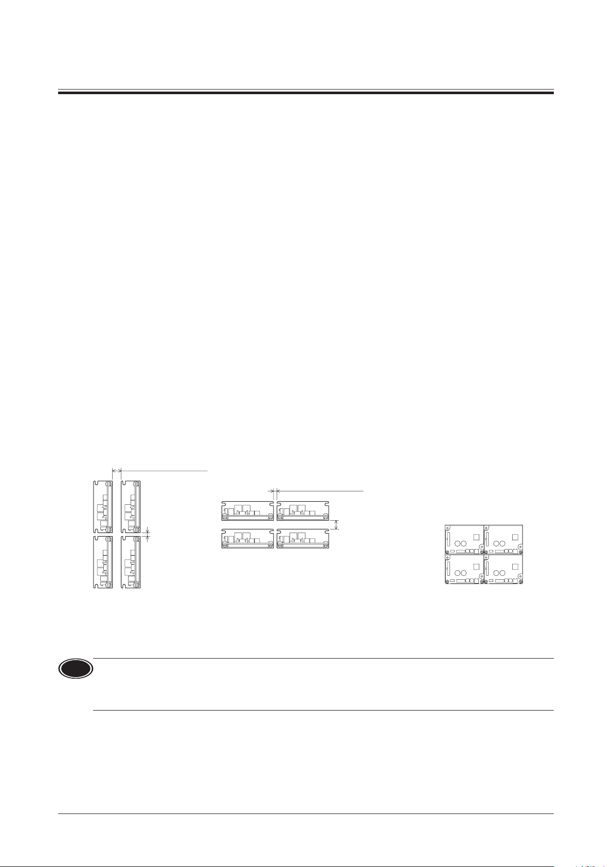
5.2 Installing the driver
Installation direction
The driver is designed on the basis of heat radiation by air convection and heat conduction to an enclosure.
When installing the driver in an enclosure, be sure to use the mounting holes on the driver, and install it in a vertical
direction or horizontal direction.
zVertical installation zHorizontal installation
50 mm (1.97 in.) or more
Vertical direction
20 mm (0.79 in.)
or more
Installation method
Install the driver onto an appropriate at metal plate having excellent vibration resistance and heat conductivity.
Using the mounting holes or notches of the driver, secure it with two screws (M3: not included) so as not to leave a gap
between the driver and metal plate.
20 mm (0.79 in.) or more
Vertical direction
50 mm (1.97 in.)
or more
•Drivers can be installed as shown in
the gure below.
When using the drivers via USB
communication, install them while
taking the cable leading position into
account.
Note
•Do not install any equipment that generates a large amount of heat or noise near the driver.
•If the ambient temperature of the driver exceeds the upper limit of the operating ambient temperature, reconsider
the ventilation condition or forcibly cool the area around the driver using a fan in order to keep within the operating
ambient temperature.
7
Page 8
Connection
6 Connection
This chapter explains how to connect the driver with the motor, power supply cable, and I/O signals.
6.1 Connecting the motor and driver (CN3)
Insert the motor cable connector into the motor connector (CN3) on the driver.
When extending the motor cable, use a connection cable (sold separately).
The maximum extension distance including the cable length of the motor itself should be 2 m (6.6 ft.).
Note
•Firmly insert the connector in position. Insecure connector connection may cause malfunction or damage to the
motor or driver.
•Be sure to insert and pull out the connector while holding the connectors part. Do not apply any force in a direction
other than the direction of inserting and pulling out the connector. Applying improper force may cause damage to
the connector and driver.
CN3 pin assignment
Pin No. Lead wire color *Lead wire size
1 Gray (Black)
2 Purple
3 Blue
4 Yellow
5 Green
6 Orange
7 Red
8 Brown (White)
The color in the parentheses ( ) indicates the 15 W type.
*
AWG22
(AWG24)
Viewed from the direction of an
*
arrow in the right gure
Housing: 43645-0800 (molex)
Terminal: 43030-0001 (molex)
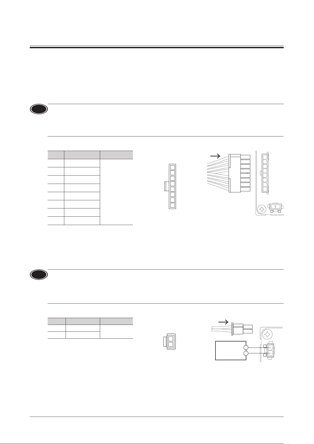
6.2 Connecting the power supply (CN1)
Insert the power supply cable connector into the power supply connector (CN1) on the driver.
Lead wire size: AWG22 (0.3 mm
2
)
1
2
3
4
5
6
7
8
CN3
-
+
CN1
Note
•When connecting, pay attention to the polarity of the power supply. Connection with incorrect polarity may cause
damage to the driver.
•Do not wire the power supply cable of the driver in the same cable duct with other power lines or motor cables.
•When turning on the power again or inserting/pulling out the motor cable connector, turn o the power and wait
for at least 5 seconds before doing so.
CN1 pin assignment
Pin No. Lead wire color Lead size
1 Red
2 Black
AWG22
Viewed from the direction of an
arrow in the right gure
1
2
Housing: 43645-0200 (molex)
Terminal: 43030-0001 (molex)
24 VDC±10%
+
-
−
+
CN1
8
Page 9
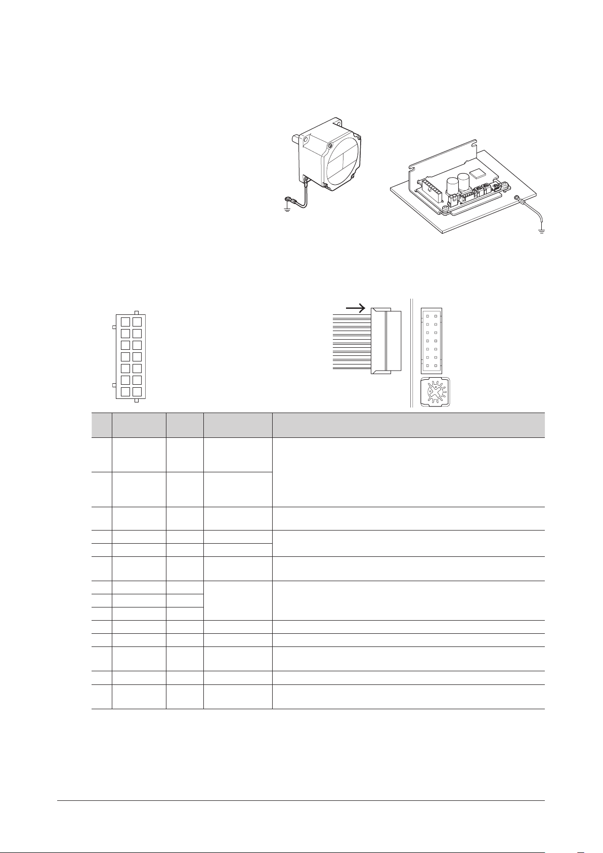
6.3 Grounding
The wire used to ground the motor and driver must be as thick and short to the grounding point as possible so that no
potential dierence is generated. Choose a large, thick and uniformly conductive surface for the grounding point.
zGrounding the motor
Connect the grounding wire along with a
set screw to the grounding point, using a
shakeproof washer.
For the 15 W type motor, remove the paint from
the mounting surface of the geared motor, and
install it to a metal surface that has grounded.
6.4 Connecting the I/O signals (CN2)
Insert the connector of the I/O signal cable into the I/O signal connector (CN2) of the driver.
Lead wire size: AWG26 (0.14 mm
CN2 pin assignment
Viewed from the direction of an arrow in the right gure
1413
1211
109
87
65
43
21
Housing: PHDR-14VS (JST)
Terminal: SPHD-001T-P0.5 (JST )
2
)
Connection
zGrounding the driver
Install the driver to a metal surface that
has grounded.
VR2CN2
Pin
Lead wire
No.
14 Yellow/Black DIN0 [START/STOP]
13
12 Red/White DIN2 [FWD/REV]
11 Brown/White DIN3 [M0]
10 Black DIN4 [M1]
9 White DIN5 [ALM-RST]
8 Gray VH
7 Purple VM
6 Blue VL
5 Green GND GND I/O signals common
4 Yellow DOUT0 [SPEED-OUT] 30 pulses are output while the motor output shaft makes one revolution.
3 Orange DOUT1 [ALM-B]
2 Red DOUT2 [TLC] This is a signal to output when the motor output torque is limited.
1 Brown DOUT3 [DIR]
*1
*2
*3
*4
color
Orange/
White
A signal assigned at the time of shipment is described in brackets [ ]. Functions for the pin No.1 to No.4 and No.9 to No.14
can be changed using the MEXE02.
The rotation direction of the output shaft varies depending on the gear ratio of the gearhead.
The rotation direction can be changed by setting of the "Motor rotation direction" parameter.
If the "External setting method" parameter is changed, the rotation speed and torque limiting value can be set with the
PWM signal input.
The torque limiting value is set to 200% at the time of shipment and can be changed using the MEXE02.
Terminal
name
Initial assignment
signal
DIN1 [RUN/BRAKE]
External analog
setting device
*1
These signals are used to operate the motor.
The motor rotates according to the acceleration time when both the
START/STOP input and the RUN/BRAKE input are turned ON.
If the START/STOP input is turned OFF, the motor stops according to the
deceleration time. If the RUN/BRAKE input is turned OFF, the motor stops
instantaneously.
This signal is used to change the motor rotation direction.
The motor rotates in the forward direction when the signal is turned ON.
The operation data number can be selected based on a combination of
ON-OFF status of the M0 and M1 inputs.
This signal is used to reset the alarm.
(The alarm will be reset at the ON edge of the input.)
These terminals are used when the rotation speed or torque limiting
value is externally set using an external analog setting device (external
*3
potentiometer or external DC voltage).
This is a signal to output an alarm status.
It is turned OFF when an alarm is generated. (Normally closed)
This is a signal to output information of the motor rotation direction.
(It is turned ON when the motor rotates in the forward direction.)
Description
*2
*4
9
Page 10

Connection
Driver internal circuit
4.5 to 26.4 VDC
1, 2, 3,
wheel diode
6.5 Driver I/O circuit
Input signals circuit
Input signals of the driver are C-MOS inputs.
The signal state represents "ON: 0 to 0.5 V (L level)"
and "OFF: 4 to 5 V (H level)."
+5 V
zChanging the logic level setting of input signals
The logic level setting for input terminals DIN0 to DIN5 can be changed using the
Refer to the USER MANUAL for details.
Output signals circuit
Output signals of the driver are transistor open-collector
outputs. The signal state represents a state of "ON:
Carrying current" or "OFF: Not carrying current" for the
internal photocoupler rather than the voltage level of
the signal.
R∗
9, 10, 11,
12, 13, 14
MEXE02
0 V
Pin No.
GND
Pin No.
1, 2, 3, 4
5
GND
10 kΩ
C-MOS
R
C
0 V
.
Driver internal circuit
5
0 V
Recommended resistance value when a current limiting resistor
*
R is connected:
For 24 VDC: 2.7 kΩ to 4.7 kΩ (1 W)
For 5 VDC: 560 Ω to 820 Ω (0.25 W)
zChanging the logic level setting of output signals
The logic level setting for output terminals DOUT0 to DOUT3 can be changed using the
However, if the SPEED-OUT output is assigned, it cannot be changed.
Refer to the USER MANUAL for details.
Note
•Be sure to suppress a current owing to the output circuit at 10 mA or less.
Connect a current limiting resistor R externally if the current exceeds this specied value.
•When a relay (inductive load) is connected, provide a control measure for
the y-back voltage against the relay by connecting a diode. Or use a relay
with built-in ywheel diode.
MEXE02
Pin No.
.
Inductive load
Fly
4
10
Page 11

6.6 Connecting external analog setting devices
External potentiometer
r
I/O signal connector
I/O signal connector
Using an external potentiometer (sold separately), external DC voltage, or PWM signal input, the rotation speed or
torque limiting value can be set.
Using an external potentiometer
Connect to the pin No.6 to No.8 of the CN2.
PAVR2-20K
(sold separately)
0 to 20 kΩ
3
21
Connection
I/O signal connecto
(CN2)
Gray
8
VH
Purple
Blue
VM
7
6
VL
Note
Note
When a shielded cable is used for connection with the external potentiometer, connect shields to VL of the pin No.6
from near the I/O signal connector (CN2).
Using external DC voltage
For the external voltage, use a DC power supply (0 to 5 VDC) with
reinforced insulation on its primary and secondary sides, and
connect to the pin No.6 and No.7 of the CN2.
Input impedance between the VM input and VL input is
approximately 47 kΩ.
The VL input is connected to GND inside the driver.
•Be sure to use the voltage of an external control device at 5 VDC or lower.
When connecting an external control device, make sure the polarities are correct. If the polarities are reversed, the
driver may be damaged.
•When a shielded cable is used for connection with the external control device, connect shields to VL of the pin No.6
from near the I/O signal connector (CN2).
Using PWM signal input
When the operation data is set using the PWM signal input, connect
the PWM signal lines to the pin No.6 and No.7 of the CN2.
Refer to the USER MANUAL for details about the PWM signal.
External DC
power supply
0 to 5 VDC
1 mA or more
PWM signal
(CN2)
+
–
+
–
Purple
Blue
Purple
Blue
7
6
(CN2)
7
6
VM
VL
VM
VL
6.7 Connecting the USB cable (CN4)
Note
Connect the USB cable to the USB connector when
using the
MEXE02
•Connect the driver and PC directly with the USB cable without using a hub or extension cable.
•In large electrically noisy environments, use the USB cable with a ferrite core or install a ferrite core to the USB cable.
.
Specications of USB cable
Specications USB2.0 (full speed)
Cable
Length: 3 m (9.8 ft.) or less
Shape: A to mini B
11
Page 12

Connection
Driver
Grounding
Grounding
T
control devic
6.8 Connection diagram
The gure shows an example when an external potentiometer is connected.
+
–
VH
VM
VL
GND
CN1
+
–
CN2
14
13
12
11
10
9
8
7
6
5
4
3
2
1
Motor connector
CN3
DC power supply
24 VDC±10%
Connecting input signals
DIN0 (START/STOP)
DIN1 (RUN/BRAKE)
External potentiometer
PAVR2-20K
(sold separately)
o external
p.10
0 to 20 kΩ
3
21
Connecting output signals
e
DIN2 (FWD/REV)
DIN3 (M0)
DIN4 (M1)
DIN5 (ALM-RST)
DOUT0 (SPEED-OUT)
DOUT1 (ALM-B)
DOUT2 (TLC)
DOUT3 (DIR)
Connecting the motor
Motor
CN4
Connecting the USB
Note
Insulate unused lead wires which are on the opposite side to the connector of the I/O signal cable to prevent them
from contacting other devices, or connect them to 5 VDC or the signal ground (GND) of your external control device
according to usage of signals.
12
Page 13

6.9 Noise measures
Cable cramp
Shielded cable
There are two types of electrical noises: One is a noise to invade into the driver from the outside and cause the driver
malfunction, and the other is a noise to emit from the driver and cause peripheral equipments malfunction.
For the noise that is invaded from the outside, take measures to prevent the driver malfunction. It is needed to take
adequate measures because signal lines are very likely to be aected by the noise.
For the noise that is emitted from the driver, take measures to suppress it.
Measures against electrical noise
There are the following three methods mainly to take measures against the electrical noise.
zNoise suppression
•When relays or electromagnetic switches are used, use noise lters or CR circuits to suppress surge generated by
them.
•Use a connection cable (sold separately) when extending the wiring distance between the motor and the driver.
This is eective in suppressing the electrical noise emitted from the motor.
•Cover the driver by a metal plate such as aluminum. This is eective in shielding the electrical noise emitted from the
driver.
zPrevention of noise propagation
•Separate power lines such as motor cable and power supply cable from signal lines for a distance of 100 mm (3.94 in.)
or more, and also do not bundle them or wire them in parallel. If the power lines must cross over the signal lines, wire
them at right angles.
•Use a cable of AWG26 (0.14 mm
or less.
•For more eective elimination of noise, use shielded cables for a power supply cable and I/O signal cable, or attach
ferrite cores if non-shielded cables are used.
•Keep cables as short as possible without coiling and bundling extra lengths.
•To ground a shielded cable, use a metal cable clamp that can
maintain contact with the entire circumference of the shielded
cable, and ground as near the product as possible.
Connection
2
) or thicker for the signal cable of the driver, and keep the wiring distance of 3 m (9.8ft.)
•Grounding multiple points will increase eect to block electrical noise because impedance on the grounding points is
decreased.
However, ground them so that a potential dierence does not occur among the grounding points.
zSuppression of eect by noise propagation
•Loop the noise propagated cable around a ferrite core. Doing so will prevent the propagated noise invades into the
driver or emits from the driver. The frequency band in which an eect by the ferrite core can be seen is generally
1 MHz or more. Check the frequency characteristics of the ferrite core used. When increasing the eect of noise
attenuation by the ferrite core, loop the cable a lot.
6.10 Conformity to the EMC Directive
Eective measures must be taken against the EMI that the motor and driver may give to adjacent control-system
equipment, as well as the EMS of the motor and driver itself, in order to prevent a serious functional impediment in the
machinery. The use of the following installation and wiring methods will enable the motor and driver to be compliant
with the EMC directive. Refer to p.27 for the applicable standards.
Oriental Motor conducts EMC measurements on its motors and drivers in accordance with "Example of installation and
wiring" shown on the next page.
The user is responsible for ensuring the machine’s compliance with the EMC Directive, based on the installation and
wiring explained below.
About power supply
The
optimally conforms to the EMC Directive.
Connecting the motor cable
When extending the motor cable, use a connection cable (sold separately). The maximum extension distance including
the cable length of the motor itself should be 2 m (6.6 ft.).
Series is a product of DC power supply input. Use a DC power supply (such as a switching power supply) that
BLH
13
Page 14

Connection
Motor
potentiometer
Ferrite core
Use a ferrite core to suppress eect by noise propagation.
Use 7427122 (Würth Elektronik GmbH & Co.KG), ZCAT3035-1330 (TDK Corporation) or equivalent ferrite cores.
Install the ferrite core as close as possible to the driver.
Wiring the I/O signal cable
Refer to "Prevention of noise propagation" on p.13.
Notes about installation and wiring
•Connect the motor, driver and other peripheral control equipment directly to the grounding point so as to prevent a
potential dierence from developing between grounds.
•When relays or electromagnetic switches are used together with the system, use noise lters and CR circuits to
suppress surges generated by them.
•Keep a power supply cable and signal cable as short as possible without coiling and bundling extra lengths.
•Separate power lines such as motor cable and power supply cable from signal lines, and wire them apart as much
as possible [example: about 100 to 200 mm (3.94 to 7.87 in.)]. If the power lines must cross over the signal lines, wire
them at right angles.
Example of installation and wiring
Driver
Motor cable
DC power supply
Precautions about static electricity
Static electricity may cause the driver to malfunction or suer damage. Be careful when handling the driver while the
power is supplied.
Always use an insulated screwdriver to adjust the internal potentiometers of the driver.
Note
Do not approach or touch the driver while the power is supplied.
Ferrite core
Power supply cable
[2 m (6.6 ft.) or less]
(Grounded panel)
I/O signal cable
[3 m (9.8 ft.) or less]
External potentiometer cable
[3 m (9.8 ft.) or less]
External
14
Page 15

6.11 I/O signals list
This section explains about input signals and output signals.
Input signals
Terminal name Signal name Description
DIN0 START/STOP This signal is used to rotate the motor or decelerate to stop it.
DIN2 FWD/REV This signal is used to select the motor rotation direction.
DIN3 M0
DIN4 M1
DIN5 ALM-RST This signal is used to reset the alarm generated presently.
Signals
possible to
change the
assignment
This is a signal to switch using a parameter.
*
Output signals
Terminal name Signal name Description
DOUT0 SPEED-OUT
DOUT1 ALM-B If an alarm is generated, this output is turned OFF (normally closed).
DOUT2 TLC When the output torque is limited, this output is turned ON.
DOUT3 DIR
Signals
possible to
change the
assignment
STOP-MODE
INFO-DRVTMP
INFO-OVOLT
INFO-UVOLT
INFO-LOAD
INFO-TRQ-DE
INFO-SPD-DE
INFO-PTIME
INFO-PCOUNT
INFO-DSLMTD
INFO-IOTEST
3-Wire modeDIN1 RUN/BRAKE This signal is used to rotate the motor or stop it instantaneously.
These signal are used to select the operation data number.
FWD
*
*
M2 This signal is used to select the operation data number.
TL This signal is used to switch whether to enable or disable the torque limiting function.
INFO-CLR This signal is used to reset the information generated presently.
HMI This signal is used to release the function limitation of the
EXT-ERROR This signal is used to stop the motor forcibly by the external signal.
ALM-A If an alarm is generated, this output is turned ON (normally open).
MOVE When the motor rotates, this output is turned ON.
INFO Information status of the driver is output.
VA
INFO-SPD
INFO-SET-E
INFO-DRV
INFO-TRIP
INFO-ODO
INFO-CFG
INFO-RBT
This signal is used to rotate the motor in the forward direction.
This signal is used to rotate the motor in the reverse direction.
This signal is used to select how to stop the motor.
*
MEXE02
30 pulses are output while the motor output shaft makes one revolution in
synchronization with the motor rotation.
Information of the motor rotation direction is output. (When the motor rotates in the
forward direction: ON)
The ON state will be continued until the motor will reversely rotates.
When the detected speed reached the plus or minus range of "VA detection width"
with respect to the setting speed, this output is turned ON.
When the corresponding information is generated, the output is turned ON.
.
2-Wire modeREV
Connection
: These signals are assigned at the time of shipment.
Refer to the USER MANUAL when changing the signal assigned to the I/O signal terminals.
15
Page 16

Operation
Motor
External potentiometer
r
PAVR2-20K
Motor output shaft speed [r/min]
PAVR2-20K [scale]
External potentiometer -
HIGH
7 Operation
This chapter explains how to operate the product in a state of the factory setting without using the
7.1 Guidance
DC power supply
24 VDC
External control
equipment
Driver
Setting the acceleration time
and deceleration time
Operation
and stop
.
, settings of
MEXE02
Using the
MEXE02
MEXE02
the operation data and functions
VR1VR2
of the product can be extended.
Refer to the USER MANUAL for
details.
Setting the rotation speed
0 to 5 VDC
External
potentiometer
External
DC voltage
VR1
7.2 Setting the rotation speed
The rotation speed can be set using the external analog setting device (external potentiometer or external DC voltage)
or VR1.
Whether to use the external analog setting device or VR1 can be selected by switching the ON/OFF status of the M0
input.
The setting range is 100 to 3000 r/min.
The setting range of the
M0 input OFF ON
Speed setting
External potentiometer
An external potentiometer is used when the speed is set from a place away from the driver.
Use the
PAVR2-20K
PAVR2-20K
(sold separately)
0 to 20 kΩ
3
21
MEXE02
External analog
setting device
(sold separately) for an external potentiometer.
is 80 to 3150 r/min. Refer to the USER MANUAL for details.
VR1
I/O signal connecto
(CN2)
Gray
8
VH
Purple
Blue
VM
7
6
VL
LOW
HIGH
Rotation speed characteristics
(representative values)
3000
2500
2000
1500
1000
500
LOW
16
Page 17

External DC voltage
External DC voltage -
Motor output shaft speed [r/min]
012345
Setting voltage [VDC]
I/O signal connector
Internal potentiometer -
Motor output shaft speed[r/min]
VR1 [scale]
HIGH
VR1
HIGH
Acceleration/deceleration time [s]
HIGH
Internal potentiometer - Acceleration/
[scale]
VR2
LOW
External DC voltage is used when the speed is set from an external
control device.
For the external DC voltage, use a DC power supply (0 to 5 VDC, 1 mA or
more) with reinforced insulation on its primary and secondary sides.
External DC
power supply
0 to 5 VDC
1 mA or more
VR1
+
–
Purple
Blue
(CN2)
7
6
VM
VL
The internal potentiometer VR1 is used when the rotation speed is
not changed frequently or is set without providing an external setting
device.
Adjust the potentiometer using an insulated screwdriver.
Factory setting: 0 r/min
LOW
Operation
Rotation speed characteristics
(representative values)
3000
2500
2000
1500
1000
500
Rotation speed characteristics
(representative values)
3000
2500
2000
1500
1000
500
7.3 Setting the acceleration time and deceleration time
The acceleration time and deceleration time can be set so that an impact
is not applied to a load when the motor starts or stops.
The acceleration time refers to a time needed for the motor to reach
3000 r/min from a standstill state.
The deceleration time refers to a time needed for the motor to stop from
the 3000 r/min.
The actual acceleration time and deceleration time vary depending
on the conditions of use, load inertia, or load torque specied by the
customer.
The setting range is 0.1 s to 15.0 s.
Factory setting: 0.1 s
HIGH
LOW
deceleration time characteristics
(representative values)
16
14
12
10
8
6
4
2
0
LOW
VR2
17
Page 18

Operation
Switching between two speed levels,
START/STOP
input
FWD/REV
input
RUN/BRAKE
input
M0 input
OFF
SPEED-OUT
output
7.4 Operation and stop
To switch between operation and stop movement (instantaneous stop or deceleration stop) of the motor in the 3-wire
mode, the START/STOP input and RUN/BRAKE input are used.
START/STOP input RUN/BRAKE input Motor operation
ON ON Operation
Signal level
If the RUN/BRAKE input is turned OFF during deceleration stop, the motor stops instantaneously.
Deceleration stop: The motor decelerates to a stop according to a time set in the deceleration time.
Instantaneous stop: The motor stops at the shortest time without following the deceleration time.
ON OFF Instantaneous stop
OFF ON Deceleration stop
Note
•When the START/STOP input and the RUN/BRAKE input are turned OFF simultaneously, the RUN/BRAKE input is
prioritized.
•The actual acceleration time and deceleration time are aected by customer's conditions of use, load inertia, and
load torque.
Examples of operation patterns
The gure shows an example of the 3-wire mode when 2000 r/min is set in the operation data No.0 and 650 r/min is set
in the operating data No.1.
The rotation direction show the round shaft type. It varies depending on the gear ratio of gearhead.
Deceleration stop
Motor operation
CW CW CW CW
2000 r/min
650 r/min
Run, Instantaneous stopRotation direction switching
CCW
Note
18
ON
OFF
ON
OFF
ON
∗
*
OFF
ON
OFF
ON
The motor rotation direction when the FWD/REV input is turned ON can be changed by setting of the "Motor rotation
direction" parameter. Refer to the USER MANUAL for details.
START
RUN
FWD
No.0 No.1 No.1No.0 No.0
START
RUNRUN
REV
To surely recognize the input signal, ensure the ON time and OFF time of each input signal for at least 10 ms.
FWD
Page 19

7.5 Rotation direction of the motor output shaft
(CW)
REV input signal
The rotation direction of the motor output shaft represents the direction when
viewed from the motor output shaft.
The motor rotation direction can be changed using the
The gure shows when the "Motor rotation direction" parameter is set to "+=CW."
MEXE02
Rotation direction of the gearhead output shaft
The rotation direction of the gearhead output shaft varies depending on the type or the gear ratio of the gearhead.
Check the operating manual supplied with the motor for the rotation direction of the gearhead output shaft.
.
Operation
(CCW)
FWD input signal
19
Page 20

Operation
3
VRx
Power line
Speed setting line
7.6 Multi-motor control
Operating two or more motors at the same speed can be performed using any of the external potentiometer, external
DC voltage, or PWM signal.
Using an external potentiometer
Use common lines for the power supply and speed setting, and set the speed using VRx as shown in the gure below.
•Obtain the resistance value for the external speed potentiometer as follows.
Resistance VRx when the number of drivers is n units: VRx (kΩ) = 20 kΩ/n, permissible dissipation (W) = n/20
Example: If two drivers are connected, 10 kΩ and 1/10 W are obtained.
•For I/O signals other than the speed setting, connect for each driver.
•If multiple motors are used with speed dierences among them, adjust as follows.
The rst driver: Connect a resistor of 1.5 kΩ, 1/20 W to the terminal M on the driver.
The second and subsequent drivers: Connect a variable resistor (VRn) of 5 kΩ, 1/20 W to the terminal M on the driver.
•Keep the number of drivers to 10 units or less in multi-motor control using an external potentiometer.
2
1
Driver
CN2
CN1
VH
VM
VL
+24 V
GND
1.5 kΩ, 1/20 W
Speed setting line
CN2
CN1
Driver
+24 V
GND
VH
VM
VL
VRn
5 kΩ, 1/20 W
Using external DC voltage
•Use a DC power supply whose current capacity is at least the value calculated by the formula below.
Current capacity (mA) when the number of drivers is n units = 1mA × n
Example: If two drivers are connected, the current capacity should be at least 2 mA.
•For I/O signals other than the speed setting, connect for each driver.
•If multiple motors are used with speed dierences among them, adjust as follows.
The rst driver: Connect a resistor of 1.5 kΩ, 1/20 W to the terminal M on the driver.
The second and subsequent drivers: Connect a variable resistor (VRn) of 5 kΩ, 1/20 W to the terminal M on the driver.
DC power supply
0 to 5 VDC
Power line
+
–
CN2
CN1
Driver
VH
VM
VL
+24 V
GND
1.5 kΩ, 1/20 W
CN2
CN1
Driver
+24 V
GND
VH
VM
VL
VRn
5 kΩ, 1/20 W
20
Page 21

8 Maintenance and inspection
8.1 Inspection
It is recommended that periodic inspections would be conducted for the items listed below after each operation of the
motor.
If an abnormal condition is noted, discontinue any use and contact your nearest Oriental Motor sales oce.
Maintenance and inspection
Note
•Do not conduct the insulation resistance measurement or dielectric strength test with the motor and driver
connected.
Doing so may cause damage to the product.
•The driver uses semiconductor elements, so be extremely careful when handling them.
Static electricity may damage the driver.
Inspection item
•Check if any of the mounting screws of the motor and gearhead is loose.
•Check if the bearing part (ball bearings) of the motor generates unusual noises.
•Check if the bearing part (ball bearings) or gear meshing part of the gearhead generates unusual noises.
•Check if the output shaft of the motor and gearhead and a load shaft are out of alignment.
•Check if a damage or stress is applied on the cable or the connection part between the cable and driver is loose.
•Check if dust is deposited on the driver.
8.2 Warranty
Check on the Oriental Motor Website for the product warranty.
8.3 Disposal
Dispose the product correctly in accordance with laws and regulations, or instructions of local governments.
21
Page 22

Troubleshooting
9 Troubleshooting
The motor or driver may not operate properly if the rotation speed is wrongly set or the connection is wrong.
If the motor cannot operate properly, refer to the contents provided in this chapter and take appropriate action.
If the problem persists, contact your nearest Oriental Motor sales oce.
Note
Check the alarm contents when an alarm is generated.
I/O signal status can be checked using the monitor mode of the
I/O signals. Refer to the USER MANUAL for details.
●
The power supply is not connected correctly or it is improper connection.
Check the connection of the power supply.
▷
●
The operation input signal is not turned ON.
Check the connection and the ON-OFF status of signal.
▷
The signal input status can be checked using the internal I/O monitor or D-I/O monitor.
●
The operation data number is selected wrongly. Or the motor connector is not
connected properly.
Check the connection and the ON-OFF status of signal.
▷
The motor does not rotate.
The signal input status can be checked using the internal I/O monitor or D-I/O monitor.
●
An alarm is present.
Check if an alarm is generated.
▷
The PWR/ALM LED blinks in red while an alarm is present.
The alarm content can be checked by counting the number of times the LED blinks or
by using the
Refer to p.24, and reset the alarm after removing the cause of the alarm.
●
The operation data is set wrongly.
Check how to set the operation data.
▷
The setting method and setting value of the operation data selected can be checked
using the status monitor.
●
The operation data number is selected wrongly. Or the motor connector is not
MEXE02
.
connected properly.
Check the connection and the ON-OFF status of signal.
▷
The signal input status can be checked using the internal I/O monitor or D-I/O monitor.
●
The setting method or setting value is wrong.
Check the setting method.
The motor does not move
according to the set
operation data.
▷
The setting method and setting value presently selected can be checked using the
status monitor.
●
A load is too large.
Check if the torque is enough.
▷
●
An external analog setting device or PWM signal input is set wrongly.
Check the setting value of the "External setting method" parameter.
▷
The setting of the "External setting method" parameter can be checked using the unit
information monitor.
MEXE02
. Use it to check the wiring condition of the
22
The rotation speed cannot
be increased.
The rotation speed cannot
be decreased.
• A time for stopping is long.
• The stopping method is
wrong.
●
The rotation speed equal to or higher than the value set in the "Speed upper
limit" parameter is set.
Reconsider the setting value of the "Speed upper limit" parameter or operation data.
▷
●
The rotation speed lower than the value set in the "Speed lower limit" parameter
is set.
Reconsider the setting value of the "Speed lower limit" parameter or operation data.
▷
●
The stopping method is wrongly selected.
Check the stopping method. In the case of the 3-wire mode of the operation input
▷
mode, the stop movement by turning the RUN/BRAKE input OFF is dierent from that by
turning the START/STOP input OFF.
In the case of the 2-wire mode of the operation input mode, the stop movement when
the STOP-MODE input is ON is dierent from that when it is OFF. Refer to the USER
MANUAL for details.
For the deceleration stop, check the setting value of the "Deceleration mode selection"
▷
parameter.
Check the setting value of the parameter using the unit information monitor.
●
Load inertia is too large.
Check by increasing the frictional load or reducing the load inertia.
▷
Page 23

Torque limiting value is not
increased.
Torque cannot be limited.
The PWR/ALM LED blinks in
orange.
The motor rotates in the
opposite direction to the
specied one.
Troubleshooting
●
The value set in the "Torque limiting maximum value" parameter is exceeded.
Reconsider the setting value of the "Torque limiting maximum value" parameter or
▷
operation data.
●
If the TL input is turned OFF, the torque limiting function is disabled.
Check the connection and the ON-OFF status of signal.
▷
The signal input status can be checked using the internal I/O monitor or D-I/O monitor.
●
Information is present.
Information is present because of any of the causes.
▷
Check the generated information using the information monitor or internal I/O monitor,
and clear the cause of generation or disable the "INFO action" parameter.
●
The ON-OFF operation of the FWD/REV input is used wrongly or the FWD/REV
input is not connected correctly.
Check the connection and the ON-OFF status of signal.
▷
The signal input status can be checked using the internal I/O monitor or D-I/O monitor.
●
The setting of the "Motor rotation direction" parameter has been changed.
The motor rotates in the forward direction when the FWD/REV input is turned ON.
▷
The setting for rotating in the forward direction can be set with the "Motor rotation
direction" parameter.
(Initial value: +=CW)
●
The gearhead with a reduction ratio which rotation direction is opposite to the
motor output shaft is used. (Refer to p.19 for the rotation direction of the gearhead
output shaft)
Reverse the ON-OFF status of the FWD/REV input or invert the logic level setting of the
▷
input.
Change the setting for the "Motor rotation direction" parameter.
●
A hollow shaft at gearhead is used.
The hollow shaft at gearhead rotates in the opposite direction to the motor when
▷
viewed from the front side of the gearhead, and rotates in the same direction to the
motor when viewed from the rear side (motor mounting side).
• The motor movement is not
stable.
• Motor vibration is too large.
●
The motor and gearhead output shaft and a load shaft are out of alignment.
Check the coupling condition of the motor and gearhead output shaft and the load
▷
shaft.
●
The motor output power and the driver output power are not matched.
Check if the motor output power and the driver output power are the same.
▷
The driver output power can be checked by the driver model name in the unit
information monitor.
●
The product is aected by electrical noise.
Check the operation using the motor, driver and a minimum of external equipment
▷
required for operation.
If an eect of noise has been conrmed, implement the following countermeasures:
[Keep away from the noise sources.] [Reconsider the wiring.]
23
Page 24

Alarms
Blinking state
of LED
[Example: When LED blinks three times (sensor error)]
0.3 s
0.3 s
ALM-A output
ALM-RST input
START/STOP input
RUN/BRAKE input
Mot
ALM-B output
OFF
10 Alarms
This driver has the alarm function to protect from temperature rise, poor connection, error in operation, and others. If an
alarm is generated, the ALM-A output is turned ON (in the case of normally open), or the ALM-B output is turned OFF (in
the case of normally closed). At the same time, the motor stops, and the PWR/ALM LED blinks in red.
The generated alarm content can be checked by counting the number of times the LED blinks or by using the
Refer to the USER MANUAL for details.
1.5 s
MEXE02
.
10.1 Alarm reset
Before resetting an alarm by one of the following methods, be sure to remove the cause of the alarm and ensure safety.
•Turn the ALM-RST input ON. (The alarm will be reset at the ON edge of the input.)
•Turn on the power again.
•Execute the alarm reset using the
Note
•Some alarms cannot be reset other than turning on the power again.
Refer to "10.3 Alarm lists" on the next page.
•Continuing the operation without removing the cause of the alarm may cause damage to equipment.
•Operation cannot be performed until the alarm is reset.
•Perform the ALARM-RESET input after the motor (gearhead) output shaft is stopped completely.
Turn the operation input signal OFF, and remove the cause of the alarm before resetting the alarm.
The alarm reset is disabled while the operation input signal is being ON.
or movement
Lit
Unlit
Alarm generation
CW CW
Lit
MEXE02
∗
Stop
.
Lit
Lit
Lit
Lit
10.2 Alarm history
24
ON
OFF
10 ms or more
ON
OFF
ON
OFF
10 ms or less
ON
If an alarm is generated while the motor rotates, the motor will coast to a stop.
*
Up to 10 generated alarms are saved in the non-volatile memory in order of the latest to oldest.
Exceeding 10 alarm records will overwrite the data in order from the oldest recorded data.
Alarm history is not cleared even if the power is shut o.
The alarm history and the driver status when an alarm is generated can be checked using the
Refer to the USER MANUAL for details.
MEXE02
.
Page 25

10.3 Alarm lists
Alarms
Number of times
PWR/ALM LED
blinks
Two times Overload
Three times
Four times Overvoltage
Five times Undervoltage
Six times Overspeed
Seven times Overcurrent
Eight times EEPROM error
Nine times
10 times External stop
11 times
Lit CPU error
The setting can be changed using the "Overload alarm detection time" parameter. Refer to the USER MANUAL for details.
*
Alarm name Cause Remedial action
•Decrease a load.
•Reconsider operating conditions such as
the acceleration time and deceleration
time.
•If the alarm is generated at a low
temperature, warm up.
Check the connection between the driver
and motor.
•Check the power supply voltage.
•If the alarm is generated during
operation, decrease a load or increase
the deceleration time.
•If the motor is rotated by external force,
reconsider how to use or environment.
•Check the power supply voltage.
•Check the wiring of the power supply
cable.
•Decrease a load.
•Reconsider operating conditions such as
the acceleration time and deceleration
time.
•If the motor is rotated by external force,
reconsider how to use or environment.
Turn o the power, and turn on the power
again after checking if the product is not
damaged.
If the alarm is not cleared, contact your
nearest Oriental Motor sales oce.
Initialize the parameters, and turn on the
power again.
•Reconsider the ambient temperature.
•Reconsider the ventilation condition.
•Reconsider the operating condition.
Check the EXT-ERROR input signal.
Before supplying power to the driver, turn
the operation input signal OFF.
Turn on the power again.
If the alarm is not cleared, contact your
nearest Oriental Motor sales oce.
Sensor error
Sensor error
at power-on
Main circuit
overheat
Prevention of
operation at
power-on
A load exceeding the rated
torque was applied to the
motor for a time set in the
"Overload alarm detection time"
parameter or more.
The sensor line in the motor
cable was disconnected. Or the
motor cable was come o.
The sensor line in the motor
cable was disconnected. Or the
driver power supply was turned
on in a state where the motor
cable was come o.
•The internal voltage of the
driver exceeded 38 VDC.
•A large inertial load was
suddenly stopped.
The internal voltage of the
driver dropped below 18 VDC.
The motor rotation speed was
exceeded 5200 r/min.
Excessive current was own
through the driver due to
ground fault, etc.
The data stored in the driver
was damaged.
The internal temperature of the
driver exceeded 85 °C (185 °F).
•The EXT-ERROR input signal
was turned OFF.
•External stop was executed
using the
The power supply was turned
on in a state where the
"Prevention of operation at
power-on alarm" parameter
was set to "enable" and the
operation input signal was
being ON.
The CPU is not operated
properly.
MEXE02
*
.
Reset using
the ALM-RST
Not possible
Not possible
input
Possible
Possible
25
Page 26

Specications
e
55 (2.17) max.
72 (2.83) max.
11 Specications
11.1 Specications
Values in the rated torque, peak torque, rated rotation speed, and speed control range represent those in a state where
the gearhead is not combined. Refer to "4.4 Products possible to combine" (p.5) for the motor model name.
Model
Rated output power (Continuous) 15 W 30 W 50 W
Power
supply
input
Rated torque 0.048 N·m (6.8 oz-in) 0.115 N·m (16.3 oz-in) 0.191 N·m (27 oz-in)
Peak torque 0.072 N·m (10.2 oz-in) 0.173 N·m (24 oz-in) 0.287 N·m (40 oz-in)
Rated rotation speed 3000 r/min 2500 r/min
Speed control range (80 *) 100 to 3000 r/min
Digital setting
*
Motor
Driver
Rated voltage 24 VDC
Permissible voltage range
Rated input current 0.93 A 1.9 A 2.9 A
Maximum input current 2.3 A 4.1 A 5.4 A
Check on the Oriental Motor Website for the product specications.
11.2 General specications
Ambient temperature Driver: 0 to +50 °C [+32 to +122 °F] (non-freezing)
Ambient humidity 85% or less (non-condensing)
Altitude Up to 1000 m (3300 ft.) above sea level
Surrounding atmosphere
Operating environment
Vibration
Ambient temperature Driver:
Ambient humidity 85% or less (non-condensing)
Storage environment
Shipping environment
Degree of protection IP00
Altitude Up to 3000 m (10000 ft.) above sea level
Surrounding atmosphere
BLHM015K-
BLH2D15-KD BLH2D30-KD BLH2D50-KD
oo
No corrosive gas, dust, water or oil.
Cannot be used in radioactive materials, magnetic eld, vacuum or other
special environment.
(For details about installation locations, refer to p.7.)
Not subject to continuous vibrations or excessive impact.
In conformance with JIS C 60068-2-6 "Sine-wave vibration test method"
Frequency range: 10 to 55 Hz
Pulsating amplitude: 0.15 mm (0.006 in.)
Sweep direction: 3 directions (X, Y, Z)
Number of sweeps: 20 times
-
25 to +70 °C [-13 to +158 °F] (non-freezing)
No corrosive gas, dust, water or oil.
Cannot be used in radioactive materials, magnetic eld, vacuum or other
special environment.
BLHM230K-
-
10 to +10%
oo
BLHM450K-
oo
11.3 Dimension
Mass: 46 g (1.62 oz.) [Unit: mm (in.)]
26
4 (0.157)63±0.2 (2.480±0.008)
6 (0.236)
34.5±0.2
(1.358±0.008)
64±0.2 (2.520±0.008)
22±0.2
0.866
3.5 (0.138)
±0.008
( )
[50 (1.97)]
2×ϕ3.5 (ϕ0.138) Thru
3.5 (0.138)
Installation of motor cabl
Page 27

12 Regulations and standards
12.1 UL Standards and CSA Standards
This product is recognized by UL under the UL and CSA standards.
Applicable Standards Certication Body/Standards File No.
UL 62368-1
CSA C22.2 No.62368-1
12.2 EU Directives
CE Marking
This product is axed the CE Marking under the EMC Directive.
zLow Voltage Directives
•This product is not subject to the coverage of the Low Voltage Directive because the input power supply voltage is
24VDC.
•When conforming the equipment incorporating this product to the Low Voltage Directive, connect the driver power
supply input to the DC power supply where the primary and secondary sides are provided with reinforced insulation.
•Install this product inside an enclosure because it is designed and manufactured to be incorporated in equipment.
•Degree of protection for driver: IP00
UL/E208200
Regulations and standards
zEMC Directive
This product has received EMC compliance under the conditions specied in "Example of installation and wiring" on p.14.
The nal level of conformance of your mechanical equipment to the EMC Directive will vary depending on such factors
as the control system equipment used with the motor and driver, conguration of electrical parts, wiring, layout, and
hazard level. It therefore must be veried through conducting EMC measures on your mechanical equipment.
Applicable standards
EN 55011 group1 classA
EMI
EN 61000-6-4
EMS EN 61000-6-2
Caution This equipment is not intended for use in residential environments nor for use on a low-voltage public network
supplied in residential premises, and it may not provide adequate protection to radio reception interference in
such environments.
12.3 Republic of Korea, Radio Waves Act
KC Mark is axed to this product under the Radio Waves Act, the republic of Korea.
12.4 RoHS Directive
The products do not contain the substances exceeding the restriction values of RoHS Directive (2011/65/EU).
27
Page 28

•Unauthorized reproduction or copying of all or part of this manual is prohibited.
• Please contact your nearest Oriental Motor oce for further information.
T
8:30
7:30
www
Schiessstraße 44, 40549 Düsseldor
T
www
T
www
T
www
T
www.orientalmotor.it
o
T
www
If a new copy is required to replace an original manual that has been damaged or lost, please contact your nearest Oriental Motor
branch or sales oce.
•Oriental Motor shall not be liable whatsoever for any problems relating to industrial property rights arising from use of any information,
circuit, equipment or device provided or referenced in this manual.
•Characteristics, specications and dimensions are subject to change without notice.
•While we make every eort to oer accurate information in the manual, we welcome your input. Should you nd unclear descriptions,
errors or omissions, please contact the nearest oce.
•
is a registered trademark or trademark of Oriental Motor Co., Ltd., in Japan and other countries.
Other product names and company names mentioned in this manual may be registered trademarks or trademarks of their respective
companies and are hereby acknowledged. The third-party products mentioned in this manual are recommended products, and
references to their names shall not be construed as any form of performance guarantee. Oriental Motor is not liable whatsoever for the
performance of these third-party products.
© Copyright ORIENTAL MOTOR CO., LTD. 2018
Published in January 2019
echnical Support Tel:(800)468-3982
A.M. to 5:00 P.M., P.S.T. (M-F)
A.M. to 5:00 P.M., C.S.T. (M-F)
.orientalmotor.com
el:+55-11-3266-6018
.orientalmotor.com.br
f, Germany
echnical Support Tel:00 800/22 55 66 22
.orientalmotor.de
el:01256-347090
.oriental-motor.co.uk
el:01 47 86 97 50
.orientalmotor.fr
el:02-93906346
Singapore
Tel:1800-8420280
www.orientalmotor.com.sg
Tel:1800-806161
www.orientalmotor.com.my
Tel:1800-888-881
www.orientalmotor.co.th
Tel:+91-80-41125586
www.orientalmotor.co.in
Tel:0800-060708
www.orientalmotor.com.tw
Tel:400-820-6516
www.orientalmotor.com.cn
Korea
Tel:080-777-2042
www.inaom.co.kr
Hong Kong Branch
Tel:+852-2427-9800
4-8-1 Higashiueno, Taito-ku, Toky
110-8536 Japan
Tel:03-6744-0361
www.orientalmotor.co.jp
 Loading...