


Operating Instructions
DTX4300 80 Channel UHF Citizen Band Radio
Keep this user guide for future reference. Always retain your proof of purchase in case of Warranty service and register your product on line at:
AUSTRALIA: www.oricom.com.au NEW ZEALAND: www.oricom.co.nz

Why has the ACMA increased the number of available UHF CB channels?
To provide additional channel capacity within the UHF CB Band the ACMA will over the next 5 years change the majority of the current wideband 40 channel use to narrowband 80 channel use.
During this time wideband channel use will be gradually phased out as users upgrade their existing radio’s.
This means that the new Oricom narrowband radio you have purchased will have more channels than older wideband radios. Some of these channels are locked and cannot be used, (see the attached channel chart for more information).
When did this take place?
Early in 2011 new AS/NZS Standards came into effect allowing operators to use additional narrowband channels and also use narrowband transmissions on some current wideband channels. This increased the number of channels up to 80, 75 of which are useable voice channels.
What issues may users experience during the transition phase?
When a new narrowband radio receives a transmission from an older wideband radio the speech may sound loud and distorted – simply adjust your radio volume for the best listening performance. When an older wideband radio receives a signal from a new narrowband radio the speech may sound quieter - simply adjust your radio volume for best listening performance. When operating a narrowband radio or Channel 41 - 80 interference is possible from wideband radios transmitting on high power or on adjacent frequency.
The issues described above are not a fault of the radio but a consequence of mixed use of wideband and narrowband radios.
It is expected that as older wideband radios are removed from service that this issue will be resolved. Most radios in use will be narrowband eliminating this issue.
This information is current at time of printing. For further up to date information please visit www.acma.gov.au
This unit complies with all relevant Australian and New Zealand approval requirements AS/NZS 4365:2011

|
Table of contents |
Table of contents........................................................................... |
3 |
Controls and Indicators.................................................................. |
4 |
Important information.................................................................... |
7 |
Installation of your Oricom Radio................................................... |
8 |
Operations................................................................................... |
10 |
UHF CB channels and frequencies............................................... |
23 |
Customer Support....................................................................... |
26 |
Express Warranty (Australia)........................................................ |
27 |
Need Help?
If you need assistance setting up or using your Oricom product now or in the future, call Oricom Support.
Australia |
1300 889 785 or (02) 4574 8888 |
|
www.oricom.com.au |
|
Mon-Fri 8am – 6pm AEST |
New Zealand |
0800 67 42 66 |
|
www.oricom.co.nz |
|
Mon-Fri 10am – 8pm NZST |
3
Controls and Indicators
Controls and Indicators
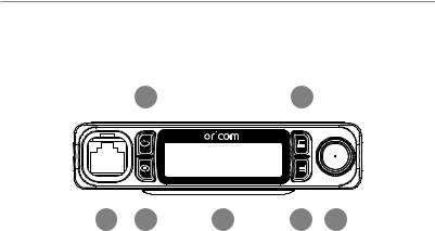
Front View
2 |
4 |
|||
|
|
|
|
|
|
|
|
|
|
|
|
|
|
|
|
|
|
|
|
|
|
|
|
|
|
|
|
|
|
|
|
|
|
|
|
|
|
|
|
|
|
|
|
|
|
|
|
|
|
|
|
|
|
|
1 |
3 |
7 |
5 |
6 |
|||||
1.Microphone connector
2.Open Scan/Priority Scan
3.Memory Scan/Group Tone Scan
4.Memory recall/Memory write
5.Remove memory/Menu
6.Volume/Channel/Squelch
7.LCD display
4
Controls and Indicators
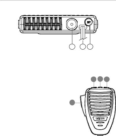
Rear View
1 2 3
1.Antenna Connection
2.Power supply connection
3.3.5mm external jack for optional 8 ohm speaker
Microphone |
2 |
3 |
4 |
||
1. |
Push to talk |
||||
|
|
|
|||
2. |
Volume/Channel/SQ down |
|
|
|
|
3. |
Mode On/off switch |
|
|
|
|
4. |
Volume/Channel/SQ up |
1 |
|
|
|
|
|
|
|
||
5
Controls and Indicators
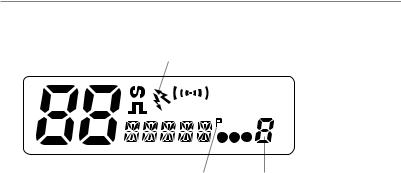
LCD Icons & Indicators
1 |
2 |
3 |
4 |
|
|
|
5 |
|
|
|||||||||
|
|
|
|
|
|
|
|
|
|
|
|
|
|
|
|
|
|
|
|
|
|
|
|
|
|
|
|
|
|
|
|
|
|
|
|
|
|
|
|
|
|
|
|
|
|
|
|
|
|
|
|
|
|
|
|
|
|
|
|
|
|
|
|
|
|
|
|
|
|
|
|
|
|
|
|
|
|
|
|
|
|
|
|
|
|
|
|
|
|
|
|
|
|
|
|
|
|
|
|
|
|
|
|
|
|
|
|
|
|
|
|
|
|
|
|
|
|
6 |
|
|
7 |
|
9 |
|
8 |
||||
1. |
Channel display |
6. |
Priority |
|
|||
2. |
CTCSS or DCS on |
7. |
Memory Group number |
||||
3. |
Duplex On |
8. |
Memory Group I II or III |
||||
4. |
Channel busy indicator |
9. |
Status display |
||||
5. |
Signal strength & TX |
|
|
|
|
|
|
6

Important information
Please read before installing or operating your Oricom Radio
The operation of your UHF radio in Australia and New Zealand is subject to conditions in the following licenses:
In Australia the ACMA Radio communications (Citizen Band Radio Stations) and in New Zealand by MED the General User Radio License for Citizen Band Radio.
Safety Information and Warnings
Potentially Explosive Atmospheres
 Turn your radio OFF when in any area with a potentially WARNING explosive atmosphere. Sparks in such areas could cause an
explosion or fire resulting in injury or even death.
NOTE: Areas with potentially explosive atmospheres are often, but not always clearly marked. They include fueling areas such as below deck on boats; fuel or chemical transfer or storage facilities; areas where the air contains chemicals or particles, such as grain, dust, or metal powders; and any other area where you would normally be advised to turn off your vehicle engine.
Blasting Caps and Areas
To avoid possible interference with blasting operations, turn your radio OFF near electrical blasting caps or in a "blasting area" or in areas posted: "Turn off two way radios." Obey all signs and instructions.
Electromagnetic Interference/Compatibility
Nearly every electronic device is susceptible to electromagnetic interference (EMI). To avoid the possibility of electromagnetic interference and/or compatibility conflicts, turn off your radio in any location where posted notices instruct you to do so such as health care facilities.
7

Installation of your Oricom Radio
When installing your radio in your vehicle, check that
 during installation you do not damage any wiring or vehicle CAUTION components that may be hidden around the mounting position.
Ensure the installation does not interfere with the operation of the vehicle and meets all regulatory and safety retirements for accessories fitted to your vehicle.
For optimum performance your radio needs to be installed correctly. If you are unsure about how to install your radio, we suggest you have your radio professionally installed by a UHF specialist or Auto electrician. When installing the radio, avoid mounting it close to heaters or air conditioners. Never press the PTT or CALL button before connecting the antenna to the radio.
Wiring Methods
There are two possible wiring configurations for connecting to the
Vehicles power supply.
A. Radio stays ON when the ignition is switched OFF
Connect the radio's negative (black) lead to the vehicle chassis, or directly to the batteries negative terminal.
Connect the radio's positive (red) lead via the 2 Amp fuse to the battery's positive terminal. Alternatively, the positive lead could be connected at the fuse box at a point that has DC Power continuously available (preferably the battery side of the ignition switch) via the 2 Amp fuse.
B. Radio turns OFF with the ignition switch
Connect the radio's negative (black) lead to the vehicle's chassis, or directly to the batteries negative terminal.
8

Installation of your Oricom Radio
The radio's positive (red) lead should connect to an accessory point in the vehicle's fuse box via the 2 Amp fuse.
Antenna information
The antenna (not supplied) is of critical importance, to maximize your output power and receiver senstivity.
A poorly installed, inferior quality antenna or one not designed for the correct frequency band will give poor performance. You should only purchase an antenna designed for the 477MHz frequency band.
Antenna installation
1.Connect the antenna to the rear antenna socket using a PL259 coaxial connector (not supplied).
2.To obtain maximum performance from the radio, select a high quality antenna and mount it in a good location. Never press the PTT or
CALL button before connecting the antenna to the radio.
Optional accessories
If required you may install an external (8 ohm, max 5w power) speaker fitted with a 3.5mm plug (not supplied).
Depending on the installation it may be necessary to use an external speaker (not supplied) to give improved volume and clarity. This can be plugged into the external speaker (SP) socket on the rear of the unit.
9

Operations
Operations
Turning on the Power
Press and hold the Channel selector.
Setting the Volume
Turn the channel selector clockwise to adjust the sound level for comfortable reception.
On the microphone push the up or down buttons to increase or decrease the volume. If held down the volume will increase or decrease quickly.
Selecting a channel
Press channel selector once. "CH" will appear on the LCD. Select the channel by rotating the channel knob.
On the microphone push the mode button and select the channel using the up or down buttons.
10
 Loading...