


User’s Manual – Optoma ZF2100 System: Optoma ZF2100 Glasses and Optoma BC100B Emitter for Optoma 3D Projectos and 3D XL Converter Box
Contains Patent Pending software and technology from Bit Cauldron
Contient les logitiels de brevet en instance et la technologie de la compagnie Bit Cauldron
Optoma BC100B Emitter Manual
The Optoma BC100B Emitter connected to Optoma 3D XL converter box or Optoma 3D Projector enables ultimate 3D stereoscopic viewing with Optoma ZF2100 LCD Shutter Glasses. Optoma BC100B Emitter is also compatible with first generation Optoma ZF2100 LCD Shutter Glasses. First generation Optoma BC100 Emitter is also compatible with Optoma ZF2100 LCD Shutter Glasses. This document describes the features, connection, setup, and operation of the Optoma BC100B Emitter with Optoma 3D projector or Optoma 3D XL converter box.
Features
•RF synchronization for uninterruptable 3D glasses performance
•Ready to watch compatibility with 3D Ready Optoma projectors with Optoma 3D XL converter box
•LED indicators assist with IR Sensor placement
•Management Software enables Upgrade functionality for compatibility with future 3D TVs
•Manual performance adjustment capability
[This manual is intended to be repurposed by OEM’s in the creation of their manual. Insert your product shot or quick start image here.]
Copyright 2011 Bit Cauldron Corporation |
Page 1 of 28 |

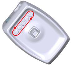
Connections
Optoma 3D XL converter box with 3D E mitter Port
1: Connec t the Optoma BC100B Em itter to the O ptoma 3D X L converter box using the IR Emitter Po rt as shown below.
Optoma 3D Projector with VE SA 3D Por t
2: Connec t the Optoma BC100B Em itter to the V ESA 3D port of Optoma 3D projector as shown belo w.
|
|
|
|
Copyright 2011 Bit Cau ldron Corpo ration |
|
Page 2 of 28 |
|
|
|||
|
|||
Basic Features
RF Communication of Synchronization Signal
RF communications enables the Optoma ZF2100 System to provide an awesome and uninterruptable 3D viewing experience. Line of sight obstructions, emitter placement and viewer seating arrangements have no impact on the performance of the emitter to glasses synchronization. Optimal seating distance and viewing angle is determined by the capabilities of the 3D Ready Projector coupled to the Optoma 3D XL converter box and ZF2100 System.
Copyright 2011 Bit Cauldron Corporation |
Page 3 of 28 |
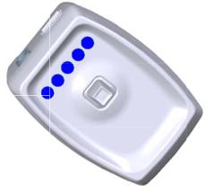
LED Indicators
The Optoma BC100B E mitter uses 5 multicolored LEDs to indicate modes of operation or other inform ation. The LEDs are located on the top o f the emitter close to the joystick and display red, blue, or purple.
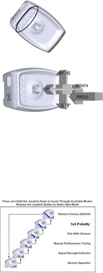
Joystick
The Opt ma BC100B Emitter us es a joystick to allow the user to enab le various modes and cha nge settings. The joystick has two axes and a center button function. Fun tion of the a xes and but tons are depe ndent on the operating mode as described in following sections.
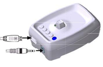
Modes of Operatio n
The Optoma BC100B Emitter has 5 modes of op eration.
•Normal
•Sync Signal Status (Strength)
•Manu al Tuning of Glasses Perfo rmance
•Pairin g the Optoma BC100B Em itter with Op toma ZF210 0 Glasses
•Set P olarity
Accessing Modes
During n ormal operation, the joys tick is used to access different mod es of operation. Press and hold the joystick to cycle throug h the availa ble modes. R elease the j oystick to select a mode. In any mo de, the normal mode of operation resumes after 60 seconds of inac tivity with the exception of Set Polar ty mode. Set Polarity mode will time out in 10 sec onds.
Copyright 2011 Bit Cau ldron Corpo ration |
Page 4 of 28 |
If sync sig nal is present either from VESA or IR Sensor, there will be at least one blue LED on. Moving the joystick in any directio n will not chan ge emitter’s mode. You must press the joystick in an y direction a nd release the joystick so that all LED a re off. Pressi ng the joystick in any direction again will allow you to cycle through all modes.
Copyright 2011 Bit Cau ldron Corpo ration |
Page 5 of 28 |
Normal Operation Mode
During normal operating mode, the Optoma BC100B Emitter interprets 3D signals from the 3D XL converter box and controls the Optoma ZF2100 Series LCD Shutter Glasses through RF. No LEDs are active.
Signal Status (Strength) Indicator Mode
The signal status (strength) indicator provides a visual signal status measurement. The number of lit blue LEDs indicates the quality of the sync signal, with more blue LEDs equating to better Sync signal. The LEDs will display a red moving pattern while the emitter is attempting to acquire a 3D signal and until a signal is found.
Manual Performance Tuning Mode
The Optoma BC100B Emitter and Optoma ZF2100 LCD Shutter Glasses are preprogrammed to work with a wide variety of TVs and 3D content. The manual performance tuning mode enables the 3D system performance to be fine tuned. Warning, use of this feature can result in improper or undesirable operation.
3D Emitter & Glasses Pairing Mode
In environments where more than one Optoma BC100B Emitter is present, Optoma ZF2100 Glasses should be paired with the emitter to ensure proper operation. This mode also involves the Optoma ZF2100 Glasses and is described in greater detail in a subsequent section.
Set Polarity Mode
This mode allows manual setting of lens polarity. During normal operation left lens will open when rising sync edge is detected. Polarity can be reversed so that right lens will open when rising sync edge is detected.
Factory Defaults Mode
In the event that the Optoma BC100B Emitter is not working properly and other troubleshooting methods have failed, use the Reset to Factory Defaults mode to attempt recovery of proper operation. Warning: Any tuning done using Manual Performance Tuning will be erased.
Connecting the Optoma BC100B Emitter to Optoma 3D XL converter box or Optoma 3D Projector
Use the guide in Connections: Optoma 3D XL converter box with 3D Emitter Port to properly connect the Optoma BC100B Emitter. When the Optoma 3D XL converter box receives 3D signal or Optoma 3D projector is playing 3D signal, the Optoma BC100B Emitter will turn on as well. The LEDs will display a red moving pattern while the
Copyright 2011 Bit Cauldron Corporation |
of 28 |
emitter is attempting to acquire a 3D signal a nd until a sig nal is found . If the emit ter searches for a signal for longer than 60 seconds, a signal is n ot found. Ensure that t he 3D ready projector is in 3D mode. In addition to setting the 3 D ready proje ctor in 3D mode, you must also have 3D content playing in order to find 3D sig al (LED’s turn blue.)
Upon fin ding a 3D signal, all LEDs will turn blue fo r approximately 60 sec onds and then turn off. Once the LED s indicate a 3D signal, th e Optoma Z F2100 Glasse s can be used to experience 3D. If the image when viewe d through the Optoma ZF2100 Glasses is fuzzy, has ghostin g, or is out of polarity, see Manual Performance Tuning Mod e: Using the Joystick t o Manually T une Perform ance.
Manual Performan ce Tuning Mode: Using the Joy stick to Manually Tune Perform ance Mode
During performance tu ning, the Optoma BC100 B Emitter con tinues to pro vide 3D sync to the Opto ma ZF2100 G lasses. The joystick modifies paramet ers, while the LEDs display the current value of the parameter being adjusted. While w earing the Optoma ZF2100 Glasses a nd viewing 3 D content on the projector, hold the Optoma BC100 B Emitter and adjust the parameters to the desired settings.
WARNIN G: THE MANU AL PERFORM ANCE TUNIN G MODE EN ABLES THE U SER TO PLAC E THE GLASSE S IN A MODE IN WHICH ON E EYE SEES A DOUBLE IM AGE CONSISTING OF PARTS OF BOTH THE LEFT AND RIGHT IMAGE. THIS CA N CAUSE EYE STRAIN. IF Y OU EXPERIEN CE EYESTRAIN, PLEASE DISCONTINUE USE OF THE P RODUCT IMM EDIATELY. T O MINIMIZE THE CHANCE S OF EXPERIENCING EYEST RAIN DURING MANUAL PERFORMAN CE TUNING, PLEASE OPEN ONLY ONE EYE AT A TIME. THIS METH OD ALSO M AKES IT EASIER TO PERFORM PERFORMANCE TUNING. AFTER EAC H EYE SEES A UNIQUE IMAGE, OPEN BO TH EYES AT THE SAME TIM E TO CHECK THE POLARI TY.
LED Display During Performance T uning
When the device enters manual performance tuning mode, the display will change from two blue LED’s to some n umber of re d LED’s indica ting the current delay. [N ote: if the d elay has previously been tuned to the mi nimum value, the displayed value will c orrespond to zero and all LED’s will appear dark.]
To provide adequate time for adjustment and o bservation of the current settings, performance tuning mode stays active for two minutes after the user stops opera ting the joystick. Following the inacti vity
Copyright 2011 Bit Cau ldron Corpo ration |
Page 7 of 28 |
period, th e performance tuning settings will be saved and th e Optoma BC100B Emitte r will return to normal o perating mode.
See the appendix Abo ut Performance Tuning for a detailed explanation of shutter glass function and performance tuning.
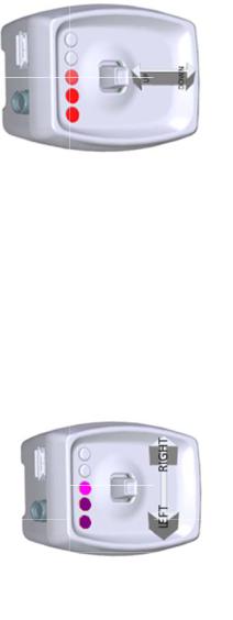
Delay Tu ning
Moving t he joystick up and down w ill change th e delay betw een when th e “Open Left” signal is rec eived by the em itter and when the left lens opens. (Th e delay of the right lens w ill also be changed in lock step, as will the lens closing times.)
UP = INCR EASE DELAY, GAUGE GOES UP
DOWN = DECREASE DE LAY, GAUGE GOES DOWN
As the delay is changed, a bar of re d LED’s will m ove up and down to form a gauge of the delay. Eac h of the five L ED’s will mar ch through fo ur visibly dif ferent bright ness levels, r esulting in 20 possible visible values for delay. With a small tap t he transmitter will actuall y change dela y by a small amount not visible on the LED display. If up or d own is pressed and held, the gauge will move quick ly through th e values. If up or down is pressed and released, t he delay will change by a unit one quarter the size o f a visible ch ange in lighti ng. It takes fo ur taps in th e same direct ion to make a visible cha nge in the ga uge.
Lens Duty Cycle Tuning
Moving t he joystick lef t and right will change th e total time t he glasses op en each lens.
LEFT = CLOSE LENSES MORE, BRIGH TNESS GOES DOWN, GHO STING MAY GO
DOWN
RIGHT = O PEN LENSES MORE, BRIGHTNESS GOES UP, GHOSTING MAY GO UP
As the duty cycle is ch anged, a bar of purple LED ’s will move up and down to form a gauge of the de lay. (Other t han color, th e delay gauge and the duty cycle gau ge have the same appeara nce; which gauge is displayed is
determined by which direction has been presse d last.) Each of the five LE D’s will marc h through fou r visibly different brightness levels (resulting in 20 possible visible values for duty cycle.) With a small tap the trans mitter will actually change duty cycle by a small am ount not visib le on the LE D display. If le ft or right is pressed and held, the gauge will move q uickly through the values. If left or right is pressed and released, the delay will change by a unit one qu arter the size of a visible change in lighting. It takes four
Copyright 2011 Bit Cau ldron Corpo ration |
Page 8 of 28 |
taps in the same direction to make a visible change in the gauge; in certain lighting conditions a single tap may be visible as a change in brightness viewed through the glasses.
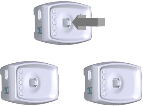
Set Polarity
It is possible that the 3D image, although perfectly clear and free of ghosting, looks incorrect or shows no depth. The polarity could be reversed, which means the left lens is open when the right eye image is being displayed – the left eye is getting the right image and vice versa. Simply place the glasses upside down over your eyes to check if the image is now corrected. If the 3D image is better, the polarity is reversed. Reversal of polarity can be caused by the source, the content or the projector. The source equipment or the 3D ready projector may have an option to correct this. If not, the Optoma BC100B Emitter can be used to reverse polarity.
•Select the Manual Tuning Performance Mode, see the Accessing Modes section
•Press and release the joystick
•If the polarity changes to standard, two red LEDs will be lit
•If the polarity changes to reverse, three red LEDs will be lit
•While wearing 3D glasses, view 3D content to ensure proper polarity
•Repeat until correct polarity is selected
PRESS JOYSTICK DIRECTLY INTO EMITTER = SWITCH POLARITY
PRESS
STANDARD POLARITY |
REVERSE POLARITY |
Once the correct polarity is achieved, stop pressing the joystick. After 120 seconds, the LEDs will turn off, indicating that the new polarity setting has been saved. This polarity setting will be saved and used
Copyright 2011 Bit Cauldron Corporation |
Page 9 of 28 |
 Loading...