

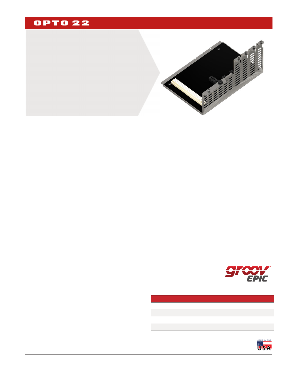
groov EPIC Chassis
Features
Secure mounting for power supply and processor, with or
>
without groov® I/O modules
Mount on a panel or 35 mm DIN-rail
>>
Modules pivot into place, plug into a module connector, and
>
lock onto the chassis with a single screw
Processor and power supply interlock and are secured with a
>
screw
UL Hazardous Locations approved and ATEX compliant
>>
DATA SHEET
Form 2247-190925
PAGE 1
GRV-EPIC-CHS4
DESCRIPTION
All groov EPIC® I/O mounting chassis are designed to hold an
intelligent groov EPIC processor and power supply, with models
available that can also hold 0, 4, 8, or 16 groov I/O modules.
The GRV-EPIC-CHS4, GRV-EPIC-CHS8, and GRV-EPIC-CHS16 can
hold a mix of groov analog, discrete, and serial I/O modules, because
all modules have the same footprint. Analog and discrete modules
can be placed in any module position on the chassis. Serial modules
can be placed in any of the first four positions and are directly
connected to the groov EPIC processor via the bus on the chassis.
Field devices are wired directly to the top-mounted connectors on the
modules. The module and chassis design allows each module to pivot
into a specific mounting position on the chassis.
The GRV-EPIC-CHS0 mounts the processor and power supply only
(no I/O modules) and is ideal for applications where I/O is not needed
and cabinet space is at a premium.
A Complete I/O Unit Where You Need It
With a GRV-EPIC-CHS4, GRV-EPIC-CHS8, or GRV-EPIC-CHS16, you can
have a powerful I/O unit wherever you need it. From small
applications in a limited physical space, to larger applications with
complex requirements, the three models are designed to meet a large
range of application requirements and physical space limitations.
Beyond a PLC – Processing Power at the Edge
With a GRV-EPIC-CHS0, you can put a groov EPIC processor
(GRV-EPIC-PR1) in tough, industrial locations where typical computers
or networking equipment may not be able to operate. The processor
can provide the computing power and networking connectivity you
need to modernize and extend your applications and systems. To
learn more about the capabilities of the groov EPIC processor, see
groov EPIC Processor Data Sheet (form 2245).
Agency Approvals and Compliance
All groov power supplies, voltage converters, pass-through power
adapters, I/O modules, and processors are UL/cUL listed and
compliant with the ATEX, Low Voltage, and EMC CE directives. Each
module is factory tested twice before shipment and most modules
are guaranteed for life.
Part Numbers
Part Description
GRV-EPIC-CHS0 Processor and power supply only mounting chassis
GRV-EPIC-CHS4 4-module analog/discrete/serial mounting chassis
GRV-EPIC-CHS8 8-module analog/discrete/serial mounting chassis
GRV-EPIC-CHS16 16-module analog/discrete/serial mounting chassis
© 2018-2019 Opto 22. All rights reserved. Dimensions and specifications are subject to change. Brand or product names used herein are trademarks or registered trademarks of their respective companies or organizations.
SPECIFICATIONS
All specifications assume the following:
The air temperature 1 inch below the bottom of the chassis vents
does not exceed 70 °C.
The vents are unobstructed.
The chassis is mounted in a horizontal orientation with the back
of the unit mounted on a vertical surface.
Specification GRV-EPIC-CHS16 GRV-EPIC-CHS8 GRV-EPIC-CHS4 GRV-EPIC-CHS0
Number of module slots
Maximum Power Rating
Temperature (operating)
Temperature (storage)
Humidity (non-condensing)
Agency Approvals
Warranty
16840
UL/cUL(Class 1 Div. 2), CE, ATEX(Category 3, Zone 2), RoHS, DFARS; CB Scheme
For a diagram that shows the bottom of the chassis, see “Overall
Dimensions with Power Supply, Processor, and Modules Mounted” on
page 4. For a diagram that shows the chassis in standard orientation,
see “Orientation and Clearances” on page 5.
60 W with GRV-EPIC-PSAC
50 W with GRV EPIC PSDC
108 W with GRV-EPIC-PSPT
-20 °C to +70 °C
-40 °C to +85 °C
5–95% RH
30 months
DATA SHEET
Form 2247-190925
PAGE 2
DIMENSIONS: GRV-EPIC-CHS0, GRV-EPIC-CHS4, GRV-EPIC-CHS8, AND
GRV-EPIC-CHS16
If you want to import these dimensions into an AutoCAD software system, go to the Opto 22 website and download CAD Drawings: groov EPIC
chassis.
Part Number Description Width (inches) Width (mm) Length (inches) Length (mm) Depth (inches) Depth (mm)
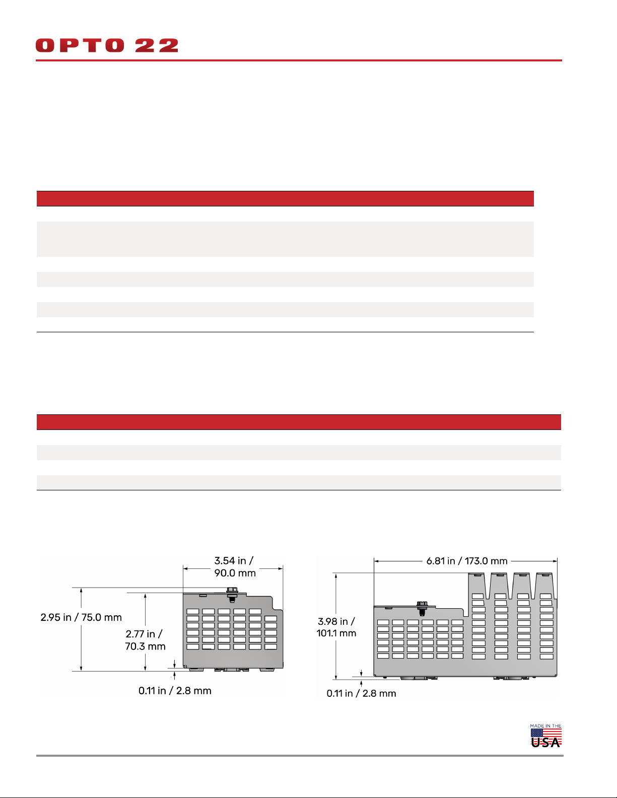
GRV-EPIC-CHS0 0-module chassis 5.36 136.2 3.54 90.0 2.95 101.1
GRV-EPIC-CHS4 4-module chassis 5.36 136.2 6.81 173.0 3.98 101.1
GRV-EPIC-CHS8 8-module chassis 5.36 136.2 10.18 258.5 3.98 101.1
GRV-EPIC-CHS16 16-module chassis 5.36 136.2 16.91 429.6 3.98 101.1
Depth and Length Dimensions
These diagrams show the bottom view of the chassis.
GRV-EPIC-CHS0 GRV-EPIC-CHS4
© 2018-2019 Opto 22. All rights reserved. Dimensions and specifications are subject to change. Brand or product names used herein are trademarks or registered trademarks of their respective companies or organizations.
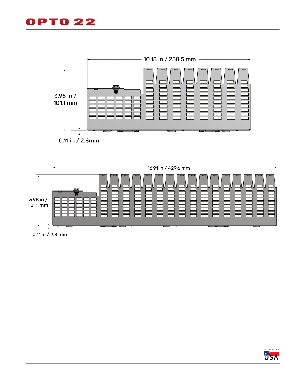
GRV-EPIC-CHS8
GRV-EPIC-CHS16
DATA SHEET
Form 2247-190925
PAGE 3
© 2018-2019 Opto 22. All rights reserved. Dimensions and specifications are subject to change. Brand or product names used herein are trademarks or registered trademarks of their respective companies or organizations.

DATA SHEET
Form 2247-190925
PAGE 4
Overall Dimensions with Power Supply, Processor, and Modules Mounted
The following diagrams show the dimensions of a 16-module chassis with a power supply, processor, and 16 modules mounted on it, with the
touchscreen open in a two different positions. The DIN rail shown is a standard 35 mm DIN rail (not sold by Opto 22). When you are determining
a location for the chassis, ensure you comply with the orientation and clearances indicated in “Orientation and Clearances” on page 5.
End View
The dimensions shown in the diagram to the right show the
touchscreen in two positions:
Open. Those are the dimensions at the top of the diagram.
Closed. Those are the dimensions at the bottom of the diagram.
Back View
The dimensions shown in the following diagram indicate the distance between the DIN rail (if used) and the edges of the chassis and the edges
of the unit (if modules are mounted to the chassis). The view shows the touchscreen open upright, perpendicular to the view.
© 2018-2019 Opto 22. All rights reserved. Dimensions and specifications are subject to change. Brand or product names used herein are trademarks or registered trademarks of their respective companies or organizations.

Bottom View
The dimensions in the following diagram show the display open in two positions: upright and out to its fullest extension.
DATA SHEET
Form 2247-190925
PAGE 5
ORIENTATION AND CLEARANCES
The diagrams in this section show the orientation and the clearances
recommended to ensure compliance with the specifications.
The diagram below shows a chassis (with modules, power supply, and
groov EPIC processor mounted on the chassis) with arrows indicating
a minimum 2 inch clearance all around the unit.
2 inches
2 inches
2 inches
2 inches
The diagram below shows the chassis mounted in a cabinet in a
horizontal orientation.
© 2018-2019 Opto 22. All rights reserved. Dimensions and specifications are subject to change. Brand or product names used herein are trademarks or registered trademarks of their respective companies or organizations.

DATA SHEET
Form 2247-190925
PAGE 6
ASSEMBLING AND MOUNTING
Before assembling and mounting your equipment, make sure you have the necessary clearances to ensure good ventilation, and that the area
where you will be installing the equipment does not exceed the specifications listed in “Specifications” on page 2. Check the following:
Ensure that there is a minimum of 2 inches clearance on the top,
bottom, each side, and front of the rack, after the processor,
power supply, and modules are mounted.
Ensure that the vents at the bottom of the chassis are not
obstructed.
Mounting on a DIN Rail
The chassis is built with DIN rail adapters for use on 35 mm DIN rail.
No additional assembly is required.
Mount the empty chassis to the DIN rail before installing the groov
EPIC power supply, processor, or I/O modules.
To mount the chassis to a DIN rail, follow these steps:
1. Hold the chassis so that the module connector numbers are
facing right side up.
2. Hold the chassis at an angle such that the top of the DIN rail
adapter is away from the DIN rail and the bottom of the DIN rail
adapter can slide behind the bottom lip of the DIN rail.
3. Push the bottom part of the chassis upward, making sure that you
feel the clip catch on to the rail, and simultaneously push the top
half of the chassis toward the DIN rail until the top of the DIN rail
adapter engages the top lip of the DIN rail.
Before you release the chassis, verify that the top and bottom of
the DIN rail adapters have engaged the DIN rail.
4. For all chassis models, mount the power supply and the
processor. For the chassis models that also hold groov I/O
modules, mount the modules onto the chassis.
When you choose a mounting location, ensure that the location
complies with the orientation and clearances specified in
“Orientation and Clearances” on page 5.
Mounting on a Panel
Using Chassis as Template
Use this method if you have the chassis on hand to use as a template.
1. Review the mounting hole dimensions on the next page and the
dimensional drawings in previous pages to determine required
product and option clearances.
2. Opto 22 ships the backplane attached to the chassis, so remove
the backplane to gain access to the chassis mounting holes.
Alternate Method: Prefabrication of Panels
If you do not have the chassis on hand, review the diagrams on the next page to determine mounting hole positions.
© 2018-2019 Opto 22. All rights reserved. Dimensions and specifications are subject to change. Brand or product names used herein are trademarks or registered trademarks of their respective companies or organizations.
3. Use the chassis as a template to mark holes.
4. After the chassis is securely mounted, attach the backplane with
the retention screws provided.

DATA SHEET
Form 2247-190925
PAGE 7
Mounting Hole Dimensions
The following diagrams show the length measurements from the edges of the chassis to the center positions of the mounting holes. When you
install the chassis, use pan head screws of up to 10-32 in size.
GRV-EPIC-CHS0 GRV-EPIC-CHS4
GRV-EPIC-CHS8
© 2018-2019 Opto 22. All rights reserved. Dimensions and specifications are subject to change. Brand or product names used herein are trademarks or registered trademarks of their respective companies or organizations.

GRV-EPIC-CHS16
DATA SHEET
Form 2247-190925
PAGE 8
© 2018-2019 Opto 22. All rights reserved. Dimensions and specifications are subject to change. Brand or product names used herein are trademarks or registered trademarks of their respective companies or organizations.

More about Opto 22
PRODUCTS
Opto 22 develops and manufactures reliable, easy-to-use, open
standards-based hardware and software products.
Industrial automation, process control, building automation, industrial
refrigeration, remote monitoring, data acquisition, and industrial
internet of things (IIoT) applications worldwide all rely on Opto 22.
groov EPIC® System
Opto 22’s groov Edge Programmable Industrial Controller (EPIC)
system is the culmination of over 40 years of experience in designing
products for the automation industry.
groov EPIC gives you an industrially hardened system with
guaranteed-for-life I/O, a flexible Linux®-based processor with
gateway functions, and software that meets the needs of your
automation and IIoT applications.
groov EPIC I/O
I/O provides the local connection to
sensors and equipment. groov I/O
offers up to 24 channels on each I/O
module, with a spring-clamp
terminal strip, integrated wireway,
swing-away cover, and LEDs
indicating module health and
digital channel status.
groov I/O is hot swappable, UL
Hazardous Locations approved, and
ATEX compliant. Opto 22 I/O is so
reliable, we guarantee it for life.
Optional access to the Linux operating system through a secure
shell (SSH) to download and run custom applications
groov View for building your own device-independent HMI,
viewable on the touchscreen, PCs, and mobile devices.
Node-RED for creating simple logic flows from pre-built nodes
Ignition Edge® from Inductive Automation®, with OPC-UA drivers
to Allen-Bradley®, Siemens®, and other control systems, and
MQTT/Sparkplug communications for efficient IIoT data transfer
Older products
From solid state relays (our first products) to world-famous G4 and
SNAP I/O, to SNAP PAC controllers, older Opto 22 products are still
supported and still doing the job at thousands of installations
worldwide. You can count on us to give you the reliability and service
you expect, now and in the future.
QUALITY
Founded in 1974, Opto 22 has
established a worldwide reputation
for high-quality products. All are
made in the U.S.A. at our
manufacturing facility in Temecula,
California.
Because we test each product twice
before it leaves our factory rather than
testing a sample of each batch, we
can afford to guarantee most solidstate relays and optically isolated I/O
modules for life.
groov EPIC Processor
The heart of the system is the groov EPIC processor. It handles a wide
range of digital, analog, and serial functions for data collection,
remote monitoring, process control, and discrete and hybrid
manufacturing.
In addition, the EPIC provides secure data communications among
physical assets, control systems, software applications, online services,
and more, both on premises and in the cloud.
Configuring and troubleshooting I/O and networking is easier with
the EPIC’s integrated high-resolution color touchscreen. Authorized
users can manage the system locally on the touchscreen or on a
monitor connected via the HDMI or USB ports.
groov EPIC Software
Software included in the groov EPIC controller:
PAC Control engine to run PAC Control strategies and PAC Display
projects
CODESYS Runtime engine to run IEC61131-3 compliant programs
built with CODESYS Development System
© 2001–2019 Opto 22. All rights reserved. Dimensions and specifications are subject to change. Brand or product names used herein are trademarks or registered trademarks of their respective companies or organizations.
Form 1335-190917
 Loading...