


Cat. No. 31-3038
Digital Synthesize
Audio/Video
Surround Receive
STAV-3590
|
|
|
|
|
|
|
|
|
|
|
|
|
|
|
|
|
|
|
|
|
|
|
|
|
|
|
|
|
|
|
|
|
|
|
|
|
|
|
|
|
|
|
|
|
|
|
|
|
|
|
|
|
|
|
|
|
|
|
|
|
|
|
|
|
|
|
|
|
|
|
|
|
|
|
|
|
|
|
|
|
|
|
|
|
|
|
|
|
|
|
|
|
|
|
|
|
|
|
|
|
|
|
|
|
|
|
|
|
|
|
|
|
|
|
|
|
|
|
|
|
|
|
|
|
|
|
|
|
|
|
|
|
|
|
|
|
|
|
|
|
|
|
|
|
|
|
|
|
|
|
|
|
|
|
|
|
|
|
|
|
|
|
|
|
|
|
|
|
|
|
|
|
|
|
|
|
|
|
|
|
|
|
|
|
|
|
|
|
|
|
|
|
|
|
|
|
|
|
|
|
|
|
|
|
|
|
|
|
|
|
|
|
|
|
|
|
|
|
|
|
Owner’s Manual |
|
|
Please read before using this equipment. |
|||||||||||||||
|
|
|
|
|
|
|
|
|
|
|
|
|
|
|
|
|
|
|
|

Introducing the Optimus STAV-3590
Your Optimus STAV-3590 Digital Synthesized A/V Surround Receiver is the perfect control center for your audio/video system. It combines 150 watts-per-chan- nel of clean power with modern styling and provides connections for one tape deck, one audio/video source, one more tape deck or audio/video playback source, a turntable, a CD player, and a video monitor.
Your receiver also has special sound options. Dolby Pro-Logic Surround Sound delivers movie theater sound for audio/video programs (especially those encoded with Dolby Surround Sound signals). Dolby 3CH Logic provides a wider sound field than ordinary playback. Studio Effect simulates the ambiance of a recording studio, adding extra richness to your music. Arena creates a listening environment that simulates a concert hall or a movie theater. Simulated Surround gives you a surround-sound effect even when you listen to monaural sources.
Additional features include:
Digital-Synthesized Tuner Precisely tunes to AM and FM stations.
Multi-Jog Tuning Offers you a simple tuning method for either memorized stations or the entire frequency range.
Automatic Tuning Searches for the next available AM/FM station.
30 Memory Locations Let you store and recall the frequencies for up to 30 AM/FM stations.
Subwoofer Output Lets you easily connect an amplified subwoofer that delivers the very low frequency bass sounds, bringing out the richness and depth of music plus the full impact of motion-picture special effects for sound you can actually feel.
Super Bass Creates a richer, fuller sound by enhancing the audio program’s bass.
Tape Monitoring Lets you listen to the actual recording as you record, if your tape deck has a tape-monitoring feature.
Built-In Protection Circuits Turn off the receiver to help avoid power surge or short circuit damage.
Trainable Remote Control Lets you use a single remote control for the receiver and other compatible components connected to the receiver.
Display Blanking Lets you turn off the display so the light does not disturb you in low-light situations.
For your records, record the receiver’s serial number here. The serial number is on the receiver’s back panel.
Serial Number:_____________________________________________
Note to the Cable TV System Installer:
This reminder is provided to call the CATV system installer’s attention to article 820-40 of the National Electrical Code that provides guidelines for proper grounding and, in particular, specifies that the cable ground shall be connected to the grounding system of the building as close to the point of cable entry as practical.
Manufactured under license from Dolby Laboratories Licensing Corporation.
Additionally licensed under one or more of the following Patents: U.S. Number 3,959,590; Canadian Numbers 1,004,603 and 1,037,877. Dolby, Pro Logic, and the double-D  symbol are trademarks of Dolby Laboratories Licensing Corporation.
ã 1996 Tandy Corporation.
All Rights Reserved.
Optimus is a registered trademark used by Tandy Corporation. RadioShack is a trademark used by Tandy Corporation.
2
IMPORTANT SAFETY INSTRUCTIONS
This receiver is made and tested to meet exacting safety standards. It meets both UL and FCC requirements.
WARNING: TO REDUCE THE RISK OF FIRE OR ELECTRIC SHOCK, DO NOT EXPOSE THIS APPLIAANCE TO RAIN OR MOISTURE.
To prevent fire or shock hazard, do not expose this system to rain or moisture.
|
CAUTION |
! |
|
|
|
|
RISK OF ELECTRIC SHOCK. |
|
|
|
|
|
DO NOT OPEN. |
|
|
|
|
CAUTION: TO REDUCE THE RISK OF ELECTRIC SHOCK, DO NOT REMOVE COVER OR BACK. NO USER-SERVICE- ABLE PARTS INSIDE. REFER SERVICING TO QUALIFIED PERSONNEL.
This symbol is intended to alert you to the presence of uninsulated dangerous voltage within the system’s enclosure that might be of sufficient magnitude to constitute a risk of electric shock. Do not open the system’s case.
This symbol is intended to inform you that im-
!portant operating and maintenance instructions are included in the literature acc-
ompanying this system.
CAUTION
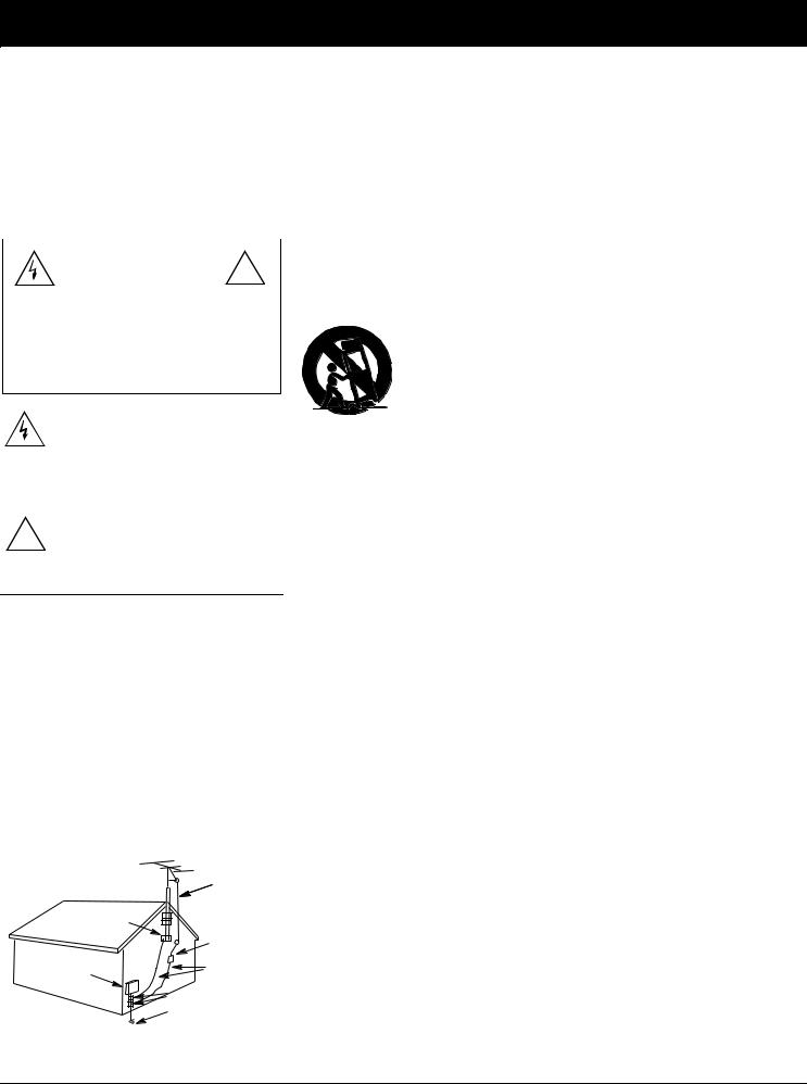
Power Lines—Locate an outdoor antenna away from power lines.
Nonuse Periods—Unplug the receiver’s power cord when you will not use it for extended periods.
Outdoor Antenna Grounding—If an outside antenna or cable system is connected to the receiver, ground the antenna or cable system so as to provide some protection against voltage surges and built-up static charges. Article 810 of the National Electrical Code, ANSI/NFPA 80, provides information about proper grounding of the mast and supporting structure, grounding of the lead-in wire to an antenna discharge unit, size of grounding conductors, location of antennadischarge unit, connection to grounding electrodes, and requirements for the grounding electrode. See the example below.
|
Antenna |
|
|
Lead-In |
|
|
Wire |
|
Ground Clamp |
|
|
|
Antenna |
|
|
Discharge Unit |
|
Electric |
(NEC Section 810-20) |
|
Service |
Grounding Conductor |
|
Equipment |
(NEC Section 810-21) |
|
|
Grounding Clamps |
|
|
Power Service Grounding |
|
NEC -- National Electrical Code |
Electrode System |
|
(NEC Article 250, Part H) |
||
|
Careful attention is devoted to quality standards in the manufacture of your receiver, and safety is a major factor in its design. However, safety is also your responsibility.
This section lists important information that will help you properly use and enjoy your receiver and accessories. Read all the included safety and operating instructions before using your receiver. Follow them closely, and retain them for future reference.
Heed Warnings — Follow all warnings on the product and in the operating instructions.
Cleaning — Unplug this product from the wall outlet before cleaning. Use only a damp cloth fo r cleaning. Do not use liquid or aerosol cleaners.
Attachments — Do not use attachments/accessories not recommended by the product manufac - turer, as they might create a hazard.
Water and Moisture — Do not use this product near water (for example, near a bathtub, washbowl , kitchen sink, or laundry tub; in a wet basement; or near a swimming pool).
Accessories — Do not place this product on an unstable cart, stand, tripod, bracket, or table. Th e product may fall, causing serious injury to a child or adult, and serious damage to the product. Use only with a cart, stand, tripod, bracket, or table recommended by the manufacturer or sold with the product. Follow the manufacturer's instructions for mounting, and use a recommended mounting accessory.
Carts — Move the product on a cart carefully. Quick stops, excessive force, an d uneven surfaces may cause the product/cart to overturn.
Ventilation — Slots and openings in the cabinet provide ventilation, ensure reli - able operation, and protect from overheating. Do not block or cover these openings, and do not place the product on a bed, sofa, rug, or other similar surface. Do not place the product in a built-in bookcase or rack unless it provides proper ventilation as specified by the manufacturer.
Power Sources — Operate this product using only the power source indicated on its marking label . If you are not sure of your home's power type, consult your product dealer or local power company.
Polarization — This product is equipped with a polarized AC line plug (a plug having one blad e wider than the other). This plug will fit in the power outlet only one way. This is a safety feature. If you cannot insert the plug fully into the outlet, try reversing the plug. If the plug still doesn't fit, contact your electrician to replace your obsolete outlet. Do not defeat the safety purpose of the polarized plug. If you need an extension, use a polarized cord.
Power-Cord Protection — Route power-supply cords so they are not likely to be walked on o r pinched by items placed on or against them, paying particular attention to cords at plugs, convenience receptacles, and the point where they exit from the product.
Lightning — For added protection for this product during a lightning storm, or when it is left unat - tended and unused for long periods of time, unplug it from the wall outlet and disconnect the antenna or cable system. This will prevent damage to the product due to lightning and power-line surges.
Overloading — Do not overload wall outlets, extension cords, or integral convenience receptacles , as this can result in a risk of fire or electric shock.
Objects and Liquids — Never push objects of any kind into this product through openings, as the y may touch dangerous voltage points or short out parts that could result in a fire or electric shock. Never spill liquid of any kind on the product.
Servicing — Do not attempt to service this product yourself, as opening or removing covers ma y expose you to dangerous voltage or other hazards. Refer all servicing to qualified service personnel.
Damage Requiring Service — Unplug this product from the wall outlet and refer servicing to qual - ified service personnel under the following conditions:
•When the power-supply cord or plug is damaged.
•If liquid has been spilled or objects have fallen into the product.
•If the product has been exposed to rain or water.
•If the product does not operate normally by following the operating instructions. Adjust only those controls that are covered by the operating instructions, as an improper adjustment of other controls may result in damage and will often require extensive work by a qualified technician to restore the product to normal operation.
•If the product has been dropped or damaged in any way.
•When the product exhibits a distinct change in performance.
Replacement Parts — When replacement parts are required, be sure the service technician use s replacement parts specified by the manufacturer or having the same characteristics as the original part. Unauthorized substitutions may result in fire, electric shock, or other hazards.
Safety Check — Upon completion of service or repairs to this product, ask the service technicia n to perform safety checks to determine that the product is in proper operating condition.
Wall or Ceiling Mount — The product should be mounted to a wall or ceiling only as recommende d by the manufacturer.
Heat — The product should be situated away from heat sources such as radiators, heat registers , stoves, or other products (including amplifiers) that produce heat.
3

Contents
Preparing Your Receiver . . . . . . . . . . . . . . . . . . . . . . . . . . . . . . . . . . . . . . . . . . . . . . . . . . . . . . . . . . . . . . . . . . . . . . . . . . . . . .5
Positioning Speakers . . . . . . . . . . . . . . . . . . . . . . . . . . . . . . . . . . . . . . . . . . . . . . . . . . . . . . . . . . . . . . . . . . . . . . . . . . . .5 Connecting Speakers. . . . . . . . . . . . . . . . . . . . . . . . . . . . . . . . . . . . . . . . . . . . . . . . . . . . . . . . . . . . . . . . . . . . . . . . . . . .6 Connecting Program Sources . . . . . . . . . . . . . . . . . . . . . . . . . . . . . . . . . . . . . . . . . . . . . . . . . . . . . . . . . . . . . . . . . . . . .8 Connecting the Antennas. . . . . . . . . . . . . . . . . . . . . . . . . . . . . . . . . . . . . . . . . . . . . . . . . . . . . . . . . . . . . . . . . . . . . . . .10 Using One Remote Control for More than One Unit . . . . . . . . . . . . . . . . . . . . . . . . . . . . . . . . . . . . . . . . . . . . . . . . . . . 12 Installing the Remote Control’s Batteries . . . . . . . . . . . . . . . . . . . . . . . . . . . . . . . . . . . . . . . . . . . . . . . . . . . . . . . . . . . . 12 Using the AC Power Outlet . . . . . . . . . . . . . . . . . . . . . . . . . . . . . . . . . . . . . . . . . . . . . . . . . . . . . . . . . . . . . . . . . . . . . . 13 Connecting to AC Power . . . . . . . . . . . . . . . . . . . . . . . . . . . . . . . . . . . . . . . . . . . . . . . . . . . . . . . . . . . . . . . . . . . . . . . . 13 Demonstration Display . . . . . . . . . . . . . . . . . . . . . . . . . . . . . . . . . . . . . . . . . . . . . . . . . . . . . . . . . . . . . . . . . . . . . . . . 13
Basic Operation . . . . . . . . . . . . . . . . . . . . . . . . . . . . . . . . . . . . . . . . . . . . . . . . . . . . . . . . . . . . . . . . . . . . . . . . . . . . . . . . . . . . 14
Balance Control . . . . . . . . . . . . . . . . . . . . . . . . . . . . . . . . . . . . . . . . . . . . . . . . . . . . . . . . . . . . . . . . . . . . . . . . . . . . . . . 15
Muting the Receiver . . . . . . . . . . . . . . . . . . . . . . . . . . . . . . . . . . . . . . . . . . . . . . . . . . . . . . . . . . . . . . . . . . . . . . . . . . . . 15
Using Headphones . . . . . . . . . . . . . . . . . . . . . . . . . . . . . . . . . . . . . . . . . . . . . . . . . . . . . . . . . . . . . . . . . . . . . . . . . . . . 15
Tuning the Radio . . . . . . . . . . . . . . . . . . . . . . . . . . . . . . . . . . . . . . . . . . . . . . . . . . . . . . . . . . . . . . . . . . . . . . . . . . . . . . 16
Using FM Mono . . . . . . . . . . . . . . . . . . . . . . . . . . . . . . . . . . . . . . . . . . . . . . . . . . . . . . . . . . . . . . . . . . . . . . . . . . . . . . . 17
Using the Auto Source Control . . . . . . . . . . . . . . . . . . . . . . . . . . . . . . . . . . . . . . . . . . . . . . . . . . . . . . . . . . . . . . . . . . 17
Turning Off the Display . . . . . . . . . . . . . . . . . . . . . . . . . . . . . . . . . . . . . . . . . . . . . . . . . . . . . . . . . . . . . . . . . . . . . . . . 17
Using Sleep (Remote Control Only). . . . . . . . . . . . . . . . . . . . . . . . . . . . . . . . . . . . . . . . . . . . . . . . . . . . . . . . . . . . . . . 17
Cassette Deck/VCR Features . . . . . . . . . . . . . . . . . . . . . . . . . . . . . . . . . . . . . . . . . . . . . . . . . . . . . . . . . . . . . . . . . . . . . . . . . . 18
Using the VCR/TAPE 1 Button . . . . . . . . . . . . . . . . . . . . . . . . . . . . . . . . . . . . . . . . . . . . . . . . . . . . . . . . . . . . . . . . . . 18 Using the TAPE 2 MONITOR Button . . . . . . . . . . . . . . . . . . . . . . . . . . . . . . . . . . . . . . . . . . . . . . . . . . . . . . . . . . . . . 18 Recording a Program Source . . . . . . . . . . . . . . . . . . . . . . . . . . . . . . . . . . . . . . . . . . . . . . . . . . . . . . . . . . . . . . . . . . . 18 Dubbing a Cassette Tape. . . . . . . . . . . . . . . . . . . . . . . . . . . . . . . . . . . . . . . . . . . . . . . . . . . . . . . . . . . . . . . . . . . . . . . .19 Playing and Recording Video Tapes . . . . . . . . . . . . . . . . . . . . . . . . . . . . . . . . . . . . . . . . . . . . . . . . . . . . . . . . . . . . . . . 19
Using Advanced Sound Options . . . . . . . . . . . . . . . . . . . . . . . . . . . . . . . . . . . . . . . . . . . . . . . . . . . . . . . . . . . . . . . . . . . . . . .20
Sound Mode Adjustments (Remote Control Only) . . . . . . . . . . . . . . . . . . . . . . . . . . . . . . . . . . . . . . . . . . . . . . . . . . . . .21
Using the Remote Control . . . . . . . . . . . . . . . . . . . . . . . . . . . . . . . . . . . . . . . . . . . . . . . . . . . . . . . . . . . . . . . . . . . . . . . . . . . . 22
Troubleshooting . . . . . . . . . . . . . . . . . . . . . . . . . . . . . . . . . . . . . . . . . . . . . . . . . . . . . . . . . . . . . . . . . . . . . . . . . . . . . . . . . . . . 26
Returning Controls to Factory Defaults . . . . . . . . . . . . . . . . . . . . . . . . . . . . . . . . . . . . . . . . . . . . . . . . . . . . . . . . . . . . . 26
Care and Maintenance . . . . . . . . . . . . . . . . . . . . . . . . . . . . . . . . . . . . . . . . . . . . . . . . . . . . . . . . . . . . . . . . . . . . . . . . . . . . . . . 27 The FCC Wants You to Know . . . . . . . . . . . . . . . . . . . . . . . . . . . . . . . . . . . . . . . . . . . . . . . . . . . . . . . . . . . . . . . . . . . . . . . . . . 28 Specifications . . . . . . . . . . . . . . . . . . . . . . . . . . . . . . . . . . . . . . . . . . . . . . . . . . . . . . . . . . . . . . . . . . . . . . . . . . . . . . . . . . . . . . 29 Index to Features by Control Name . . . . . . . . . . . . . . . . . . . . . . . . . . . . . . . . . . . . . . . . . . . . . . . . . . . . . . . . . . . . . . . . . . . .31
4
Preparing Your Receiver
Caution: Make all the necessary connections before you plug in or turn on the receiver.
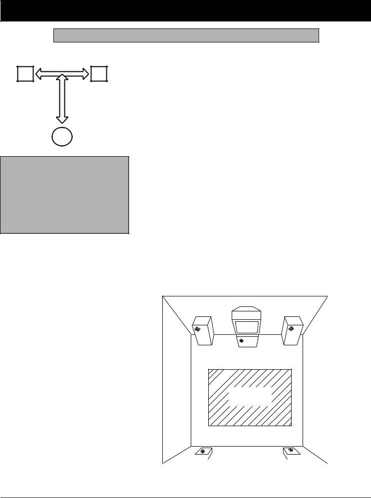
Positioning Speakers
a
L R
Halfway Point
Between Speake
b
a=b
Person in Listening Area
•Surround speakers generally sound best if you position them above ear level.
•To avoid interference with the picture on a nearby TV, use magnetically shielded speaker systems. This is particularly important for the center speaker since it is usually located closest to the TV.
Where you place your speakers (not supplied) can make a noticeable difference in your system’s sound. The guidelines in this section will help you choose the best locations. After you use your receiver for a while, you might want to try different locations for your speakers.
Bass response depends largely on speaker location. For strong bass, place the speakers in the corners of the room. If you want even stronger bass, place the speakers directly on the floor. If the bass is too strong, move the speakers slightly away from the corners of the room, or raise them 6 to 18 inches off the floor. You can buy speaker stands at your local RadioShack store.
The distance between the speakers should be about the same as the distance between the normal listening point and the point halfway between the speakers. If you place the speakers too close together, you reduce the stereo separation. If you place them too far apart, you reduce the bass effect and create a hole in the middle of the sound.
Most speakers have a tweeter dispersion angle of about 60 degrees. Ideally, your listening position should be just inside the overlap area of the tweeter dispersion. You can angle the speakers toward you for better stereo effect.
To position your speakers for surround sound, place the A or B speakers at the front of your listening area, and place the surround speakers behind or to the sides of the listening point (see “Using Advanced Sound Options” on Page 20). Also, place the center speaker above, below, or behind the TV. Sound might not appear to coincide with the picture if you place it beside the TV.
TV
Front Left |
Center Speaker |
Front Right |
Speaker |
Front |
Speaker |
Listening
Area
Rear Left |
Rear Rear Right |
|||
Speaker |
Speaker |
|||
|
|
|
|
|
|
|
|
|
|
5
Preparing Your Receiver
Connecting Speakers |
Preparing the Speaker Wires |
Follow these guidelines when you select and connect speakers.
•Be sure you properly connect all speakers.
•Do not connect two pairs of speakers to a single set of terminals (A or B) at the same time. When you use two pairs of speakers, connect one set to
Speakers A and one set to Speakers B.
•Realistic, Optimus, and other highquality speakers have color-coded speaker terminals (red for positive polarity and black for negative polarity). Use these color-coded terminals as a guide to help you properly connect the speakers to the receiver.
•Use 16-gauge (or larger) speaker wire for all speaker connections, and consider possible speaker locations before you decide how much speaker wire you need.
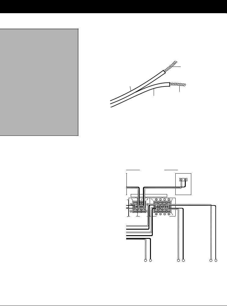
Speaker wire consists of two conductors (individual wires) encased in insulation and is usually color-coded or marked with a ridge along one side so you can identify each conductor. Use these markings as a guide to help you properly connect the speakers to your receiver.
Follow these steps to prepare the speaker wires.
Wire Strand
Conductor
Wire Strands
Conductor
1.Cut the speaker wires to the necessary length.
2.Separate the wires about 4 inches on each end.
3.Using a wire stripper, carefully strip about 3/4 inch of insulation from the end of each conductor.
4.Twist the end of each conductor to secure any loose wire strands.
Surround Left
Speakers
|
|
|
|
|
|
|
|
|
|
|
|
|
|
|
|
|
|
|
|
|
|
|
|
|
|
|
|
|
|
|
|
|
|
|
|
|
|
|
|
|
|
|
|
|
|
|
|
|
|
|
|
|
|
|
|
|
|
|
|
|
|
|
|
|
|
|
|
|
|
|
|
|
|
|
|
|
|
|
|
|
|
Center Speaker |
|
|
|
|
|
|
|
|
|
|
|
|
|
|
|
|
|
|
|
|
|
|
|
|
|
|
||||||||||||||
|
|
|
|
|
|
|
|
|
|
|
|
|
|
|
|
|
|
|
|
|
|
|
|
|
|
|||||||||||||||
Front B Speakers |
|
|
|
|
|
Left |
|
|||||||||||||||||||||||||||||||||
|
|
|
|
|
|
|
|
|
|
|
|
|||||||||||||||||||||||||||||
Front A Speakers |
|
|
|
|
|
|
|
|
|
|
|
|
|
|
|
|
|
|
Left |
|||||||||||||||||||||
|
|
|
|
|
|
|
|
|
|
|
|
|
|
|
|
|
|
|||||||||||||||||||||||
6
Preparing Your Receiver
Note: Be sure you connect the receiver’s right and left positive (+) and negative (–) terminals to the speaker’s corresponding right and left positive (+) and negative (–) terminals.
Connecting the A and B Speakers
Follow these steps to connect the right speaker to the receiver’s right FRONT SPEAKERS A terminals.
1.Press the receiver’s FRONT SPEAKERS A R (+) red lever and insert the ridged or color-coded conductor’s end into the small hole. Pull back the lever to secure the conductor.
+ R –
2.Press the receiver’s FRONT SPEAKERS A R (– ) black lever and insert the other conductor’s end into the small hole. Pull back the lever to secure the conductor.
3.Connect the ridged or color-coded conductor’s loose end to the right speaker’s positive (+) terminal.
4.Connect the remaining loose conductor to the right speaker’s negative (–) terminal.
Repeat Steps 1 through 4 to connect the left speaker to the receiver’s FRONT SPEAKERS A L terminals.
Repeat this entire process to connect a second pair of speakers to the FRONT SPEAKERS B terminals.
Connecting Surround-Sound Speakers
You can connect a pair of speakers to the receiver’s REAR SPEAKERS terminals for surround-sound programs. Follow the steps in “Connecting the A and B Speakers.”
Connecting the Center Speaker
The center speaker gives additional ambiance to surround sound. Connect the center speaker to the CENTER SPEAKER terminals. Follow the steps in “Connecting the A and B Speakers.”
Connecting Center Channel and Subwoofer Amplifiers
To increase the center channel’s output power, you can connect a power amplifier to the CENTER jack, as shown. Then connect the center channel speaker to the amplifier.
Your receiver includes a line-level subwoofer output. Connecting a subwoofer to your system dramatically extends bass response for incredible richness and depth. When you listen to surround-sound programs, a subwoofer enhances your home theater experience by realistically recreating the rumble of an earthquake, the bone-jarring percussion of a cannon, and more.
To use this output, simply connect it to an amplified subwoofer’s line-level input or to an amplifier to which you have connected a subwoofer.
RadioShack stores sell a variety of suitable subwoofers and amplifiers.
7
Preparing Your Receiver
Connecting Program Sources You can connect up to five external program sources to your receiver.
L |
|
|
|
|
|
|
|
|
|
|
|
|
|
|
|
|
L |
|
L |
|
|
|
|
|
|
|
|
|
|
L |
|
|
|
|
|
|
|
R |
R |
|
|
|
|
|
|
|
|
||
|
|
|
|
|
|
|
|
|
|
|
FM |
|
|
|
|
|
|
|
|
R |
UNBAL |
|
|
|
|
|
|
|
|
75 |
|
|
|
|
|
|
|
|
|
|
|
|
|
TO MONITOR TV |
IN |
OUT |
IN |
|
|
|
GND |
|
VIDEO OUT |
|
|
|
|
VIDEO |
|
|
AM |
|
REC |
PLAY |
|
|
|
|
|
|
|
L |
|
|
|
|
|
|
IN |
|
GND |
|
|
|
|
|
|
L |
|
|
|
|
|
|
|
|
|
|
|
|
LOOP |
R |
|
|
|
|
|
|
OUT |
|
ANTENNA |
|
|
|
|
|
|
|
R |
|
|
|
TAPE2 |
|
|
VCR |
|||
|
ANTENNA |
PHONO |
CD |
LD |
CONTROL |
||||
|
MONITOR |
/TAPE1 |
|||||||
|
L |
|
GND |
|
|
|
|
|
|
|
|
|
|
|
|
|
|
|
|
|
R |
|
|
|
|
|
|
|
|
|
|
|
|
|
|
|
|
|
L |
OUT PUT |
|
L |
|
R |
CD |
CD Player
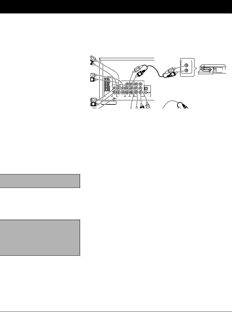
Use shielded audio cables with phono connectors for all audio connections.
Connecting a Turntable
Connect a turntable with a magnetic cartridge only. Some older turntables use a ceramic-type cartridge that does not work with this system.
Connect the turntable’s left and right cables to the receiver’s left and right PHONO jacks. Then connect the turntable’s ground wire to the receiver’s GND terminal.
Note: If you place the cassette deck directly above, below, or to the left of the receiver, the receiver could interfere with the cassette deck’s operation. If possible, position the cassette deck to the right of the receiver or locate it away from the receiver.
Connecting Cassette Deck(s)
You can connect cassette decks to the VCR/TAPE 1 and the TAPE 2 MONITOR jacks. Connect the cassette deck’s output jacks to the VCR/TAPE 1 IN (audio) or TAPE 2 PLAY jacks, and connect the input jacks of your cassette deck to VCR/ TAPE 1 OUT (audio) or TAPE 2 REC jacks.
You can connect a third cassette deck (for playback only) to the LD IN (audio) jacks.
Connecting a CD Player
To connect a CD player to the receiver, connect the CD player’s left and right output jacks to the receiver’s L and R CD input jacks.
8
Preparing Your Receiver
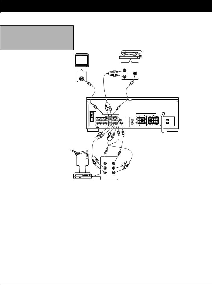
Note: If your VCR is monaural, use a Y- adapter (available at your local RadioShack store) to connect the VCR’s audio output to both the L and R audio inputs on the receiver.
Connecting Video Sources
If you connect two video sources such as VCRs or laser disc players to your receiver, you can use the receiver to switch between viewing the sources. You can also use the receiver to easily record from the video sources to the source connected to VCR/TAPE 1.
TV Monitor
VIDEO
IN
V
LD Player
AUDIO |
VIDEO |
OUT |
OUT |
L |
L |
R |
R |
|
|
|
V |
VCR
V |
|
|
|
|
|
|
V |
|
|
|
|
|
|
|
|
|
|
|
|
L |
|
|
|
|
|
|
|
|
|
|
|
|
|
R |
|
|
|
|
|
|
|
|
|
|
|
|
|
|
|
|
|
|
|
|
|
|
|
|
|
FM |
|
|
|
|
|
|
|
|
|
|
|
|
|
|
UNBAL |
|
|
|
|
|
|
|
|
|
|
|
|
|
|
75 |
|
|
|
|
|
|
|
|
|
|
|
|
|
|
|
|
|
TO MONITOR TV |
IN |
OUT |
IN |
|
|
|
|
|
|
|
|
GND |
|
|
VIDEO OUT |
|
|
|
VIDEO |
|
R |
L |
R |
L |
|
|
|
|
|
|
|
|
|
|
CENTER |
|
|
||||
AM |
|
REC |
PLAY |
|
|
|
|
PRE OUT |
|
|
A |
|
|
A |
|
|
|
|
|
|
|
|
|
|
|
||||
L |
|
|
|
|
|
|
|
IN |
|
|
|
|
|
|
GND |
|
|
|
|
|
|
L |
|
|
|
|
|
|
|
|
|
|
|
|
|
|
|
|
|
B |
|
|
B |
|
LOOP R |
|
|
|
|
|
|
|
OUT |
|
|
|
|
||
|
|
|
|
|
|
|
|
|
|
|
|
|
||
ANTENNA |
|
|
|
|
|
|
R |
|
|
|
|
R |
L |
|
|
|
TAPE2 |
|
|
|
PRE OUT |
CENTER |
|
REAR |
|
||||
|
|
|
|
|
VCR |
SPEAKER |
SPEAKERS |
FRONT SPEAKERS |
AC OUTLET |
|||||
ANTENNA |
PHONO |
MONITOR |
CD |
LD |
/TAPE1 |
CONTROL |
||||||||
|
|
|
|
|
|
|
|
SUB |
|
|
|
|
|
|
|
|
GND |
|
|
|
|
|
WOOFER |
|
|
|
|
|
|
|
|
|
|
|
|
|
V |
V |
|
|
|
|
|
|
|
|
R |
|
|
R |
|
|
|
|
|
|
|
|
|
|
|
|
|
|
L |
|
|
|
|
|
|
|
|
|
|
|
|
L |
|
|
|
|
|
|
|
|
|
|
|
V
V
|
VIDEO |
|
|
L |
IN |
OUT |
|
R |
|
|
|
|
|
|
L |
|
|
L |
R |
|
|
|
|
|
|
R |
|
VCR |
(REC) |
(PLAY) |
|
IN |
OUT |
|
|
|
|
||
Connect phono cables from a VCR’s audio outputs to the receiver’s VCR/TAPE 1 or LD IN (audio) jacks. Then connect phono cables from the receiver’s VCR/ TAPE 1 OUT (audio) jacks to the VCR’s audio input jacks.
Connect video cables from each video source’s video outputs to the receiver’s VCR/TAPE 1 or LD VIDEO IN jacks. Then connect video cables from the receiver’s VCR/TAPE 1 VIDEO OUT jack to the VCR’s video input.
Connecting a Video Monitor
The monitor (or TV with baseband video input) you connect to the VIDEO OUT terminal can monitor any program you connect to the receiver’s VCR/TAPE 1 or LD input jacks. Then connect a video cable from the receiver’s VIDEO OUT TO MONITOR TV jack to the monitor’s video input.
9
Preparing Your Receiver
Connecting the Antennas
Leg
Lead Wire
Lead Wire
|
FM |
|
|
UNBAL |
|
|
75 |
|
|
GND |
AM Loop Anten |
Ground |
AM |
|
|
|
|
|
GND |
|
|
LOOP |
|
|
ANTENNA |
|
|
AM Antenna |
|
|
|
FM |
|
|
UNBAL |
|
|
75 |
|
|
GND |
|
|
AM |
|
FM Antenna |
FM |
|
|
UNBAL |
|
|
75 |
|
|
GND |
|
|
AM |
|
|
GND |
|
|
LOOP |
|
|
ANTENNA |
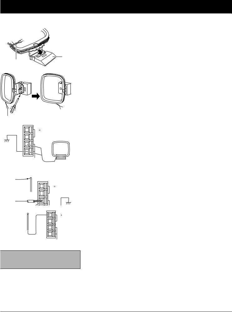
In many cities, the supplid indoor AM loop and FM antennas provide adequate reception.
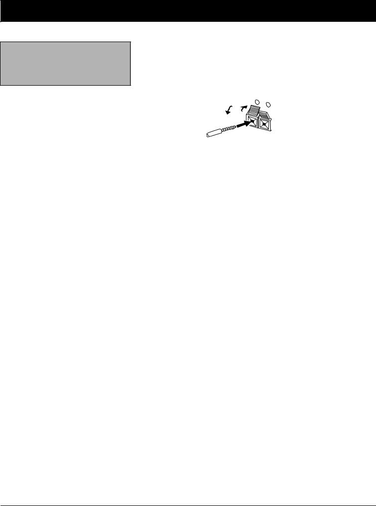
AM Antennas
Assemble the included antenna’s base by swinging the base in the direction of the arrow and inserting the antenna’s bottom tabs into the base’s slot. Then attach the antenna wires to the AM and GND terminals (bottom two terminals).
Place the antenna on a flat surface and rotate it for the best AM reception.
If the receiver is in a rack or on a shelf and there is no room for the AM loop antenna, use two screws (not supplied) to mount the base on the wall or another location as shown.
Notes:
•Keep the AM loop antenna connected even when you use another indoor antenna or an outdoor AM antenna.
•Ensure the antenna does not touch the receiver or other metal objects.
•Do not place the antenna near a CD player, a personal computer, or a TV set.
•If the wire between your AM loop antenna and receiver is too short, you can add extra wire, available at your local RadioShack store.
You can also use a RadioShack shortwave antenna kit (Cat. No. 278758), which makes an excellent outdoor AM antenna. Connect the outdoor AM antenna wire to the receiver’s AM terminal, as shown.
FM Antennas
Connect the supplied FM antenna to the FM UNBAL 75Ω terminal and extend it as shown.
Note: For the best results, use 75-ohm coaxial cable to connect an outdoor antenna to the receiver.
For better FM reception, you can also use a rabbit-ear TV antenna (for indoor use only) or an outdoor VHF TV antenna. To connect the TV antenna to the receiver, you need a VHF/UHF/FM splitter (not included). RadioShack stores carry a full line of quality outdoor antennas and antenna connection accessories.
10
 Loading...