


OPR 2001
Laser Barcode Scanner
Specifications Manual

Opticon
OPR 2001
Specifications Manual
All information subject to change without notice.
Document History
Model Number: |
OPR 2001 |
Specification Number: |
SS07011 |
|
|
|
|
Edition: |
1 |
Original Spec Number: |
SS06121 |
|
|
|
|
Date: |
2007-02-14 |
|
|
|
|
|
|
Copyright 2007 Opticon. All rights reserved.
This manual may not, in whole or in part, be copied, photocopied, reproduced, translated or converted to any electronic or machine readable form without prior written consent of Opticon.
Limited Warranty and Disclaimers
PLEASE READ THIS MANUAL CAREFULLY BEFORE INSTALLING OR USING THE PRODUCT.
Serial Number
A serial number appears on all Opticon products. This official registration number is directly related to the device purchased. Do not remove the serial number from your Opticon device. Removing the serial number voids the warranty.
Warranty
Unless otherwise agreed in a written contract, all Opticon products are warranted against defects in materials and workmanship for two years after purchase. Opticon will repair or, at its option, replace products that are defective in materials or workmanship with proper use during the warranty period. Opticon is not liable for damages caused by modifications made by a customer. In such cases, standard repair charges will apply. If a product is returned under warranty and no defect is found, standard repair charges will apply. Opticon assumes no liability for any direct, indirect, consequential or incidental damages arising out of use or inability to use both the hardware and software, even if Opticon has been informed about the possibility of such damages.
Packaging
The packing materials are recyclable. We recommend that you save all packing material to use should you need to transport your scanner or send it for service. Damage caused by improper packaging during shipment is not covered by the warranty.
Trademarks
Trademarks used are the property of their respective owners.
Opticon Inc. and Opticon Sensors Europe B.V. are wholly owned subsidiaries of OPTOELECTRONICS Co., Ltd., 5-3, Tsukagoshi 5-chome, Warabi-shi, Saitama, Japan 335-0002. TEL +81-(0) 48-446-1183; FAX +81-(0) 48-446-1180
SUPPORT
USA |
Europe |
Phone: 800-636-0090 |
|
Email: support@opticonusa.com |
Email: support@opticon.com |
Web: www.opticonusa.com |
Web: www.opticon.com |
|
|
2

|
|
|
|
Opticon |
|
|
|
|
OPR 2001 |
|
|
|
|
Specifications Manual |
Contents |
|
|||
1. |
Abstract |
.................................................................................................................................... |
7 |
|
2. |
Overview .................................................................................................................................. |
7 |
||
3. |
Physical ....................................................................................................................Features |
8 |
||
|
3.1. |
Dimensions ...................................................................................................................... |
8 |
|
|
3.2. |
Weight.............................................................................................................................. |
8 |
|
4. |
Environmental ................................................................................................Specifications |
8 |
||
|
4.1. Operating ..............................................................................Temperature and Humidity |
8 |
||
|
4.2. Storage .................................................................................Temperature and Humidity |
8 |
||
|
4.3. |
Ambient ...................................................................................................Light Immunity |
9 |
|
5. |
Electrical .......................................................................................................Specifications |
10 |
||
|
5.1. |
RS- ........................................................................................................................232C |
10 |
|
|
5.2. |
USB, ..................................................................................................................Wedge |
10 |
|
6. |
Optical Specifications........................................................................................................... |
11 |
||
|
6.1. |
Laser .......................................................................................Scanning Specifications |
11 |
|
|
6.2. |
Laser ..............................................................................................Scanning Standard |
11 |
|
|
6.2.1. ................................................................................................................ |
Laser Scanning Tilt |
11 |
|
|
6.2.2. ............................................................................................................... |
Scanning Curvature |
11 |
|
7. |
Technical ......................................................................................................Specifications |
12 |
||
|
7.1. Print ...........................................................................................Contrast Signal (PCS) |
12 |
||
|
7.2. Scan .............................................................................................Area and Resolution |
13 |
||
|
7.3. Pitch, ......................................................................................................Skew, and Tilt |
14 |
||
|
7.3.1. ............................................................................................................................. |
Pitch Angle |
14 |
|
|
7.3.2. ..................................................................................................Skew Angle and Dead Zone |
15 |
||
|
7.3.3. ................................................................................................................................ |
Tilt Angle |
16 |
|
|
7.4. |
Curvature ....................................................................................................................... |
17 |
|
8. |
Interface ........................................................................................................Specifications |
18 |
||
|
8.1. |
RS- .........................................................................................................232C Interface |
18 |
|
|
8.1.1. ................................................................................................. |
Settings and Communication |
18 |
|
|
8.1.2. ............................................................................................................................ |
Signal Level |
18 |
|
|
8.1.3. ...................................................................................................................... |
Pin Assignment |
19 |
|
|
8.1.4. ...................................................................................................................... |
Interface Circuit |
19 |
|
|
8.1.5. ................................................................................................................... |
Character Format |
20 |
|
|
8.1.6. .......................................................................................................... |
Communication Format |
20 |
|
3

|
|
|
|
Opticon |
|
|
|
|
OPR 2001 |
|
|
|
|
Specifications Manual |
|
8.1.7. |
Handshaking .......................................................................................................................... |
20 |
|
|
8.2. |
USB Interface Specifications ......................................................................................... |
25 |
|
|
8.2.1. |
Settings .................................................................................................................................. |
25 |
|
|
8.2.2. |
Connectors............................................................................................................................. |
25 |
|
|
8.2.3. |
Interface Circuit...................................................................................................................... |
26 |
|
|
8.3. |
DOS/V Wedge Interface Specification ........................................................................... |
26 |
|
|
8.3.1. |
Settings .................................................................................................................................. |
26 |
|
|
8.3.2. |
Connectors............................................................................................................................. |
27 |
|
9. |
Cable and Connector ............................................................................................................ |
28 |
||
|
9.1. |
RS-232C Cable.............................................................................................................. |
28 |
|
|
9.2. |
USB Cable ..................................................................................................................... |
28 |
|
|
9.3. |
Wedge Cable ................................................................................................................. |
29 |
|
|
9.4. |
Connector Specification (Scanner Side)........................................................................ |
29 |
|
10. |
Default Settings..................................................................................................................... |
30 |
||
|
10.1. Barcodes........................................................................................................................ |
30 |
||
|
10.2. Default Settings 1: Readable Codes.............................................................................. |
31 |
||
|
10.3. Default Settings 2: Read Options, Trigger, Buzzer ........................................................ |
33 |
||
11. Serial Number........................................................................................................................ |
34 |
|||
12. Packaging Specifications..................................................................................................... |
34 |
|||
|
12.1. Individual Packaging Specification................................................................................. |
34 |
||
|
12.2. Collective Packaging Specification ................................................................................ |
34 |
||
13. |
Durability................................................................................................................................ |
35 |
||
|
13.1. Electrical Noise .............................................................................................................. |
35 |
||
|
13.2. Shock............................................................................................................................. |
35 |
||
|
13.2.1. Drop Test (without packaging)............................................................................................... |
35 |
||
|
13.2.2. Drop Test (with individual packaging).................................................................................... |
35 |
||
|
13.3. Vibration Strength .......................................................................................................... |
36 |
||
|
13.4. Static Electricity ............................................................................................................. |
36 |
||
|
13.5. Dust and Drip Proof ....................................................................................................... |
36 |
||
|
13.6. Cable Strength............................................................................................................... |
36 |
||
|
13.6.1. Cable Pulling Test.................................................................................................................. |
36 |
||
|
13.6.2. Cable Tail Bending Test......................................................................................................... |
36 |
||
14. |
Reliability ............................................................................................................................... |
37 |
||
15. Auto Trigger (Option)............................................................................................................ |
37 |
|||
4

|
Opticon |
|
OPR 2001 |
|
Specifications Manual |
15.1. Auto Trigger Settings ..................................................................................................... |
38 |
15.1.1. Stand Only ............................................................................................................................. |
38 |
15.1.2. Always.................................................................................................................................... |
39 |
15.1.3. Manually................................................................................................................................. |
39 |
16. Regulatory Compliance ........................................................................................................ |
40 |
16.1. Laser Safety................................................................................................................... |
40 |
16.2. Product Safety ............................................................................................................... |
40 |
16.3. EMC............................................................................................................................... |
40 |
16.4. Compliance to RoHS ..................................................................................................... |
40 |
17. Safety ..................................................................................................................................... |
41 |
17.1. Shock............................................................................................................................. |
41 |
17.2. Temperature Conditions ................................................................................................ |
41 |
17.3. Foreign Materials ........................................................................................................... |
41 |
17.4. Other.............................................................................................................................. |
41 |
18. Mechanical Drawing.............................................................................................................. |
42 |
Table of Figures |
|
Figure 1: Ambient light immunity ................................................................................................. |
9 |
Figure 2: Laser scanning tilt and curvature ............................................................................... |
11 |
Figure 3: Depth of field. ............................................................................................................. |
13 |
Figure 4: Pitch ........................................................................................................................... |
14 |
Figure 5: Skew angle and dead zone ........................................................................................ |
15 |
Figure 6: Tilt angle ..................................................................................................................... |
16 |
Figure 7: Curvature.................................................................................................................... |
17 |
Figure 8: Interface circuit ........................................................................................................... |
19 |
Figure 9:Character format (same for both sending and receiving) ............................................ |
20 |
Figure 10: Communication format ............................................................................................. |
20 |
Figure 11: No handshaking........................................................................................................ |
20 |
Figure 12: Busy/Ready communication..................................................................................... |
21 |
Figure 13: Cannot receive command ........................................................................................ |
21 |
Figure 14: Signal timing............................................................................................................. |
22 |
Figure 15: Modem transmit data................................................................................................ |
22 |
Figure 16: ACK/NAK.................................................................................................................. |
23 |
Figure 17: ACK/NAK—No response.......................................................................................... |
24 |
Figure 18: USB "A" connector ................................................................................................... |
25 |
Figure 19: Interface circuit ......................................................................................................... |
26 |
Figure 20: DOS/V host connector.............................................................................................. |
27 |
Figure 21: DOS/V keyboard connector...................................................................................... |
27 |
Figure 22: RS-232C cable ......................................................................................................... |
28 |
Figure 23: USB cable ................................................................................................................ |
28 |
5

|
Opticon |
|
OPR 2001 |
|
Specifications Manual |
Figure 24: Wedge cable............................................................................................................. |
29 |
Figure 25: Serial number diagram ............................................................................................. |
34 |
Figure 26: Drop test................................................................................................................... |
35 |
Figure 27: Cable tail bending test.............................................................................................. |
36 |
Figure 28: Auto trigger operation ............................................................................................... |
37 |
Figure 29: Trigger options.......................................................................................................... |
38 |
Figure 30: Mechanical drawing.................................................................................................. |
42 |
6

Opticon
OPR 2001
Specifications Manual
1. Abstract
This manual provides specifications for the OPR 2001 laser barcode scanner.
2. Overview
The OPR 2001 is a handheld laser barcode scanner. The use of a short-wavelength red laser beam enhances visibility when scanning lines.
The OPR 2001 can be configured to scan both positive and negative barcodes. Scanned data is transferred via an RS-232C, USB, or Wedge interface. Auto-trigger settings are available.
The OPR 2001 complies with RoHS. Supported symbologies:
•JAN/UPC/EAN/ all add-on
•Chinese Post Matrix 2 of 5
•Codabar/NW-7, including ABC and CX
•Code 11
•Code 39: Normal Code 39 / Full ASCII Code 39 / Italian Pharmaceutical
•Code 93
•Code 128: EAN-128
•Composite Codes: UCC/EAN-128 (incl. CC-A/B/C)
•IATA
•Industrial 2of5
•Interleaved 2of5
•ISBN-ISMN-ISSN
•Korean Postal Authority code
•Matrix 2of5
•MicroPDF417
•MSI/Plessey-UK/Plessey
•PDF417
•RSS: RSS-14 (incl. CC-A/B) / RSS-Limited (incl. CC-A/B) / RSS-Expanded (incl. CC- A/B)
•S-Code
•Telepen
•Tri-Optic
7

Opticon
OPR 2001
Specifications Manual
3.Physical Features
3.1.Dimensions
W 151.0 x D 56.0 x H 30.5 mm
3.2.Weight
60 grams max. (excluding cable weight)
4.Environmental Specifications
4.1.Operating Temperature and Humidity
Temperature: -5° to +50° C Humidity: 20 to 85% RH
4.2.Storage Temperature and Humidity
Temperature: -20° to +60° C Humidity: 10 to 90% RH
8
Opticon
OPR 2001
Specifications Manual
4.3.Ambient Light Immunity
Decoding performance is guaranteed when the range of illumination on a barcode surface is between zero and the following values:
Incandescent light |
3,000 lx |
Fluorescent light |
3,000 lx |
Sunlight |
50,000 lx |
Figure 1: Ambient light immunity
Conditions
Barcode Sample: OPTOELECTRONICS Test Sample
PCS: |
0.9 |
Resolution: |
0.25 mm |
Symbology: |
9-digit Code-39 |
Quiet Zone: |
10 mm |
N/W Ratio: |
1:2.5 |
Distance: |
70 mm |
Angle: |
α = 0° β = 15° γ = 0° |
Curvature: |
= ∞ |
Power Supply Voltage: |
5.0 V |
Direct light or specular reflection light from a source should be prevented from entering the acceptance area.
9

Opticon
OPR 2001
Specifications Manual
5.Electrical Specifications
5.1. RS-232C
Parameter |
Symbol |
Min |
Typ |
Max |
Unit |
Notes |
|
|
|
|
|
|
|
Power supply voltage |
VDD |
4.5 |
6.0 |
6.5 |
V |
|
|
|
|
|
|
|
|
Operating current |
IOP |
- |
90 |
150 |
mA |
No buzzer |
|
|
|
|
|
|
|
Peak current |
IPEAK |
- |
550 |
600 |
mA |
|
|
|
|
|
|
|
|
Standby current |
IPRE |
- |
35 |
70 |
mA |
|
|
|
|
|
|
|
|
Startup time |
TD |
- |
100 |
- |
ms |
|
|
|
|
|
|
|
|
5.2. USB, Wedge
Parameter |
Symbol |
Min |
Typ |
Max |
Unit |
Notes |
|
|
|
|
|
|
|
Power supply voltage |
VDD |
4.5 |
5.0 |
5.5 |
V |
|
|
|
|
|
|
|
|
Operating current |
IOP |
- |
90 |
150 |
mA |
No buzzer |
|
|
|
|
|
|
|
Peak current |
IPEAK |
- |
450 |
500 |
mA |
|
|
|
|
|
|
|
|
Standby current |
IPRE |
- |
35 |
70 |
mA |
|
|
|
|
|
|
|
|
Startup time |
TD |
- |
100 |
- |
ms |
|
|
|
|
|
|
|
|
Conditions
•Connect 1Ω resistance to a power supply line in series and measure the current by the voltage between both ends of resistance.
•Power supply voltage is measured at a connector terminal area.
•The current value depends on the interface type and host computer to which the device is connected.
10
Opticon
OPR 2001
Specifications Manual
6.Optical Specifications
6.1. Laser Scanning Specifications
Parameter |
Specification |
Unit |
|
|
|
Light-emitting element |
Red laser diode |
- |
|
|
|
Emission wavelength |
650 ±10 (25° C) |
nm |
|
|
|
Light output |
1.0 or less |
mW |
|
|
|
Scanning method |
Bi-directional scanning |
- |
|
|
|
Scanning speed |
100 ±20 |
scans/s |
|
|
|
Scan angle |
Scan angle: 54 ±5 |
° |
|
|
|
|
Read angle: 44 (Min) |
° |
|
|
|
6.2.Laser Scanning Standard
6.2.1.Laser Scanning Tilt
Scanning tilt is the vertical difference between the ends of a laser scan line.
•Up to 0.92° in a vertical direction from the scan origin (mirror motor mirror).
•Up to 2.46 mm when measured at 150 mm from the scan origin. Measurement is done at the center of the laser scan line.
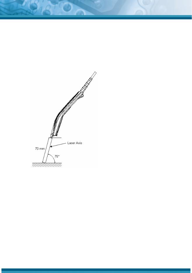
6.2.2.Scanning Curvature
Scanning curvature is the maximum difference between the laser scan line and the line between the ends of the laser scan line.
•Up to 1.17° in a vertical direction from the scan origin (mirror motor mirror).
•Up to 3.06 mm when measured at 150 mm from the scan origin. Measurement is done from the center of the laser scan line.
Figure 2: Laser scanning tilt and curvature
11

Opticon
OPR 2001
Specifications Manual
7. Technical Specifications
The conditions for technical specifications are as follows, unless otherwise specified in each section.
Conditions
Ambient temperature and humidity |
21º C / 70º F, 60% RH |
Ambient light |
500 to 900 lx |
Background |
Barcode = black |
|
Space = white |
|
Margin = white |
|
Background of label = black |
Power supply voltage |
6.0 V (RS-232C) / 5.0 V (USB, Wedge) |
Decoding test |
Approve the performance when decoding is |
|
successful in all ten tests. |
|
(Decoding is deemed successful when completed |
|
in 0.5 seconds or less.) |
7.1.Print Contrast Signal (PCS)
0.45 or higher (over 70% of reflectivity of space and quiet zone).
12

Opticon
OPR 2001
Specifications Manual
7.2.Scan Area and Resolution
The scan area is a circular area centered around the beam, which appears at various resolutions.
Figure 3: Depth of field.
Resolution |
Symbology |
PCS |
Quiet Zone |
Digits |
Depth of Field (mm) |
|
|
|
|
|
|
1.0 mm |
CODE-39 |
0.9 |
25 mm |
1 |
40 to 500 |
|
|
|
|
|
|
0.5 mm |
CODE-39 |
0.9 |
18 mm |
3 |
20 to 350 |
|
|
|
|
|
|
0.25 mm |
CODE-39 |
0.9 |
10 mm |
8 |
20 to 200 |
|
|
|
|
|
|
0.15 mm |
CODE-39 |
0.9 |
7 mm |
10 |
20 to 100 |
|
|
|
|
|
|
0.127 mm |
CODE-39 |
0.9 |
5 mm |
4 |
30 to 70 |
|
|
|
|
|
|
Conditions
Barcode Sample: OPTOELECTRONICS Test Sample
N/W Ratio: |
1:2.5 |
Angle: |
α = 0°, β = 15°, γ = 0° |
Curvature: |
R = ∞ |
13
 Loading...