


No. 59-1365-4 0902-05
INSTALLATION MANUAL
PHOTOELECTRIC DETECTOR
AX-250PLUS, AX-500PLUS AX-350TF, AX-650TF
<STANDARD >
<4 SELECTABLE BEAM FREQUENCIES >
Please read intsructions completely before beginning installation.
Photoelectric detectors detect intruders when both the upper and lower invisible infrared beams are simultaneously broken.
Maximum detection range between Transmitter and Receiver for the AX-250PLUS is 250ft. (75m), the AX-500PLUS is 500ft. (150m) and for the AX-350TF is 350ft. (100m), the AX-650TF is 650ft. (200m)
FEATURES
• Beam interruption time adjustment |
: This function allows you to select the suitable beam interruption time for any environment. |
• Anti-Frost Structure |
: Prevents fog and condensation from blocking the beams. |
• Alignment level monitor jack |
: Can easily obtain maximum optical alignment by checking the voltage from this jack. |
• Form C relay |
: Form C relay for more applications. |
• Tamper |
: N.C., Opens when cover is removed. |
• Option |
: Heating unit (HU-1), Back cover (BC-1) AX-Beam Tower (AX-BT) |
• UL Listed |
: For UL Listed applications, the heating unit (HU-1) shall not be installed with the models AX-350TF and AX-650TF. |
AX-350TF, AX-650TF ONLY
• LED indicator for fine beam alignment level |
: The optical alignment level can be checked at the Reciver. |
• Selectable beam frequencies |
: Crosstalk is eliminated with 4, channel selectable, beam frequencies. Used when stacking beams |
|
or for long range applications. |
• Re-Transmit Circuit |
: The advantage of this method is the elimination of wiring, from a detector or switch, back to the |
|
control panel. |
• D.Q.Circuit (Environmental Disqualification) |
: The environmental compensation circuit is designed to eliminate false alarms caused by snow, |
• Alarm Memory |
fog, heavy rain, ice and misalignment. |
For Safe Use of the Product
•Read this instruction manual carefully prior to installation.
•After reading, store this manual carefully in an easily accessible place for reference.
•This manual uses the following warning indications for correct use of the product and harm to you or other people and damage to your assets, which are described below. Be sure to understand the description before reading the rest of this manual.
WARNING |
Failure to follow the instructions provided with this indication and improper handling may cause death or serious injury. |
|
|
CAUTION |
Failure to follow the instructions provided with this indication and improper handling may cause injury |
and / or property damage. |
 This symbol indicates prohibition. The specific prohibited action is provided in and/or around the figuer.
 This symbol requires an action or gives an instruction.
Do not use the product for purposes other than the detection of moving objects such as people and vehicles.
Do not use the product to activate a shutter, etc., which may cause an accident.
|
Do not touch the unit base or power terminals of the product with a wet hand (do not touch when the |
WARNING |
product is wet with rain, etc.). It may cause electric shock. |
Never attempt to disassemble or repair the product. It may cause fire or damage to the devices. |
Do not exceed the voltage or current rating specified for any of the terminals during installation, doing so may cause fire or damage to the devices.
Do not pour water over the product with a bucket, hose, etc. The water may enter, which may cause damage
CAUTION
to the devices.
Clean and check the product periodically for safe use. If any problem is found, do not attempt to use the product as it is and have the product repaired by a professional engineer or electrician.
C O N T E N T S
1.PARTS IDENTIFICATION ····································· P2 |
6.BEAM INTERRUPTION |
2.PRECAUTIONS····················································· P2 |
TIME ADJUSTMENT ············································ P8 |
3.INSTALLATION METHOD ···································· P3 |
7.AX-350/650TF |
4.AX-250/500PLUS |
7-1.SELECTABLE BEAM FREQUENCIES ·········· P8 |
4-1.TERMINAL······················································ P4 |
7-2.ALARM MEMORY ·········································· P8 |
4-2.WIRING··························································· P4 |
7-3.DQ CIRCUIT ··················································· P9 |
4-3.OPTICAL ALIGNMENT ·································· P5 |
7-4.RE-TRANSMITTING CIRCUIT ······················· P9 |
5.AX-350/650TF |
8.SPECIFICATIONS··············································· P10 |
5-1.TERMINAL······················································ P6 |
9.DIMENSIONS······················································ P10 |
5-2.WIRING··························································· P6 |
10.TROUBLE SHOOTING |
5-3.OPTICAL ALIGNMENT ·································· P7 |
CHECK SHEET············································ P11,P12 |
1

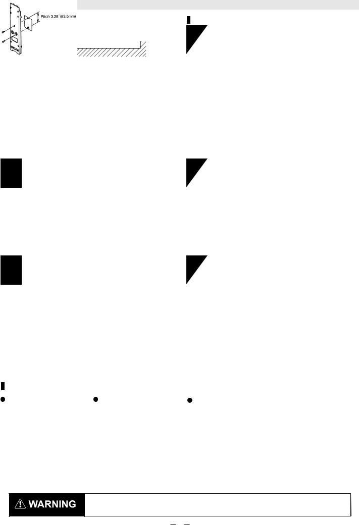
1. PARTS IDENTIFICATION
(AX-350/650TF Receiver only)
(AX-350/650TF only)
(AX-350/650TF only)
STANDARD ACCESSORIES |
|
○Screws (4×20 Self tapping)×8 |
|
○Screws (M4×30)×8 |
|
○U-Shaped brackets |
×4 |
○Beam Blocking Tool |
×2 |
2. PRECAUTIONS
1. Mount unit only on a solid surface.
2.Do not install the unit where objects moved by the wind such as plants and laundry, which may block the beam.
3.Prevent direct sunlight from entering into internal receiver.
4. A different type of beam |
5. Avoid aerial wiring. |
6. Do not install the unit |
|
should not reach the receiver. |
|
on unsteady surfaces. |
|
receiver |
transmitter |
|
|
transmitter  (other model)
7.Mount the units more than 1m away from the wall or fence.
3.3ft. (1m)
2
3. INSTALLATION METHOD
|
a. General |
b. Installation Method |
1 Detection range and installation height.
Maximum distances between Receiver and Transmitter are listed below. AX-250PLUS = 250ft (75m) Max
AX-500PLUS = 500ft (150m) Max AX-350TF = 350ft (100m) Max AX-650TF = 650ft (200m) Max
and the installation height should be at 27"~40". (0.7~1m)
2 Alignment angle
1
Lossen the cover lock screw and remove the front cover. And loosen the unit base mounting screw and remove mounting plate by sliding it down against the unit base.
2 |
well mounting Pole mounting |
Two unit installation |
|
|
(back to back) |
|
Place U-Shape brackets |
|
|
at the top of the pole. And |
|
Pull out the wire through the |
pull out the wire through the |
Fix two U-shape brackets in |
wiring hole og the Mounting |
||
wiring hole on the mounting |
plate, attach the mouting |
layers on a pole, two units |
plate and attach the plate to |
plate to the U-Shape bracket |
can be installed back to back |
the well with the screw. |
with screw. |
on a pole at the same height. |
3 Pole mounting
*Pole size should be as follews: 1 3/8"~1 7/8" O.D (Ф34~Ф48mm) (Standard U.S. 1 1/4" or 1 1/2" pipe.)
*The length of the wiring cable out of the pole should be within 20 inches (60cm).
* Face transmitter and receiver towards each other when pole mounting.
3
* C o n n e c t w i r e t o t h e t e r m i n a l s (See Sec. 4-1, 5-1 "Terminal").
*After checking optical alignment and operation check (See Sec. 4 -3, 5-3 OPTICAL ALIGNMENT), replace the cover, and fasten the lock screw tightly.
NOTE
Pole Mount Back Cover |
Electric Box Mounting |
Conduit Installtion |
For connections to single gang electric boxes, follow intructions for wall mounting.
Conduit can be installed directly into the bottom of the unit by removihg the knockout on the bottom of the cover.
1.Maximum torque requires to tighten the conduit shall not exceed 150 lb-in.
2.The conduit shall be bended before installing into the detector unit.
3.Excessive pulling of the conduit downward may cause slight cracking to the plastic conduit fitting.
3
4. AX-250/500PLUS
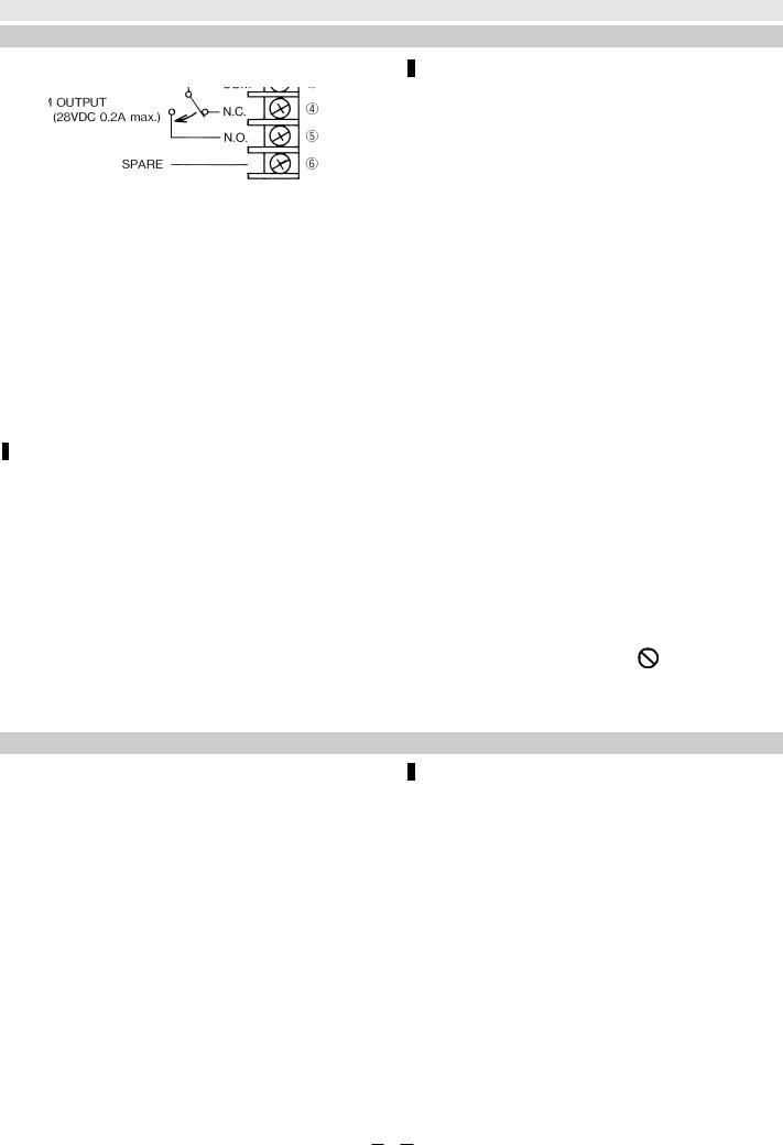
4-1. TERMINAL
|
Receiver |
Transmitter |
Wiring Distance
 When using two or more units on one wire, the maximum length is obtained by dividing the wire length listed below by the number of units used.
 Power wires should not exceed the following length.
|
MODEL |
|
AX-250/500PLUS |
|
|
Do not exceed the voltage |
|
|
|
|
|
|
|
|
|
|
WIRE SIZE |
12V DC |
|
24V DC |
|
|
or current rating specified |
|
|
|
|
|
|
|
for any of the terminals |
|
AWG22 (0.33mm2) |
1300' (400m) |
|
7500' (2300m) |
|
|
|
|
|
|
|
|
|
|
during installation, |
|
AWG20 (0.52mm2) |
2000' (600m) |
|
12000' (3600m) |
|
WARNING |
doing so might cause fire |
|
AWG18 (0.83mm2) |
3300' (1000m) |
|
19000' (5800m) |
|
|
or damage to the devices. |
|
|
|
|
|
|||
|
|
|
|
|
|
|
|
|
AWG16 (1.31mm2) |
5000' (1500m) |
|
30000' (9200m) |
|
|
|
UL requires AX-250PLUS/500PLUS to be connected to a UL listed power supply capable of providing a |
|
|
|
||||
norminal input of 12VDC, (10.5~30VDC) 50mA and battery standby time of 4 hours. |
|
|
|||||
4-2. WIRING |
|
|
|
|
|
|
|
|
1 Set |
|
|
2 Set in the line |
|
|
|
|
|
|
|
|
|||
4
 Loading...