


4A• 1
Chapter 4 Part A:
Fuel and exhaust systems - carburettor models
Contents |
|
Accelerator pump - testing, removal and refitting . . . . . . . . . . . . . . |
.18 |
Air cleaner inlet air temperature control - description and testing . . . |
.4 |
Air cleaner - removal and refitting . . . . . . . . . . . . . . . . . . . . . . . . . . . |
.3 |
Automatic choke unit - removal, refitting and adjustment . . . . . . . . . |
19 |
Automatic choke vacuum pull-down units - removal, refitting and |
|
adjustment . . . . . . . . . . . . . . . . . . . . . . . . . . . . . . . . . . . . . . . . . . . |
20 |
Carburettor - general . . . . . . . . . . . . . . . . . . . . . . . . . . . . . . . . . . . . . |
12 |
Carburettor - removal, overhaul and refitting . . . . . . . . . . . . . . . . . . . |
13 |
Carburettor filter - removal and refitting . . . . . . . . . . . . . . . . . . . . . . . |
21 |
Fuel level sender unit - removal and refitting . . . . . . . . . . . . . . . . . . . |
.8 |
Fuel pump - removal and refitting . . . . . . . . . . . . . . . . . . . . . . . . . . . |
.6 |
Fuel pump - testing . . . . . . . . . . . . . . . . . . . . . . . . . . . . . . . . . . . . . . |
.5 |
Fuel system - precautions . . . . . . . . . . . . . . . . . . . . . . . . . . . . . . . . . |
.2 |
Fuel tank - removal, examination and refitting . . . . . . . . . . . . . . . . . . |
.7 |
Fuel vapour separator (1.6 and 1.8 litre models) - removal and |
|
refitting . . . . . . . . . . . . . . . . . . . . . . . . . . . . . . . . . . . . . . . . . . . . . . |
.9 |
General description . . . . . . . . . . . . . . . . . . . . . . . . . . . . . . . . . . |
. . . . .1 |
Idle cut-off solenoid (1.8 litre models) - description and testing |
. . . .25 |
Idle speed and mixture - adjustment . . . . . . . . . . . . . . . . . . . . . |
. . . .14 |
Idle speed increase valve - testing . . . . . . . . . . . . . . . . . . . . . . . |
. . . .24 |
Inlet manifold - removal and refitting . . . . . . . . . . . . . . . . . . . . . |
. . . .26 |
Needle valve and float - removal, inspection and refitting . . . . . |
. . . .15 |
Power valve diaphragm - removal and refitting . . . . . . . . . . . . . |
. . . .17 |
Secondary throttle valve vacuum diaphragm - testing, removal and |
|
refitting . . . . . . . . . . . . . . . . . . . . . . . . . . . . . . . . . . . . . . . . . . |
. . . .16 |
Throttle cable - removal, refitting and adjustment . . . . . . . . . . . |
. . . .11 |
Throttle pedal - removal and refitting . . . . . . . . . . . . . . . . . . . . . |
. . . .10 |
Throttle position sensor (automatic transmission models) - removal |
|
and refitting . . . . . . . . . . . . . . . . . . . . . . . . . . . . . . . . . . . . . . . |
. . . .23 |
Throttle valve dashpot (automatic transmission models) - |
|
adjustment . . . . . . . . . . . . . . . . . . . . . . . . . . . . . . . . . . . . . . . |
. . . .22 |
Degrees of difficulty
Easy, suitable for |
1 |
|
|
|
|
|
|
|
|
|
|
|
|
||
novice with little |
|
|
|
|
|
|
|
experience |
|
|
|
|
|
|
|
|
|
|
|
|
|
|
4A |
Specifications |
|
|
|
|
|||
|
|
|
|
|
|||
General |
|
|
|
|
|
|
|
Fuel tank capacity . . . . . |
. . . . |
. . . . . . . . . . . . . . . . . . . . . . . |
. . . . . . . . . . 61.0 litres |
|
|
|
|
Fuel octane rating: |
|
|
98 RON (4-star) |
|
|
|
|
Leaded . . . . . . . . . . . |
. . . . |
. . . . . . . . . . . . . . . . . . . . . . . |
|
|
|
||
Unleaded . . . . . . . . . |
. . . . |
. . . . . . . . . . . . . . . . . . . . . . . |
. . . . . . . . . . 95 RON (Premium) |
|
|
|
|
Carburettor type (all models) . . . . . . . . . . . . . . . . . . . . . . . |
. . . . . . . . . . Pierburg 2E3 |
|
|
|
|||
Air cleaner element |
|
|
|
|
|
||
Application: |
|
|
Champion W103 |
|
|
|
|
Round type . . . . . . . . |
. . . . |
. . . . . . . . . . . . . . . . . . . . . . . |
|
|
|
||
Square type . . . . . . . . |
. . . . |
. . . . . . . . . . . . . . . . . . . . . . . |
. . . . . . . . . . Champion U512 |
|
|
|
|
14 NV engine |
|
|
|
|
|
|
|
Idle speed . . . . . . . . . . . |
. . . . |
. . . . . . . . . . . . . . . . . . . . . . . |
. . . . . . . . . . 925 ± 25 rpm |
|
|
|
|
Idle mixture (CO content) . . . . . . . . . . . . . . . . . . . . . . . . . . |
. . . . . . . . . . 0.5 to 1.5% |
|
|
|
|||
Fast idle speed . . . . . . . |
. . . . |
. . . . . . . . . . . . . . . . . . . . . . . |
. . . . . . . . . . 2200 to 2600 rpm |
|
|
|
|
Choke valve gap . . . . . . |
. . . . |
. . . . . . . . . . . . . . . . . . . . . . . |
. . . . . . . . . . 1.5 to 3.5 mm |
|
|
|
|
Choke pull-down gap: |
|
|
1.7 to 2.1 mm |
|
|
|
|
“Small” . . . . . . . . . . . |
. . . . |
. . . . . . . . . . . . . . . . . . . . . . . |
|
|
|
||
“Large” . . . . . . . . . . . |
. . . . |
. . . . . . . . . . . . . . . . . . . . . . . |
. . . . . . . . . . 2.5 to 2.9 mm |
|
|
|
|
Idle fuel jet . . . . . . . . . . |
. . . . |
. . . . . . . . . . . . . . . . . . . . . . . |
45. . . . . . . . . . |
|
|
|
|
Idle air bleed . . . . . . . . . |
. . . . |
. . . . . . . . . . . . . . . . . . . . . . . |
130. . . . . . . . . . |
|
Secondary |
||
Venturi diameter |
|
|
Primary |
||||
. . . . |
. . . . . . . . . . . . . . . . . . . . . . . |
. . . . . . . . . . 20.0 mm |
24.0 mm |
||||
Main jet . . . . . . . . . . . . . |
. . . . |
. . . . . . . . . . . . . . . . . . . . . . . |
. . . . . . . . . . X95 |
X110 |
|||

4A• 2 Fuel and exhaust systems - carburettor models
16 SV engine
Idle speed |
925 ± 25 rpm |
|
Manual transmission . . . . . . . . . . . . . . . . . . . . . . . . . . . . . . . . . . . . . . |
|
|
Automatic transmission . . . . . . . . . . . . . . . . . . . . . . . . . . . . . . . . . . . |
825 ± 25 rpm (in ‘park’ or ‘neutral’) |
|
Idle mixture (CO content) . . . . . . . . . . . . . . . . . . . . . . . . . . . . . . . . . . . . |
0.5 to 1.5% |
|
Fast idle speed . . . . . . . . . . . . . . . . . . . . . . . . . . . . . . . . . . . . . . . . . . . . |
2000 to 2400 rpm |
|
Choke valve gap . . . . . . . . . . . . . . . . . . . . . . . . . . . . . . . . . . . . . . . . . . . |
1.5 to 3.5 mm |
|
Choke pull-down gap: |
|
|
Up to 1990: |
1.3 to 1.7 mm |
|
“Small” . . . . . . . . . . . . . . . . . . . . . . . . . . . . . . . . . . . . . . . . . . . . . . . . |
|
|
“Large” . . . . . . . . . . . . . . . . . . . . . . . . . . . . . . . . . . . . . . . . . . . . . . . . |
1.9 to 2.3 mm |
|
From 1990: |
1.5 to 1.7 mm |
|
“Small” . . . . . . . . . . . . . . . . . . . . . . . . . . . . . . . . . . . . . . . . . . . . . . . . |
|
|
“Large” . . . . . . . . . . . . . . . . . . . . . . . . . . . . . . . . . . . . . . . . . . . . . . . . |
2.0 to 2.2 mm |
|
Idle fuel jet . . . . . . . . . . . . . . . . . . . . . . . . . . . . . . . . . . . . . . . . . . . . . . . |
45 |
|
Idle air bleed . . . . . . . . . . . . . . . . . . . . . . . . . . . . . . . . . . . . . . . . . . . . . . |
132.5 |
Secondary |
Venturi diameter |
Primary |
|
20.0 mm |
24.0 mm |
|
Main jet: |
X95 |
X105 |
Up to 1990 . . . . . . . . . . . . . . . . . . . . . . . . . . . . . . . . . . . . . . . . . . . . . |
||
From 1990 . . . . . . . . . . . . . . . . . . . . . . . . . . . . . . . . . . . . . . . . . . . . . . |
X92.5 |
X105 |
18 SV engine
Idle speed . . . . . . . . . . . . . . . . . . . . . . . . . . . . . . . . . . . . . . . . . . . . . . . . |
925 ± 25 rpm |
|
Idle mixture (CO content) . . . . . . . . . . . . . . . . . . . . . . . . . . . . . . . . . . . . |
0.5 to 1.5% |
|
Fast idle speed . . . . . . . . . . . . . . . . . . . . . . . . . . . . . . . . . . . . . . . . . . . . |
1900 to 2300 rpm |
|
Choke valve gap . . . . . . . . . . . . . . . . . . . . . . . . . . . . . . . . . . . . . . . . . . . |
1.5 to 3.5 mm |
|
Choke pull-down gap: |
2.2 ± 0.2 mm |
|
“Small” . . . . . . . . . . . . . . . . . . . . . . . . . . . . . . . . . . . . . . . . . . . . . . . . |
|
|
“Large” . . . . . . . . . . . . . . . . . . . . . . . . . . . . . . . . . . . . . . . . . . . . . . . . |
3.3 ± 0.2 mm |
|
Idle fuel jet . . . . . . . . . . . . . . . . . . . . . . . . . . . . . . . . . . . . . . . . . . . . . . . |
42.5 |
|
Idle air bleed . . . . . . . . . . . . . . . . . . . . . . . . . . . . . . . . . . . . . . . . . . . . . . |
132.5 |
Secondary |
Main jet |
Primary |
|
107.5 |
125 |
Torque wrench settings |
Nm |
lbf ft |
|
|
|
|
|||
Exhaust manifold nuts . . . . . . . . . . . . . . . . . . . . . |
. . . . . . . . . . . . . . . . . 22 |
|
16 |
|
|
|
|
||
Exhaust downpipe-to-manifold bolts . . . . . . . . . . |
. . . . . . . . . . . . . . . . . 25 |
|
18 |
|
|
|
|
||
Exhaust fixings except flexible joint bolts . . . . . . . |
. . . . . . . . . . . . . . . . . 25 |
|
18 |
|
|
|
|
||
Exhaust flexible joint bolts . . . . . . . . . . . . . . . . . . |
. . . . . . . . . . . . . . . . . 12 |
|
9 |
|
|
|
|
||
Fuel pump bolts . . . . . . . . . . . . . . . . . . . . . . . . . . |
. . . . . . . . . . . . . . . . . 18 |
|
13 |
|
|
|
|
||
Fuel tank mounting strap bolts . . . . . . . . . . . . . . . |
. . . . . . . . . . . . . . . . . 20 |
|
15 |
|
|
|
|
||
Inlet manifold nuts . . . . . . . . . . . . . . . . . . . . . . . . |
. . . . . . . . . . . . . . . . . 22 |
|
16 |
|
|
|
|
||
|
|
The air cleaner has a wax or vacuum- |
2 When working on fuel system components, |
||||||
1 General description |
|
||||||||
|
controlled air inlet supplying a blend of hot |
scrupulous cleanliness must be observed, |
|||||||
|
|
and cold air to suit the prevailing engine |
and care must be taken not to introduce any |
||||||
|
|
operating conditions. A fuller description is |
foreign matter into fuel lines or components. |
||||||
|
|
given in Section 4. |
Carburettors |
in |
particular |
are delicate |
|||
The fuel system on all carburettor models |
|||||||||
All engines available within the Cavalier |
instruments, and care should be taken not to |
||||||||
comprises a fuel tank, a fuel pump, a vapour |
range can be operated on unleaded petrol - |
||||||||
disturb |
any |
components |
unnecessarily. |
||||||
separator (1.6 and 1.8 litre models only), a |
see Chapter 5. |
||||||||
Before |
attempting |
work on |
a carburettor, |
||||||
downdraught carburettor, and a thermostati- |
|
|
|||||||
|
|
ensure that the relevant spares are available. |
|||||||
cally-controlled air cleaner. |
2 Fuel system - precautions |
|
|||||||
|
Full overhaul procedures for carburettors have |
||||||||
The fuel tank is mounted under the rear of |
|
||||||||
the vehicle, forward of the rear suspension. |
|
|
not been given in this Chapter. Complete |
||||||
|
|
stripdown of a carburettor is unlikely to cure a |
|||||||
The tank is ventilated to the atmosphere, and |
|
|
|||||||
has a simple filler pipe and a fuel gauge |
|
|
fault that is not immediately obvious, without |
||||||
1 Certain adjustment points in the fuel system |
|||||||||
introducing new problems. If persistent |
|||||||||
sender unit. |
are protected by tamperproof caps, plugs or |
||||||||
The fuel pump is a mechanical diaphragm |
seals. In some territories, it is an offence to |
problems are met, it is recommended that the |
|||||||
type, actuated by a pushrod bearing on the |
drive a vehicle with broken or missing |
advice of a Vauxhall dealer or carburettor |
|||||||
camshaft. |
tamperproof seals. Before disturbing a |
specialist is sought. Most dealers will be able |
|||||||
The fuel vapour separator is used to |
tamperproof seal, check that no local or |
to provide carburettor re-setting and servicing |
|||||||
stabilise the fuel supply to the carburettor. |
national laws will be broken by doing so, and |
facilities, and if necessary it should be |
|||||||
Vapour is purged from the carburettor fuel |
fit a new tamperproof seal after adjustment is |
possible to buy a reconditioned carburettor. |
|||||||
supply, thus improving hot starting qualities. |
complete, where required by law. Do not |
3 Refer to Chapter 5, for precautions to be |
|||||||
The carburettor is a Pierburg 2E3 type, a full |
break tamperproof seals on a vehicle that is |
observed when working on vehicles fitted with |
|||||||
description of which is given in Section 12. |
still under warranty. |
an engine management system. |
|||||||
Fuel and exhaust systems - carburettor models 4A• 3
and which may result in
spillage. Before carrying out on the fuel system, refer to
given in the “Safety first!” the beginning of this manual them implicitly. Petrol is a
and volatile substance, necessary when
it cannot be overstressed.
7Fit a new air cleaner body-to-carburettor seal.
8Connect the crankcase ventilation hose to the stub on the underside of the body, and connect the vacuum hose for the air temperature control flap.
9Locate the body on the carburettor, and at the same time locate the inlet duct on the hot air hose on the exhaust manifold.
10Engage the crankshaft ventilation hose in the plastic clip.
11Refit the air cleaner element, referring to Chapter 1 if necessary.
4 Air cleaner inlet air |
3 |
temperature control - |
|
description and testing |
Description
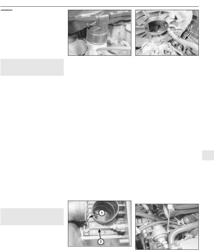
1 The air cleaner is thermostaticallycontrolled, to provide air at the most suitable temperature for combustion with minimum exhaust emission levels.
2 The optimum air temperature is achieved by drawing in cold air from an inlet at the front of the vehicle, and blending it with hot air
hot air hose
drawn from a shroud on the exhaust manifold. The proportion of hot and cold air is varied by the position of a flap valve in the air cleaner inlet spout, which is controlled by either a vacuum diaphragm or wax-type unit. The vacuum diaphragm type is regulated by a heat
sensor located within the air cleaner body
(see illustration).
Testing
3 To check the operation of the air temperature control, the engine must be cold. First check the position of the flap valve. On the vacuum type, remove the air cleaner cover and check that the flap is open to admit only cold air from outside the car. Then start the engine and check that the flap now moves to admit only hot air from the exhaust manifold. On the wax type, the flap should already be positioned to admit only hot air from the exhaust manifold.
4Temporarily refit the cover on the vacuum type.
5Run the engine until it reaches its normal operating temperature.
6On the vacuum type, remove the air cleaner cover and check that the flap is now positioned to admit only cold air from outside the car. In cold weather it should be a mixture of hot and cold air. Refit the cover after making the check. On the wax type, use a mirror to check that the flap is positioned in the same way as given for the vacuum type.
7If the flap does not function correctly, the air cleaner casing must be renewed. Note that the vacuum type thermostat can be renewed separately if necessary.
4.2 |
Air cleaner flap valve operating |
1 |
mechanism |
Flap valve 2 Operating rod |
ventilation hose (arrowed)
5 Fuel pump - testing |
2 |
|
|
|
|
Note: Refer to Section 2 before proceeding
1Disconnect the ignition coil LT lead.
2Place a clean piece of rag under the pump outlet, then disconnect the pump outlet hose. Be prepared for fuel spillage, and take adequate fire precautions.
3Have an assistant crank the engine on the starter. Well-defined spurts of fuel must be ejected from the pump outlet - if not, the pump is probably faulty (or the tank is empty). Dispose of the fuel-soaked rag safely.
4No spare parts are available for the pump, and if faulty, the unit must be renewed.
6 Fuel pump - removal and |
3 |
|
refitting |
|
|
|
4A |
|
Note: Refer to Section 2 before proceeding |
||
Removal
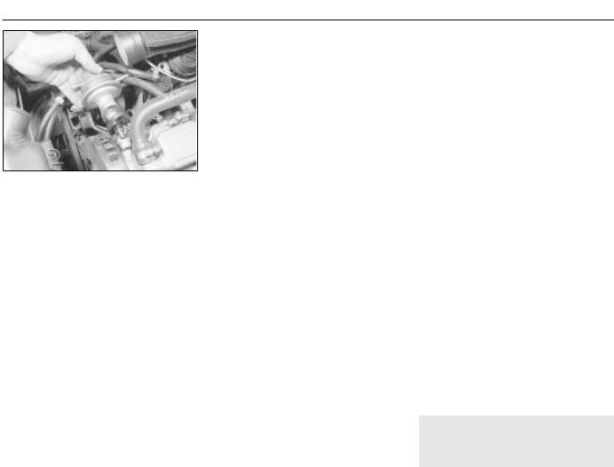
1The fuel pump is located at the rear righthand end of the camshaft housing.
2Disconnect the battery negative lead.
3Disconnect the fuel hoses from the pump (see illustration). If necessary, label the
hoses so that they can be reconnected to their correct locations. Be prepared for fuel spillage, and take adequate fire precautions. Plug the open ends of the hoses to prevent dirt ingress and further fuel spillage.
fuel pump - 1.6 litre model
4A• 4 Fuel and exhaust systems - carburettor models
6.4Withdrawing the fuel pump and plastic insulating block - 1.6 litre model
4 Unscrew the two securing bolts, and
withdraw the pump from the camshaft housing (see illustration).
5 Recover the plastic insulating block.
Refitting
6Refitting is a reversal of removal, but ensure that the fuel hoses are reconnected to their correct locations as noted during removal, and tighten the securing bolts to the specified torque.
7Run the engine and check for leaks on completion. If leakage is evident, stop the engine immediately and rectify the problem without delay. Note that the engine may take a longer time than usual to start when the pump has been removed, as the pump refills with fuel.
7 Fuel tank - removal, |
4 |
examination and refitting |
|
|
|
Note: Refer to Section 2 before proceeding
Removal
1Disconnect the battery negative lead.
2Siphon out any remaining fuel in the tank through the filler pipe. Siphon the fuel into a clean metal container that can be sealed.
3Chock the front wheels, then jack up the
rear of the vehicle, and support securely on axle stands (see “ Jacking and Vehicle Support” ) placed under the body side
members.
4 Disconnect the exhaust system front flexible joint. Suspend the front section of the exhaust system with wire or string from the underbody.
5Disconnect the rear section of the exhaust system from its rubber mountings, and allow it to rest on the rear suspension torsion beam. It is advisable to support the rear section of the exhaust at its front end, with wire or string from the underbody, to avoid straining the system.
6Unclip the handbrake cable from the bracket on the left-hand fuel tank securing strap.
7Disconnect the fuel hoses from the fuel level sender unit located in the right-hand side of the fuel tank. Make a note of the hose
positions for use when refitting. Be prepared for fuel spillage, and take adequate fire precautions. Plug the open ends of the hoses, to prevent dirt ingress and further fuel loss.
8 Disconnect the wiring plug from the fuel level sender unit.
9Disconnect the filler and vent hoses from the rear of the fuel tank.
10Support the weight of the fuel tank on a jack with an interposed block of wood.
11Unscrew the securing bolts from the tank mounting straps, then remove the straps and
lower the tank sufficiently to enable the remaining vent hose.
assistant, withdraw the right-hand side of the vehicle. Note that as the tank is withdrawn,
some residual fuel may be released.
Examination
13If the tank contains sediment or water, it may be cleaned out using two or three rinses with clean fuel. Shake vigorously using several changes of fuel, but before doing so, remove the fuel level sender unit, as described in Section 8. This procedure should be carried out in a well-ventilated area, and it is vital to take adequate fire precautions - refer to the “ Safety first!” Section at the beginning of this manual for further details.
14Any repairs to the fuel tank should be carried out by a professional. Do not under any circumstances attempt to weld or solder a fuel tank. Removal of all residual fuel vapour requires several hours of specialist cleaning.
Refitting
15Refitting is a reversal of removal, ensuring that all hoses are reconnected to their correct locations as noted during removal.
16On completion, fill the fuel tank, then run the engine and check for leaks. If leakage is evident, stop the engine immediately and rectify the problem without delay. Note that the engine may take a longer time than usual to start when the fuel tank has been removed, as the pump refills with fuel.
8 Fuel level sender unit - |
3 |
removal and refitting |
|
|
|
Note: Refer to Section 2 before proceeding
Removal
1Disconnect the battery negative lead.
2Siphon out any remaining fuel in the tank through the filler pipe. Siphon the fuel into a clear metal container that can be sealed.
3Chock the front wheels, then jack up the rear
of the vehicle, and support securely on axle stands (see “ Jacking and Vehicle Support”)
placed under the body side members.
4The sender unit is located in the right-hand side at the fuel tank.
5Make alignment marks on the sender unit and the fuel tank, so that the sender unit can be refitted in its original position.
6Disconnect the fuel hoses from the sender unit. Be prepared for fuel spillage, and take adequate fire precautions. Plug the open ends of the hoses, to prevent dirt ingress and further fuel loss.
7Disconnect the wiring plug from the fuel level sender unit.
8To remove the sender unit, engage a flat piece of metal as a lever between two of the slots on the sender unit rim, and turn it anticlockwise.
9Withdraw the unit carefully, to avoid bending the float arm.
10Recover the sealing ring.
Refitting
11 Refitting is a reversal of removal, remembering the following points.
12Examine the condition of the sealing ring, and renew if necessary.
13Ensure that the marks made on the sender unit and fuel tank before removal are aligned.
14Ensure that the hoses are reconnected to their correct locations as noted during removal.
15On completion, fill the fuel tank, then run the engine and check for leaks. Also check that the fuel gauge reads correctly. If leakage is evident, stop the engine immediately and rectify the problem without delay. Note that the engine may take a longer time than usual to start when the sender unit has been removed, as the fuel pump refills with fuel.
9 Fuel vapour separator (1.6 |
3 |
and 1.8 litre models) - |
|
removal and refitting |
Note: Refer to Section 2 before proceeding
Removal
1The fuel vapour separator is located on a bracket attached to the side of the carburettor.
2Note the locations of the three fuel hoses, labelling them if necessary for use when refitting, then disconnect the hoses from the vapour separator. Be prepared for fuel spillage, and take adequate fire precautions. Plug the open ends of the hoses, to prevent dirt ingress and further fuel spillage.
3Remove the two securing screws, and lift the vapour separator from its bracket.
4Check the body of the separator for cracks or leaks before refitting, and renew if necessary.
Refitting
5Refitting is a reversal of removal, but ensure that the three fuel hoses are connected to their correct locations as noted during removal.
6Run the engine and check the hose connections for leaks on completion. If leakage is evident, stop the engine immediately and rectify the problem without delay.
Fuel and exhaust systems - carburettor models 4A• 5
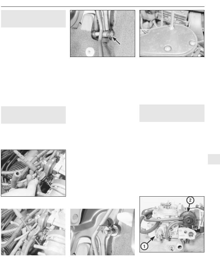
11.2A Extract the throttle cable end clip . . .
arrowed
box. Extract the three securing screws and lift
off the air box, complete with air trunking (see illustration).
2Extract the clip from the cable end fitting at
the bracket on the carburettor, then slide the cable end grommet from the bracket (see illustrations).
3Slide the cable end from the throttle valve lever on the carburettor.
4Working inside the vehicle, remove the lower trim panel from the driver’s footwell.
5Slide the cable retainer from the bracket on the top of the pedal, and disconnect the cable end from the pedal.
6Make a careful note of the cable routing, then withdraw the cable through the bulkhead into the engine compartment.
Refitting
7 Refitting is a reversal of removal, remembering the following points.
8Ensure that the cable is correctly routed, as noted before removal.
9Ensure that the bulkhead grommet is correctly seated in its hole.
Adjustment
10 On completion, check the throttle mechanism for satisfactory operation, and if necessary adjust the cable, as described in the following paragraphs.
11 Two points of cable adjustment are provided. A stop screw is located on the
pedal arm to control the fully released position of the pedal stop (see illustration). A clip is
11.1 Removing an air box securing screw
12 The cable should be adjusted so that when the throttle pedal is released, there is very slight free play in the cable at the carburettor end.
13 Check that when the throttle pedal is fully depressed, the throttle valve is fully open. Adjust the position of the clip on the cable sheath, and the pedal stop screw, to achieve the desired results.
12 Carburettor - general
1 The Pierburg 2E3 carburettor is of twinventuri, fixed-jet sequential throttle type. The primary throttle valve operates alone except at high engine speeds and loads, when the secondary throttle valve is operated, until at full-throttle, both are fully open. This arrangement allows good fuel economy during light acceleration and cruising, but also gives maximum power at full-throttle. The
secondary throttle valve is vacuum-operated, 4A according to the vacuum produced in the primary venturi. The primary throttle barrel
and venturi diameters are smaller than their secondary counterparts. The carburettor is a complicated instrument, with various refinements and sub-systems added to
achieve improved driveability, economy and exhaust emission levels (see illustrations).
|
|
|
12.1A Side view of carburettor, showing |
|
11.2B . . .and slide the grommet from the |
11.11 Throttle pedal stop screw |
|||
accelerator pump (1) and main choke pull- |
||||
bracket |
|
down diaphragm unit (2) |
||
4A• 6 Fuel and exhaust systems - carburettor models
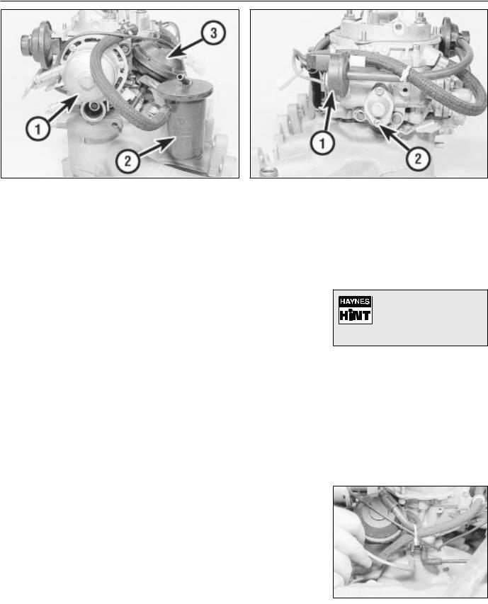
12.1B Side view of carburettor, showing automatic choke housing (1), vapour separator (2) and secondary throttle valve vacuum diaphragm (3)
12.1C Side view of carburettor, showing secondary choke pulldown solenoid (1) and power valve (2)
2 A separate idle system operates independently from the main jet system, supplying fuel by way of the mixture control screw.
3The main jets are calibrated to suit engine requirements at mid-range throttle openings. To provide the necessary fuel enrichment at full throttle, a vacuum-operated power valve is used. The valve provides extra fuel under the low vacuum conditions associated with wide throttle openings.
4To provide an enriched mixture during acceleration, an accelerator pump delivers extra fuel to the primary main venturi. The accelerator pump is operated mechanically by a cam on the throttle linkage.
5A fully automatic choke is fitted, operated by a coolant and electrically heated bi-metal coil. When the engine is cold, the bi-metal coil is fully wound up, holding the choke plate (fitted to the primary barrel) closed. As the engine warms up, the bi-metal coil is heated and therefore unwinds, progressively opening the choke plate. A vacuum operated pulldown system is employed, whereby, if the engine is under choke but is only cruising (i.e. not under heavy load) the choke plate is opened against the action of the bi-metal coil. The pull-down system prevents an over-rich mixture, which reduces fuel economy and may cause unnecessary engine wear when the engine is cold. A secondary pull-down solenoid is fitted, which operates in conjunction with the main diaphragm unit to modify the pull-down characteristics, improving fuel economy.
61.8 litre models are fitted with an idle cut-off solenoid. This is an electrically operated valve, which interrupts the idle mixture circuit when the ignition is switched off, this preventing engine “run-on”.
13 Carburettor - removal, |
3 |
overhaul and refitting |
|
|
|
Note: Refer to Section 2 before proceeding. New gasket(s) must be used when refitting the carburettor. A tachometer and an exhaust gas analyser will be required to check the idle speed and mixture on completion
Removal
1Disconnect the battery negative lead.
2Remove the air cleaner, on early models. On later models, disconnect the air trunking from the air cleaner, then disconnect the vacuum pipe and breather hose from the air box. Extract the three securing screws and lift off the air box, complete with air trunking.
3On 1.4 litre models, disconnect the fuel supply hose from the carburettor, and on 1.6 and 1.8 litre models, disconnect the fuel supply and return hoses from the vapour separator. Be prepared for fuel spillage, and take adequate fire precautions. Plug the ends of the hoses, to prevent dirt ingress and further fuel spillage.
4Extract the clip from the throttle cable end fitting at the bracket on the carburettor, then slide the cable end grommet from the bracket, and slide the cable end from the throttle valve lever.
5Disconnect the coolant hoses from the automatic choke housing noting their locations, as an aid to refitting. Be prepared for coolant spillage, and plug the hoses, or secure them with their ends facing upwards, to prevent further coolant loss.
6Disconnect the vacuum pipes from the front
of the carburettor, noting their locations and routing for use when refitting (see illustration).
7Disconnect the choke heater wire and any additional wiring.
8 Unscrew the three securing nuts, and withdraw the carburettor from the inlet manifold studs.
9 Recover the gasket(s) and insulator block that fit between the carburettor and the inlet manifold.
Overhaul
Aerosol cans of carburettor |
cleaner are widely available |
and can prove useful in |
helping to clean internal |
passages of stubborn obstructions. |
10With the carburettor removed from the vehicle, drain the fuel from the float chamber and vapour separator (where applicable). Clean the outside of the carburettor, then remove the top cover (Section 15).
11Blow through the jets and drillings with compressed air, or air from a foot pump - do not probe them with wire. If it is wished to remove the jets, unscrew them carefully with well-fitting tools.
12Remove the fuel filter gauze from the inlet union, refer to Section 21, for details. Vauxhall recommend that it is renewed whenever the carburettor is cleaned.
pipe from the carburettor - 1.6 litre model
Fuel and exhaust systems - carburettor models 4A• 7
13Clean any foreign matter from the float chamber. Renew the float, the float needle valve and seat if wear is evident, or if the float is punctured or otherwise damaged. Check that the needle valve closes completely before the float reaches the top of its movement. See Section 15, for details of float level checking.
14Renew the diaphragms in the part-load enrichment valve and in the accelerator pump. If additional pump or valve parts are supplied in the overhaul kit, renew these parts also.
15Further dismantling is not recommended. Pay particular attention to the throttle opening mechanism arrangement if it is decided to dismantle it; the interlocking arrangement is important.
16Reassemble in the reverse order to dismantling. Use new gaskets and seals throughout; lubricate linkages with a smear of molybdenum based grease.
Refitting
17Carry out the following procedure before refitting.
a)Position the fast idle adjustment screw on the highest step of the fast idle cam.
b)Use a gauge rod or twist drill of the specified diameter to measure the opening of the primary throttle valve.
c)Adjust if necessary at the fast idle adjustment screw.
d)Note that this is a preliminary adjustment; final adjustment of the fast idle speed should take place with the engine running.
18Refitting is a reversal of removal, but renew the gasket(s).
19After refitting, carry out the following checks and adjustments.
20Check the throttle cable free play and adjust if necessary, as described in Section 11.
21Check and if necessary top-up the coolant level, as described in Chapter 3.
22Check and if necessary adjust the idle speed and mixture, as described in Section 14.
14 Idle speed and mixture - |
3 |
adjustment |
|
|
|
Note: Refer to Section 2 before proceeding. To carry out the adjustments, an accurate tachometer and an exhaust gas analyser (CO meter) will be required
1 To check the idle speed and mixture adjustment, the following conditions must be met:
a)The engine must be at normal operating temperature
b)All electrical consumers (cooling fan, heater blower, headlamps, etc.) must be switched off
c)The ignition timing and spark plug gaps must be correctly adjusted - see Chapters 1 and 5
d)The throttle cable free play must be correctly adjusted - see Section 11
e)The air inlet trunking must be free from leaks, and the air filter must be clean
(throttle stop) screw (arrowed) |
|
f) On automatic models, always select |
|
position, “P”. |
|
2 Connect a tachometer and an exhaust gas |
|
analyser to the vehicle, according to the |
|
equipment manufacturer’s instructions. |
|
3 Start the engine, and run it at 2000 rpm for |
|
approximately 30 seconds, then allow it to |
|
idle. If the idle speed is outside the specified |
|
limits, adjust by means of the throttle stop |
|
screw (see illustration). |
|
4 When the idle speed is correct, check the |
|
CO level in the exhaust gas. If it is outside the |
|
specified limits, adjust by means of the idle |
|
mixture adjustment screw. In production, the |
|
screw is covered by a tamperproof plug; |
|
ensure that no local or national laws are being |
|
broken before removing the plug (see |
|
illustration). |
|
5 On automatic models, when position “D” is |
|
selected (all electrical systems switched off), |
|
the idle speed should not drop perceptibly. If |
|
it does, the vehicle should be taken to a |
|
Vauxhall dealer for the idle-up system to be |
4A |
checked using special Vauxhall test |
equipment.
6 With the idle mixture correct, readjust the idle speed if necessary.
7 If the cooling fan cuts in during the adjustment procedure, stop the adjustments, and continue when the cooling fan stops.
8 When both idle speed and mixture are correctly set, stop the engine and disconnect the test equipment.
9 Fit a new tamperproof plug to the idle mixture adjustment screw, where this is required by law.
idle mixture adjustment screw |
screws (arrowed) |

4A• 8 Fuel and exhaust systems - carburettor models
underside. If the distance measured exceeds, or is less than, that specified, the float weight is incorrect and the float must be renewed.
12 When the float level is known to be correct, reassemble the carburettor, using a new top cover gasket. Check the idle speed and mixture settings as described in Section 14.
13Using a pin punch, tap the float retaining pin from the base of the top cover, and lift out the float and needle valve.
14Inspect the components for damage, and renew as necessary. Check the needle valve for wear, and check the float for leaks by shaking it to see if it contains petrol.
15Clean the mating faces of the carburettor body and top cover.
Refitting
16 Refitting is a reversal of removal, remembering the following points.
17After refitting, check the float and needle valve for full and free movement.
18Use a new gasket between the top cover and the carburettor body.
19Ensure that all hoses, pipes and wires are correctly reconnected.
20On completion, check and if necessary top-up the coolant level, as described in Chapter 3, and check and if necessary adjust the idle speed and mixture, as described in Section 14.
16 Secondary throttle valve |
3 |
vacuum diaphragm - testing, |
|
removal and refitting |
Note: The diaphragm unit must be renewed in its entirety, as no spares are available
Testing
1 If a vacuum source incorporating a gauge is available, apply approximately 300 mbars (9 in Hg) to the diaphragm unit, at the hose nearest the carburettor body. Close off the vacuum source, and check that the vacuum is held. If there is a leak, rectify or renew the leaking component. Alternately, testing of a suspect vacuum unit must be by the substitution of a known good item.
Removal
2Remove the air cleaner, on early models. On later models, disconnect the air trunking from the air cleaner, then disconnect the vacuum pipe air breather hose from the air box. Extract the three securing screws and lift off the air box, complete with air trunking.
3Disconnect the vacuum pipe from the diaphragm unit.
4Prise the diaphragm operating rod balljoint from the secondary throttle valve linkage.
5On 1.6 and 1.8 litre models, remove the two securing screws and lift the vapour separator from the bracket. Move the vapour separator to one side, taking care not to strain the fuel hoses.
15.11 Measuring the float level “X”
6 Remove the three securing screws, and withdraw the diaphragm unit complete with its bracket from the carburettor body.
Refitting
7 Refitting is a reversal of removal.
17 Power valve diaphragm - |
3 |
removal and refitting |
|
|
|
Note: Refer to Section 2 before proceeding
Removal
1Disconnect the battery negative lead.
2Remove the air cleaner, on early models. On later models, disconnect the air trunking from the air cleaner, then disconnect the vacuum pipe and breather hose from the air
box. Extract the three securing screws and lift off the air box, complete with air trunking.
3Thoroughly clean all external dirt from the area around the power valve housing.
4Remove the two securing screws, and lift off the power valve cover, spring, and diaphragm assembly.
Refitting
5 Clean the mating faces of the cover and housing.
6 Locate the spring on the cover and diaphragm assembly, ensuring that it is correctly seated, then press the diaphragm assembly and cover together. Note that the vacuum hole in the diaphragm must align with the corresponding holes in the housing flange and cover.
7 Further refitting is a reversal of removal, but
ensure that the diaphragm is correctly seated
(see illustration).
18 Accelerator pump - testing, |
3 |
removal and refitting |
|
|
|
17.7 Carburettor power valve components
1 |
Cover |
3 Diaphragm |
2 |
Spring |
assembly |
Note: Refer to Section 2 before proceeding
Testing
1 It will be necessary to feed the float chamber with fuel from a small reservoir during this test.
2Position the primary barrel over an accurate measuring glass. Fully open and close the throttle ten times, taking approximately one second for each opening, and pausing for three seconds after each return stroke. Make sure that the fast idle cam is not restricting throttle travel at either end.
3Measure the quantity of fuel delivered, and compare this with the specified value.
Fuel and exhaust systems - carburettor models 4A• 9
|
|
|
|
|
|
|
|
|
18.11 Carburettor accelerator pump components |
||
18.4 Accelerator pump delivery adjustment: “+” to |
1 |
Cover with operating lever |
4 |
Valve |
|
increase, “-” to reduce |
2 |
Diaphragm |
5 |
Air passage |
|
|
3 |
Spring |
|
|
|
4 If adjustment is necessary, release the clamp screw and turn the cam plate in the desired direction. Tighten the clamp screw,
and recheck the pump delivery (see illustration).
Removal
5 Proceed as described in Section 17, paragraphs 1 and 2.
6Thoroughly clean all external dirt from the area around the accelerator pump housing.
7Remove the four securing screws and lift off the accelerator pump cover. Recover the diaphragm, spring, valve retainer and valve. Note the orientation of the valve retainer.
Refitting
8 Clean the mating faces of the cover and housing.
9Check the condition of the valve, and renew if necessary.
10Begin refitting by locating the valve, valve retainer and spring in the housing. Note that the valve retainer can only be fitted in one position. The larger diameter of the spring should rest against the valve retainer.
11Locate the diaphragm on the housing, ensuring that the spring is correctly seated, and refit the cover. Tighten the cover securing
screws progressively to avoid distorting the diaphragm (see illustration).
12Further refitting is a reversal of removal.
19 Automatic choke unit - |
3 |
removal, refitting and |
|
adjustment |
Note: Refer to Section 2 before proceeding. A tachometer and an exhaust gas analyser will be required to check the idle speed and mixture on completion. If the coolant housing is removed, new O-rings will be required for refitting
Removal
1 Proceed as described in Section 17, paragraphs 1 and 2.
2Note the position of the bi-metal housing alignment marks as an aid to refitting, if necessary making additional marks for clarity, then remove the three securing screws and lift off the bi-metal housing. Place the housing to one side, taking care not to strain the coolant hoses or electric choke heater wiring.
3Remove the three screws securing the choke housing to the carburettor body, and withdraw the choke assembly, taking care not to bend the choke operating rod.
4If it is necessary to remove the bi-metal housing for renewal, continue as follows; otherwise go on to paragraph 8.
5Identify the automatic choke coolant hose locations as an aid to refitting, then disconnect the hoses. Be prepared for coolant spillage, and either plug the hoses, or secure them with their ends facing upwards, to prevent further loss of coolant.
6Disconnect the wiring from the electric choke heater, and withdraw the bi-metal housing.
7The coolant housing can be separated from the bi-metal housing by unscrewing the central securing bolt. Recover the O-rings from under the bolt head, and from the rim of the coolant housing.
Refitting
8 Begin refitting by locating the choke assembly on the carburettor body, ensuring that the lever on the choke assembly engages with the choke operating rod. Tighten the three securing screws.
9 Check and if necessary adjust the choke valve gap and the fast idle cam position, as described in paragraphs 15 to 19, of this Section.
10 Connect the bi-metal spring to the choke |
|
lever, position the bi-metal housing on the |
|
choke housing, and loosely fit the securing |
|
screws. Align the marks on the bi-metal |
|
housing and the choke housing as noted |
|
during removal, then tighten the securing |
|
screws. |
|
11 Where applicable, refit the coolant |
|
housing to the bi-metal housing, using new O- |
|
rings if necessary, and reconnect the coolant |
|
hoses and electric choke heater wiring. |
|
12 Further refitting is a reversal of removal, |
|
remembering the following points. |
|
13 If the coolant hoses have been |
|
disconnected, check the coolant level, as |
4A |
described in Chapter 3. |
14 Check and if necessary adjust the fast idle speed, as described in paragraphs 25 to 34, of this Section.
Adjustment
Choke valve gap
15With the bi-metal housing removed as described in paragraphs 2 to 4, of this Section, continue as follows.
16Press the choke operating lever fully clockwise, and retain it in position with a rubber band.
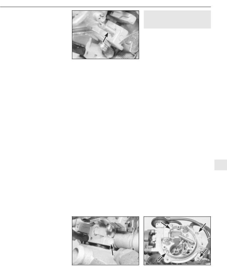
17Move the throttle lever to the fully open position, and measure the choke valve gap between the lower side of the choke plate and the wall of the primary barrel. Check that the gap is as given in the Specifications.
18If necessary, adjust the choke valve gap by bending the “adjuster segment (2)” If the gap is too small, enlarge gap “B”, by levering
with a screwdriver. If the gap is too large, decrease gap “B” using a pair of pliers (see illustration).
19If no further adjustments are to be carried out, refit the bi-metal housing, as described in paragraphs 10 to 14, of this Section.

4A• 10 Fuel and exhaust systems - carburettor models
19.18 Choke valve gap adjustment
1Choke operating lever
2Adjuster segment
B Choke valve gap
Fast idle cam position
20With the bi-metal housing removed, and the choke valve gap “ B” , correctly set, continue as follows.
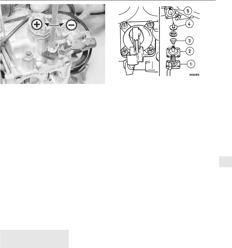
21Open the throttle valve, then close the
choke valve using light finger pressure on the choke drive lever (see illustration). Close the
throttle valve.
22Check that the fast idle speed adjustment screw is resting against the stop on the second highest step of the fast idle cam.
23If adjustment is required, first check that the choke return spring is correctly positioned, then adjust by bending the adjustment lever.
24Refit the bi-metal housing, as described in paragraphs 10 to 14 of this Section.
19.21 Fast idle cam adjustment
1Fast idle cam
2Adjustment lever
3Choke drive lever
4Fast idle speed adjustment screw
adjustment, an an exhaust gas
required
25 Check the idle speed and mixture, as described in Section 14. The idle speed must be correct before attempting to check or adjust the fast idle speed.
26 With the engine at normal operating temperature, and a tachometer connected according to the equipment manufacturer’s instructions, continue as follows.
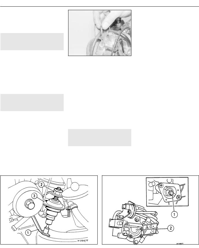
27Position the fast idle speed adjustment
screw on the second highest step of the fast idle cam (see illustration).
28Start the engine without touching the throttle pedal, and check that the fast idle speed is as specified. If adjustment is required, stop the engine and continue as follows.
29Remove the tamperproof cap from the fast idle speed adjustment screw, ensure that
no local or national laws are being broken by doing so (see illustration).
30Ensure that the adjustment screw is still resting on the second highest step of the fast idle cam, then start the engine, again without touching the throttle pedal.
31Turn the adjustment screw using a screwdriver, until the specified fast idle speed is obtained.
32If the cooling fan cuts in during the adjustment procedure, stop the adjustments, and continue when the cooling fan stops.
33On completion of adjustment, stop the engine and disconnect the tachometer.
34Fit a new tamperproof cap to the fast idle speed adjustment screw, where this is required by law.
20 Automatic choke vacuum |
3 |
pull-down units - removal, |
|
refitting and adjustment |
Main diaphragm unit
Note: Refer to Section 2 before proceeding. A new star clip must be used when refitting the diaphragm unit. Test vacuum units as described in Section 16, paragraph 1.
Removal
1 Proceed as described in Section 17, paragraphs 1 and 2.
2 Disconnect the diaphragm unit vacuum pipes.
3 Using a pin punch, tap out the roll pin securing the diaphragm unit to the carburettor top cover.
4 Note the position of the bi-metal housing alignment marks as an aid to refitting, if necessary making additional marks for clarity, then remove the three securing screws, and lift off the bi-metal housing. Place the housing to one side, taking care not to strain the coolant hoses or electric choke heater wiring.
|
|
|
|
|
|
19.27 Fast idle speed adjustment |
|
||
3 |
19.29 Tamperproof cap (arrowed) fast idle speed adjustment |
|||
Fast idle speed adjustment screw |
||||
4 |
Screw positioned on second highest step of cam |
screw |
||
Fuel and exhaust systems - carburettor models 4A• 11
20.12A Choke vacuum pull-down adjustment |
20.12B Checking the vacuum pull-down gap using a twist drill |
1 Adjustment screw 2 Diaphragm unit A Twist drill |
|
5 Remove the three screws securing the choke assembly to the carburettor body. Allow the choke assembly to drop down, but do not disconnect the choke linkage.
6 Remove the star clip that secures the diaphragm unit to the carburettor top cover, and withdraw the diaphragm unit.
Refitting
7 Refitting is a reversal of removal, but use a new star clip to secure the diaphragm unit to the carburettor top cover. Before refitting the air box to the top of the carburettor, check and if necessary adjust the choke pull-down, as follows.
Vacuum pull-down
Adjustment
8With the air cleaner or air box removed from the top of the carburettor, as described in Section 17, paragraph 2, continue as follows.
9Note the position of the bi-metal housing alignment marks as an aid to refitting, if necessary making additional marks for clarity, then remove the three securing screws, and lift off the bi-metal housing. Place the housing to one side, taking care not to strain the coolant hoses or electric choke heater wiring.
10Position the fast idle speed adjustment screw on the highest step of the fast idle cam, and check that the choke valve is closed.
11Move the pull-down arm towards the diaphragm unit by pushing on the adjustment screw until resistance is felt. Hold the arm in this position.
12Using a drill shank of appropriate diameter, or a similar item, measure the clearance between the lower side of the choke plate and the wall of the primary barrel
(see illustrations). Check that the clearance is as given for the “ small” choke pull-down gap in the Specifications.
13 If adjustment is necessary, turn the adjustment screw in the appropriate direction, using an Allen key, until the clearance is correct.
14Now push the pull-down arm towards the diaphragm unit as far as its stop, and hold the arm in this position.
15As before measure the clearance between the lower side of the choke plate and the wall of the primary barrel. Check that the clearance is as given for the “ large” choke pull-down gap in the Specifications.
16If adjustment is necessary, turn the adjustment screw in the appropriate direction until the clearance is correct.
17Connect the bi-metal spring to the choke lever, position the bi-metal housing on the choke housing and loosely fit the securing screws. Align the marks on the bi-metal housing and the choke housing as noted during removal, then tighten the securing screws.
18Refit the air box to the top of the carburettor on completion.
Secondary pull-down solenoid
Removal
19This unit operates in conjunction with the main diaphragm unit.
20To remove the solenoid unit, first continue as described in Section 17, paragraphs 1 and
21Disconnect the diaphragm unit vacuum pipe.
solenoid securing screw and earth lead
22 Disconnect the wiring plug, then unscrew the securing screw, and withdraw the solenoid unit and its mounting bracket from the carburettor. Note that the securing screw
also secures the wiring plug earth lead (see illustration).
Refitting
23 Refitting is a reversal of removal, but ensure that the wiring plug earth lead is in place under the solenoid bracket securing screw.
21 Carburettor filter - removal |
3 |
and refitting |
|
|
|
4A
Removal
1A small tubular filter gauze is fitted into the carburettor top cover’s fuel inlet union to remove any particles of dirt from the fuel.
2To ensure a clean fuel supply and to prevent the risk of misfiring, poor starting or other problems due to a restricted fuel supply, this filter must be cleaned and/or renewed at the interval specified in Chapter 1.
3To reach the filter, remove the air cleaner or air box, as applicable, then disconnect and plug the hose from the fuel pump or vapour separator to the top cover union.
4Remove the filter by hooking it out with a small screwdriver, or by snaring it with a long thin screw (3 mm thread size, screwed approximately 5 mm into the filter).
5If the filter is blocked or heavily fouled, or if it is torn, distorted or damaged in any way, it must be renewed. If it is fit for further use, clean it using a jet of compressed air or by brushing away particles of dirt with an old soft toothbrush. Then flushing it in clean solvent, taking care not to allow any overspray to get into your eyes; if petrol is used, take care to prevent the risk of fire.
4A• 12 Fuel and exhaust systems - carburettor models
Refitting
6 On refitting the filter, press it into the union until it catches (see illustration). The
remainder of the reassembly procedure is the reverse of removal.
22 Throttle valve dashpot |
2 |
(automatic models) - |
|
adjustment |
1Remove the air cleaner or air box, refer to Section 3.
2Ensure that the lever (see illustration) is in
the idling position.
3 Slacken the locknut and unscrew the dashpot until a gap of 0.05 mm (0.002 in) exists between the lever and the dashpot tip. Then screw the dashpot downwards 2.5 full turns and tighten the locknut.
4 Refit all removed components.
23 Throttle position sensor |
2 |
(automatic transmission |
|
models) - removal and refitting |
Removal
1Disconnect the battery earth lead.
2Disconnect the wiring plug from the sensor.
3Either unscrew the two securing screws and withdraw the sensor from its bracket, or unbolt the bracket.
Refitting
4 Refitting is the reverse of the removal procedure, noting the following points.
a)Install the sensor when the throttle valve is fully closed and ensure that the adapter, “1” (see illustration), seats correctly on the throttle valve spindle.
b)Tighten the screws carefully.
24 Idle speed increase valve - |
2 |
testing |
|
|
|
1Certain models are fitted with an idle speed increase valve that is attached to the side of the carburettor.
2To test the operation of this valve first remove the air filter and vacuum hose.
3With the valve’s plug connected, have someone turn the ignition on (but do not start the engine). A mechanical shifting noise should be heard. If not replace the unit.
4After refitting replace the vacuum hose and air filter.
25 Idle cut-off solenoid (1.8 litre 2 models) - description and
testing
Note: Refer to Section 2 before proceeding
Description
1 On 1.8 litre models, the carburettor is fitted with an idle cut-off solenoid. This is an electrically operated valve, which interrupts the idle mixture circuit when the ignition is
switched off, thus preventing the engine from running-on (see illustration).
2 The idle cut-off solenoid is energised all the time that the ignition is switched on. A defective solenoid, or a break in its power supply, will cause the engine to stall or idle roughly, although it will run normally at speed.
Testing
3If the operation of the solenoid is suspect, first check that battery voltage is present at the solenoid terminal when the ignition is switched on. Use a 12 volt test lamp or similar test device.
4If no voltage is present, then the fault lies in the wiring to the solenoid. If voltage is present, the solenoid can be tested as follows.
5With the solenoid unscrewed from the carburettor, connect the body of the solenoid to the negative terminal of a 12 volt battery. When the battery positive terminal is connected to the solenoid centre terminal, there should be an audible click, and the needle at the tip of the solenoid should retract.
6A defective idle cut-off solenoid must be renewed.
26 Inlet manifold - removal and |
3 |
refitting |
|
|
|
Note: Refer to Section 2 before proceeding. A new manifold gasket must be used on refitting
Removal
1Disconnect the battery negative lead.
2Drain the cooling system, as described in Chapter 3.
3Proceed as described in Section 13, paragraphs 2 to 7 inclusive, ignoring the reference to coolant spillage in paragraph 5.
automatic transmission |
transmission |
1 Lever |
2 Locknut |
3 Dashpot |
1 Adapter |
2 Sensor |
|
|
Fuel and exhaust systems - carburettor models 4A• 13
(arrowed) - 1.8 litre models
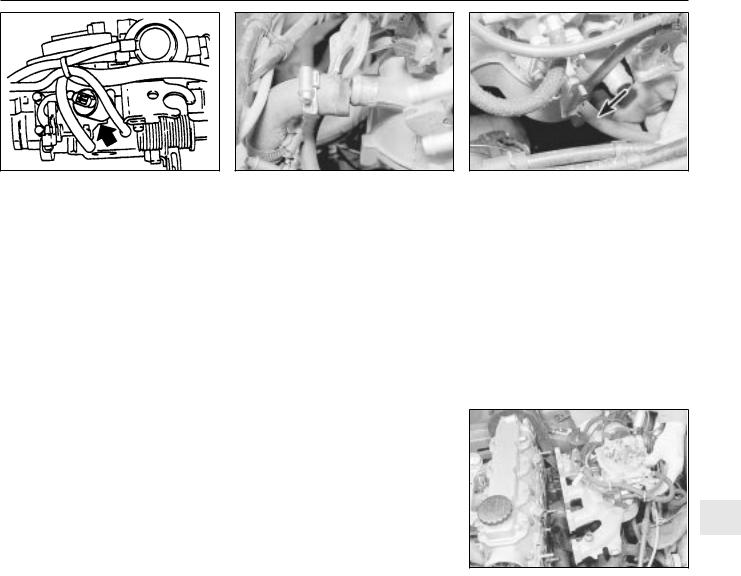
4Disconnect the coolant hose from the rear of the manifold (see illustration).
5Where applicable, disconnect the camshaft
cover breather hose from the rear of the manifold (see illustration).
6Unscrew the union and disconnect the brake servo vacuum hose from the manifold.
7On 1.4 and 1.6 litre models, disconnect the wiring from the temperature gauge sender.
8Unscrew and remove the top alternator mounting nut and bolt.
9On 1.4 and 1.6 litre models, disconnect and remove the stub hose that connects the crankcase breather tube to the rear of the camshaft housing.
10Make a final check to ensure that all relevant hoses, pipes and wires have been disconnected.
11Unscrew the securing nuts, and withdraw
the manifold from the cylinder head (see illustration). Note the position of the rear
engine lifting bracket, which is secured by one of the manifold nuts, and recover the manifold
26.4 Disconnecting the coolant hose . . .
gasket.
12It is possible that some of the manifold studs may be unscrewed from the cylinder head when the manifold securing nuts are unscrewed. In this event, the studs should be screwed back into the cylinder head once the manifold has been removed, using two manifold nuts locked together.
13If desired, the carburettor can be removed from the manifold, referring to Section 13, if necessary.
Refitting
14 Refitting is a reversal of removal, remembering the following points.
15If the carburettor has been removed from the manifold, refit it, using a new gasket.
16If the alternator mounting bracket has been unbolted from the manifold, refit it before refitting the manifold, as access to the securing bolt is extremely limited once the manifold is in place.
17Refit the manifold using a new gasket,
26.5 . . .and the camshaft cover breather hose (arrowed) from the inlet manifold - 1.6 litre model
and ensure that the engine lifting bracket is in place under the relevant manifold nut. Tighten the nuts to the specified torque.
18Ensure that all relevant hoses, pipes and wires are correctly reconnected.
19Refill the cooling system, as described in Chapter 3.
20Check the throttle cable free play and adjust if necessary, as described in Section
21If the carburettor has been disturbed, check and if necessary adjust the idle speed and mixture, as described in Section 14.
4A
26.11Withdrawing the inlet manifold -
1.6litre model
4A• 14 |
Notes |
|
|

12• 1
Chapter 12
Body electrical systems
Contents
Aerial - removal and refitting . . . . . . . . . . . . . . . . . . . . . . . . . . . . . . .47 Aerial mast, electric - removal and refitting . . . . . . . . . . . . . . . . . . . .48 Airbag - general . . . . . . . . . . . . . . . . . . . . . . . . . . . . . . . . . . . . . . . . .55 Airbag contact unit - removal and refitting . . . . . . . . . . . . . . . . . . . . .58 Airbag control unit - removal and refitting . . . . . . . . . . . . . . . . . . . . .61 Airbag unit, drivers side - removal and refitting . . . . . . . . . . . . . . . . .56 Airbag unit, passengers side - removal and refitting . . . . . . . . . . . . .59 Anti-theft alarm - general . . . . . . . . . . . . . . . . . . . . . . . . . . . . . . . . . .53 Anti-theft alarm system components - removal and refitting . . . . . . .54 Bracket, passenger airbag unit - removal and refitting . . . . . . . . . . .60 Brake lamp switch - removal and refitting . . . . . . . . . . . . . . . . . . . . .12 Central door locking components - removal and refitting . . . . . . . . .46 Check control system components - removal and refitting . . . . . . . .21 Cigarette lighter - removal and refitting . . . . . . . . . . . . . . . . . . . . . . .15 Clock - removal and refitting . . . . . . . . . . . . . . . . . . . . . . . . . . . . . . .16 Courtesy lamp switch - removal and refitting . . . . . . . . . . . . . . . . . . .10 Direction indicator/lighting switch - removal and refitting . . . . . . . . . .5 Electric door mirror switch - removal and refitting . . . . . . . . . . . . . . . .8 Electric window components - removal and refitting . . . . . . . . . . . . .44 Electric window controls - programming . . . . . . . . . . . . . . . . . . . . . .45 Electrical fault-finding - general information . . . . . . . . . . . . . . . . . . . . .2 Exterior lamp bulbs - renewal . . . . . . . . . . . . . . . . . . . . . . . . . . . . . . .34 Facia panel switches - removal and refitting . . . . . . . . . . . . . . . . . . . .7 Front indicator lamp unit - removal and refitting . . . . . . . . . . . . . . . .29 Front foglamp - removal, refitting and adjustment . . . . . . . . . . . . . . .31 Fuses and relays - general . . . . . . . . . . . . . . . . . . . . . . . . . . . . . . . . . .3 General information and precautions . . . . . . . . . . . . . . . . . . . . . . . . . .1 Handbrake “on” warning lamp switch - removal and refitting . . . . . .13 Headlamp aim adjustment motor - removal and refitting . . . . . . . . . .26 Headlamp dim-dip system - general, removal and refitting . . . . . . . .28 Headlamp unit - removal and refitting . . . . . . . . . . . . . . . . . . . . . . . .25 Headlamp washer fluid non-return valve - removal and refitting . . . .43
Headlamp wiper motor - removal and refitting . . . . . . . |
. . . . . . . . . . |
.40 |
Headlamps - alignment . . . . . . . . . . . . . . . . . . . . . . . . |
. . . . . . . . . . . |
27 |
Heated front seats - general . . . . . . . . . . . . . . . . . . . . . |
. . . . . . . . . . . |
17 |
Horn(s) - removal and refitting . . . . . . . . . . . . . . . . . . . |
. . . . . . . . . . . |
22 |
Ignition switch and lock cylinder - removal and refitting |
. . . . . . . . . . |
.4 |
Instrument panel - removal and refitting . . . . . . . . . . . |
. . . . . . . . . . . |
18 |
Instrument panel components - removal and refitting . |
. . . . . . . . . . . |
19 |
Interior lamp bulbs - renewal . . . . . . . . . . . . . . . . . . . . |
. . . . . . . . . . . |
24 |
Interior lamps - removal and refitting . . . . . . . . . . . . . . |
. . . . . . . . . . . |
23 |
Luggage compartment lamp switch - removal and refitting . . . . . . . |
11 |
|
Number plate lamp - removal and refitting . . . . . . . . . . |
. . . . . . . . . . . |
33 |
Oil pressure warning lamp switch - removal and refitting . . . . . . . . . |
14 |
|
Radio/cassette player - removal and refitting . . . . . . . . |
. . . . . . . . . . . |
50 |
Rear lamp unit - removal and refitting . . . . . . . . . . . . . |
. . . . . . . . . . . |
32 |
Reversing lamp switch . . . . . . . . . . . . . . . . . . . . . . . . . |
See Chapter 7A |
|
Side repeater lamp - removal and refitting . . . . . . . . . . |
. . . . . . . . . . . |
30 |
Speakers - removal and refitting . . . . . . . . . . . . . . . . . |
. . . . . . . . . . . |
49 |
Speedometer cable - removal and refitting . . . . . . . . . |
. . . . . . . . . . . |
52 |
Steering wheel (with airbag) - removal and refitting . . . |
. . . . . . . . . . . |
57 |
Sunroof motor - removal and refitting . . . . . . . . . . . . . |
. . . . . . . . . . . |
51 |
Sunroof operating switch - removal and refitting . . . . . |
. . . . . . . . . . . |
.9 |
Tailgate wiper motor - removal and refitting . . . . . . . . . |
. . . . . . . . . . . |
39 |
Trip computer components - removal and refitting . . . |
. . . . . . . . . . . |
20 |
Wash/wipe switch - removal and refitting . . . . . . . . . . |
. . . . . . . . . . . |
.6 |
Washer fluid reservoir - removal and refitting . . . . . . . . |
. . . . . . . . . . . |
41 |
Washer nozzles - removal and refitting . . . . . . . . . . . . |
. . . . . . . . . . . |
37 |
Washer pump - removal and refitting . . . . . . . . . . . . . . |
. . . . . . . . . . . |
42 |
Windscreen wiper motor and linkage - removal and refitting . . . . . . . |
38 |
|
Wiper arms - removal and refitting . . . . . . . . . . . . . . . . |
. . . . . . . . . . . |
36 |
Wiper blades - renewal . . . . . . . . . . . . . . . . . . . . . . . . . |
. . . . . . . . . . . |
35 |
Wiring diagrams - general . . . . . . . . . . . . . . . . . . . . . . |
. . . . . . . . . . . |
62 |
Degrees of difficulty
Easy, suitable for |
1 |
|
|
|
|
|
|
|
|
|
|
||
novice with little |
|
|
|
|
|
|
experience |
|
|
|
|
|
|
|
|
|
|
|
|
|
Specifications |
|
|
|
|
||
Wiper blades |
|
|
|
|
|
|
Type . . . . . . . . . . . . . . . |
. . . . |
. . . . . . . . . . . . . . . . . . . . . . . |
. . . . . . . . . . 19 ins. Champion X-4803 |
|
||
Fuses |
|
|
|
|
|
|
Rating: |
|
|
|
|
|
|
Red . . . . . . . . . . . . . . |
. . . . |
. . . . . . . . . . . . . . . . . . . . . . . |
. . . . . . . . . . 10 A |
|
|
|
Blue . . . . . . . . . . . . . . |
. . . . |
. . . . . . . . . . . . . . . . . . . . . . . |
. . . . . . . . . . 15 A |
|
|
|
Yellow . . . . . . . . . . . . |
. . . . |
. . . . . . . . . . . . . . . . . . . . . . . |
. . . . . . . . . . 20 A |
|
|
|
Green . . . . . . . . . . . . |
. . . . |
. . . . . . . . . . . . . . . . . . . . . . . |
. . . . . . . . . . 30 A |
|
|
|
Torque wrench settings |
Nm |
lbf ft |
12 |
|||
Airbag unit to steering wheel . . . . . . . . . . . . . . . . . . . . . . . |
10. . . . . . . . . . |
7 |
|
|||
Airbag control . . . . . . . . |
. . . . |
. . . . . . . . . . . . . . . . . . . . . . . |
10. . . . . . . . . . |
7 |
|
|
Brackets, passenger airbag . . . . . . . . . . . . . . . . . . . . . . . . |
22. . . . . . . . . . |
16 |
|
|
||
Passenger airbag to bracket . . . . . . . . . . . . . . . . . . . . . . . |
8. . . . . . . . . . |
6 |
|
|
||
Steering to column . . . . |
. . . . |
. . . . . . . . . . . . . . . . . . . . . . . |
25. . . . . . . . . . |
18 |
|
|

12• 2 Body electrical systems
Warning: Before carrying out work on the electrical
system, read through the precautions given in “Safety
the beginning of this manual, and 5.
Caution: If the radio/cassette player fitted to the vehicle is one with an anti-theft security code, as the standard unit is, refer to “Radio/cassette player anti-theft system - precaution” in the Reference Section of this manual before disconnecting the battery.
2Electrical fault-finding - general information
Note: Refer to the precautions given in “Safety first!” (at the beginning of this manual) and to Section 1 of this Chapter before starting work. The following tests relate to testing of the main electrical circuits, and should not be used to test delicate electronic circuits (such as antilock braking systems), particularly where an electronic control module is used.
A typical electrical circuit consists of an electrical component, any switches, relays, motors, fuses, fusible links or circuit breakers related to that component, and the wiring and connectors that link the component to both
the battery and the chassis. To help to pinpoint a problem in an electrical circuit, wiring diagrams are included at the end of this Chapter.
Before attempting to diagnose an electrical fault, first study the appropriate wiring diagram, to obtain a complete understanding of the components included in the particular circuit concerned. The possible sources of a fault can be narrowed down by noting whether other components related to the circuit are operating properly. If several components or circuits fail at one time, the problem is likely to be related to a shared fuse or earth connection.
Electrical problems usually stem from simple causes, such as loose or corroded connections, a faulty earth connection, a blown fuse, a melted fusible link, or a faulty relay (refer to Section 3 for details of testing relays). Visually inspect the condition of all fuses, wires and connections in a problem circuit before testing the components. Use the wiring diagrams to determine which terminal connections will need to be checked, to pinpoint the trouble-spot.
The basic tools required for electrical faultfinding include the following:
a)a circuit tester or voltmeter (a 12-volt bulb with a set of test leads can also be used for certain tests).
b)a self-powered test light (sometimes known as a continuity tester).
c)an ohmmeter (to measure resistance).
d)a battery.
e)a set of test leads.
f)a jumper wire, preferably with a circuit breaker or fuse incorporated, which can
be used to bypass suspect wires or electrical components.
Before attempting to locate a problem with test instruments, use the wiring diagram to determine where to make the connections.
To find the source of an intermittent wiring fault (usually due to a poor or dirty connection, or damaged wiring insulation), a “wiggle” test can be performed on the wiring. This involves wiggling the wiring by hand, to see if the fault occurs as the wiring is moved. It should be possible to narrow down the source of the fault to a particular section of wiring. This method of testing can be used in conjunction with any of the tests described in the following sub-Sections.
Apart from problems due to poor connections, two basic types of fault can occur in an electrical circuit - open-circuit, or short-circuit.
Open-circuit faults are caused by a break somewhere in the circuit, which prevents current from flowing. An open-circuit fault will prevent a component from working, but will not cause the relevant circuit fuse to blow.
Short-circuit faults are caused by a “short” somewhere in the circuit, which allows the current flowing in the circuit to “escape” along an alternative route, usually to earth. Shortcircuit faults are normally caused by a
breakdown in wiring insulation, which allows a feed wire to touch either another wire, or an earthed component such as the bodyshell. A short-circuit fault will normally cause the relevant circuit fuse to blow.
Finding an open-circuit
To check for an open-circuit, connect one lead of a circuit tester or voltmeter to either the negative battery terminal or a known good earth.
Connect the other lead to a connector in the circuit being tested, preferably nearest to the battery or fuse.
Switch on the circuit, remembering that some circuits are live only when the ignition switch is moved to a particular position.
If voltage is present (indicated either by the tester bulb lighting or a voltmeter reading, as applicable), this means that the section of the circuit between the relevant connector and the battery is problem-free.
Continue to check the remainder of the circuit in the same fashion.
When a point is reached at which no voltage is present, the problem must lie between that point and the previous test point with voltage. Most problems can be traced to a broken, corroded or loose connection.
Finding a short-circuit
To check for a short-circuit, first disconnect the load(s) from the circuit (loads are the components that draw current from a circuit, such as bulbs, motors, heating elements, etc.).
Remove the relevant fuse from the circuit, and connect a circuit tester or voltmeter to the fuse connections.
Switch on the circuit, remembering that some circuits are live only when the ignition switch is moved to a particular position.
If voltage is present (indicated either by the tester bulb lighting or a voltmeter reading, as applicable), this means that there is a shortcircuit.
If no voltage is present, but the fuse still blows with the load(s) connected, this indicates an internal fault in the load(s).
Finding an earth fault
The battery negative terminal is connected to “ earth” (the metal of the engine/transmission and the car body), and most systems are wired so that they only receive a positive feed. The current returning through the metal of the car body. This means that the component mounting and the body form part of that circuit. Loose or corroded mountings can therefore cause a range of electrical faults, ranging from total failure of a circuit, to a puzzling partial fault. In particular, lights may shine dimly (especially when another circuit sharing the same earth point is in operation). Motors (e.g. wiper motors or the radiator cooling fan motor) may run slowly, and the operation of one circuit may have an affect on another. Note that on many vehicles, earth straps are used between certain components, such as the engine/transmission and the body, usually where there is no metal-
Body electrical systems 12• 3
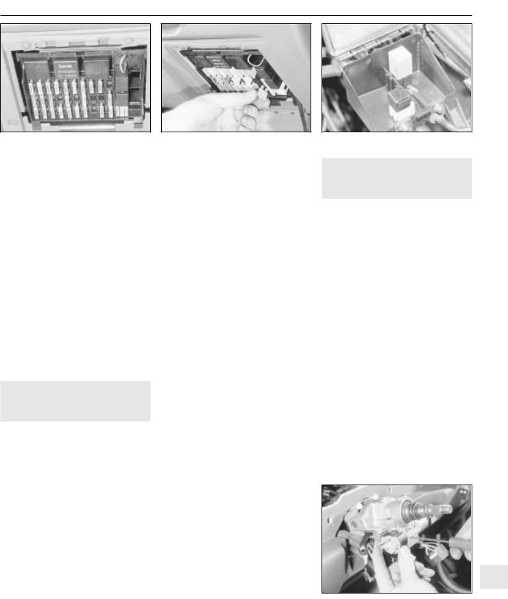
3.2Main fuses and relays in facia panel -
2.0litre SRi model shown
to-metal contact between components, due to flexible rubber mountings, etc.
To check whether a component is properly earthed, disconnect the battery, and connect one lead of an ohmmeter to a known good earth point. Connect the other lead to the wire or earth connection being tested. The resistance reading should be zero; if not, check the connection as follows.
If an earth connection is thought to be faulty, dismantle the connection, and clean back to bare metal both the bodyshell and the wire terminal or the component earth connection mating surface. Be careful to remove all traces of dirt and corrosion, then use a knife to trim away any paint, so that a clean metal-to-metal joint is made. On reassembly, tighten the joint fasteners securely; if a wire terminal is being refitted, use serrated washers between the terminal and the bodyshell, to ensure a clean and secure connection. When the connection is remade, prevent the onset of corrosion in the future by applying a coat of petroleum jelly or silicone-based grease.
3 Fuses and relays - general
Fuses
1Fuses are designed to break a circuit when a predetermined current is reached, to protect the components and wiring which could be damaged by excessive current flow. Any excessive current flow will be due to a fault in the circuit, usually a short-circuit (Section 2).
2The main fuses and relays are located in a
panel at the lower right-hand side of the facia, under a hinged cover (see illustration).
3The circuits protected by the various fuses and relays are marked on the inside of the panel cover.
4A blown fuse can be recognised from its melted or broken wire.
5To remove a fuse, first ensure that the relevant circuit is switched off. Then open the
cover and pull the relevant fuse or relay from the panel (see illustration). If desired, the lower
end of the panel can be tilted forwards, after releasing the retaining clips to improve access.
2.0 litre model shown
6Before renewing a blown fuse, trace and rectify the cause, and always use a fuse of the correct rating. Never substitute a fuse of a higher rating, or make temporary repairs using wire or metal foil, as more serious damage or even fire could result.
7Spare fuses are provided in the blank terminal positions in the fusebox.
8Note that the fuses are colour-coded, see Specifications. Refer to the wiring diagrams for details of the fuse ratings and the circuits protected.
Relays
9A relay is an electrically operated switch, which is used for the following reasons:
a)A relay can switch a heavy current remotely from the circuit in which the current is flowing, allowing the use of lighter-gauge wiring and switch contacts.
b)A relay can receive more than one control input, unlike a mechanical switch.
c)A relay can have a timer function - for example, the intermittent wiper relay.
10Most of the relays are located at the rear of the main fusebox (remove the securing screws and pull the fusebox forwards to improve access). The rear wiper motor relay is located in the tailgate, behind the tailgate trim panel. On some models, additional enginerelated relays are located in the relay box mounted on the left-hand side of the engine compartment.
11On certain models, additional relays are
located in a box at the left-hand rear of the engine compartment (see illustration).
12If a circuit or system controlled by a relay develops a fault, and the relay is suspect, operate the system. If the relay is functioning, it should be possible to hear it “click” as it is energised. If this is the case, the fault lies with the components or wiring of the system. If the relay is not being energised, then either the relay is not receiving a main supply or a switching voltage, or the relay itself is faulty. Testing is by the substitution of a known good unit, but be careful - while some relays are identical in appearance and in operation, others look similar but perform different functions.
13To remove a relay, first ensure that the relevant circuit is switched off. The relay can then simply be pulled out from the socket, and pushed back into position.
2.0 litre SRi model shown |
|
4 Ignition switch and lock |
3 |
cylinder - removal and |
|
refitting |
Removal
1Disconnect the battery negative lead.
2Turn the steering wheel as necessary to expose the two front steering column shroud securing screws, which are covered by plastic caps. Prise out the caps and remove the screws.
3Remove the three securing screws from the underside of the lower column shroud, then remove both the upper and lower shrouds.
4To remove the lock cylinder, insert the ignition key and turn it to position “II”.
5Insert a thin rod into the hole in the lock housing, then press the rod to release the detent spring, and pull out the lock cylinder using the key.
6The ignition switch is secured to the steering lock housing by two grub screws.
Disconnect the wiring plug, and remove the screws to extract the switch (see illustration).
Removal of the steering wheel, may aid removal. Refer to Chapter 10 or Section 57, as applicable. It is recommended that the switch and the lock cylinder are not both removed at the same time, so that their mutual alignment is not lost.
Refitting
7 Refitting is a reversal of removal.
12
screw
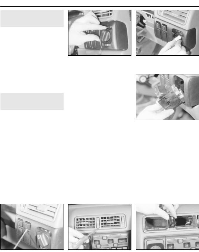
12• 4 Body electrical systems
5 Direction indicator/lighting |
2 |
switch - removal and refitting |
Removal
1Disconnect the battery negative lead.
2Turn the steering wheel as necessary to expose the two front steering column shroud securing screws, which are covered by plastic caps. Prise out the caps and remove the screws.
3Remove the three securing screws from underside of the lower column shroud, remove both the upper and lower shrouds.
4Disconnect the wiring plug from the switch.
5Depress the switch retaining clip, and withdraw the switch from the housing.
Refitting
6 Refitting is a reversal of removal.
6Wash/wipe switch - removal 2 and refitting
Proceed as described in Section 5.
7 Facia panel switches - |
2 |
removal and refitting |
|
|
|
1 Disconnect the battery negative lead. |
|
Lighting switch |
|
Removal
2Turn the switch to the “ dipped beam on” position, then insert a small screwdriver or rod through the hole in the bottom of the switch
knob to depress the knob retaining clip. Pull the knob from the switch (see illustration).
3Press the two now-exposed switch securing clips towards the switch spindle,
then pull the switch from the facia and disconnect the wiring plug (see illustrations).
4Note that the switch assembly cannot be dismantled, and if any part of the switch is faulty, the complete assembly must be renewed.
lightning switch knob retaining clip
Refitting
5 Refitting is a reversal of removal.
Push-button switches
Removal
6 First check beneath the switch, if there is a small hole in the facia, insert a slim screwdriver or metal rod into it. Release the switch retaining spring clip by pressing it upwards against the switch, then remove the switch and disconnect its wiring. If there is no hole, remove the switch by prising it out of the facia using a small screwdriver. Lever gently under the switch’s lower edge (use adhesive tape or a piece of card to protect the facia’s
finish). Disconnect the switch wiring plug and withdraw the switch (see illustration).
Refitting
7 Refitting is a reversal of removal.
Headlamp aim adjustment switch
8 The procedure is as described for pushbutton switches.
Hazard warning switch
Removal
9Using a screwdriver, carefully prise the cap from the switch (see illustration).
10Using a screwdriver with a piece of card under the blade to avoid damage to the facia trim, prise the ventilation nozzle from the facia.
11Prise the switch from the facia and disconnect the wiring (see illustration).
7.3A Press the switch securing clips towards the switch spindle . . .
7
Refitting
12 Refitting is a reversal of removal.
Heater blower motor switch
Removal
13 Remove the heater control panel, as described in Chapter 11.
14 Disconnect the wiring plug from the switch, if not already done.
15 Prise the switch out from the rear of the heater control panel.
Refitting
16 Refitting is a reversal of removal, but refer to Chapter 11, when refitting the heater control panel.
facia |
warning flasher switch |
flasher switch from the facia |
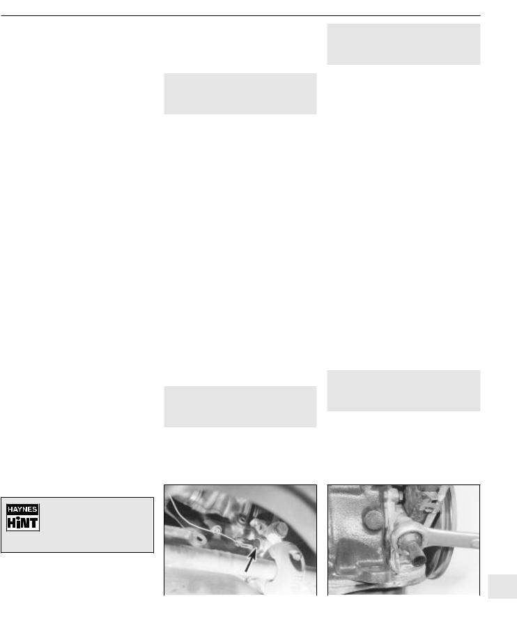
Body electrical systems 12• 5
|
|
4 |
Disconnect the wiring and remove the |
|
8 Electric door mirror switch - |
2 |
|||
switch. |
||||
removal and refitting |
Refitting |
|||
|
|
5 |
Refitting is a reversal of removal. |
|
Removal
1Disconnect the battery negative lead.
2Prise the plastic surround from the door interior handle.
3Free the trim panel from the top edge of the door by releasing the securing clips. This can be done using a screwdriver, but it is preferable to use a forked tool, to minimise the possibility of damage to the trim panel and the clips.
4Note the position of the mirror switch wiring connector in the bracket at the top of the door, then separate the two halves of the connector.
5Prise the switch from the door trim panel, and feed the wiring through the panel.
Refitting
6 Refitting is a reversal of removal, but ensure that the wiring is correctly routed, so as not to foul the door interior handle mechanism.
9 Sunroof operating switch - |
2 |
removal and refitting |
|
|
|
Removal
1Disconnect the battery negative lead.
2Prise the courtesy lamp from the roof trim panel, and disconnect the wiring.
3Remove the two trim panel securing screws, and withdraw the trim panel from the roof, disconnecting the wiring from the sunroof operating switch.
4Release the securing clips, then pull the switch from the rear face of the trim panel.
Refitting
5 Refitting is a reversal of removal.
10 Courtesy lamp switch - |
2 |
removal and refitting |
|
|
|
11 Luggage compartment lamp 2 switch - removal and refitting
Removal
1Disconnect the battery negative lead.
2Open the boot lid or tailgate, as applicable, and remove the switch securing screw.
3Withdraw the switch from the body panel, and pull the wiring out sufficiently to prevent it from springing back into the body.
4Disconnect the wiring and remove the switch.
Refitting
5 Refitting is a reversal of removal.
12 Brake lamp switch - removal |
2 |
and refitting |
|
|
|
Removal
1Disconnect the battery negative lead.
2Remove the lower trim panel from the driver’s footwell.
3Disconnect the wiring plug from the brake
lamp switch, then twist the switch anti-clockwise and remove it from its bracket.
Refitting
4 Refitting is a reversal of removal.
13 Handbrake “on” warning |
3 |
lamp switch - removal and |
|
refitting |
For access to the switch, the handbrake lever must be removed. Removal and refitting of the switch is described as part of the handbrake lever removal and refitting procedure, in Chapter 9.
Tape the wiring to the door pillar, to prevent if falling
back into the door pillar. Alternatively, tie a piece of
string to the wiring to retrieve it.
12
securing screw. |
|
|
|
3 Withdraw the switch from the door pillar, |
(arrowed) viewed from underneath vehicle |
lamp switch - |
|
and pull the wiring out sufficiently to prevent it |
|||
from springing back into the pillar. |
- SOHC model |
SOHC model (engine removed) |
|

12• 6 Body electrical systems
3 To remove the cigarette lighter assembly, simply pull it from the illumination ring assembly. If desired, the illumination ring assembly can be removed, by pulling it from the housing after depressing the retaining clips.
Refitting
4 Refitting is a reversal of removal.
16 Clock - removal and refitting
Removal
1Disconnect the battery negative lead.
2Using a thin-bladed screwdriver, carefully prise the clock from the facia panel.
3Disconnect the wiring plugs and withdraw the clock (see illustration).
Refitting
4 Refitting is a reversal of removal.
17 Heated front seats - general 2
Heating pads are fitted to the front seats of some models. Before attempting to remove a seat so equipped, disconnect the battery and the leads from the heating pad.
securing screw
the clock
18 Instrument panel - removal |
3 |
and refitting |
|
|
|
Removal
1Disconnect the battery negative lead.
2Remove the steering wheel, (Chapter 10).
3Remove the steering column shrouds, and the instrument panel upper and lower trim panels, (Chapter 11).
4Remove the single upper, and two lower, instrument panel securing screws (see illustration).
5Carefully withdraw the instrument panel, and disconnect the speedometer cable and the two wiring plugs. Note that the speedometer cable is retained by a clip, which
must be pressed towards the speedometer to release the cable (see illustration).
wiring plug. Note speedometer cable retaining clip (arrowed)
6 If desired, the instrument panel can be dismantled, with reference to Section 19.
Refitting
7 Refitting is a reversal of removal, but ensure that the speedometer cable is not kinked or twisted between the instrument panel and the bulkhead as the panel is refitted.
19 Instrument panel |
3 |
components - removal and |
|
refitting |
1 With the instrument panel removed, as described in Section 18, continue as follows.
Panel illumination and warning lamp bulbs
Removal
2 Twist the relevant bulbholder clockwise, and withdraw it from the printed circuit board
on the rear of the instrument panel (see illustration).
3 The bulbs are integral with the bulbholders, and must be renewed as a unit.
Refitting
4 Refitting is a reversal of removal.
Voltage stabiliser
Removal
5 Remove the single securing screw from the rear of the instrument panel, then pull the
voltage stabiliser from the contacts on the printed circuit board (see illustration).
Refitting
6 Refitting is a reversal of removal.
Fuel and temperature gauges - “low series” models
Removal
7Pull the trip meter reset pin from the front of the panel.
8Release the two retaining clips at the top of the panel, and remove the panel shroud (see illustration).
9Unscrew the two securing nuts, and withdraw the relevant gauge through the front of the instrument panel.
illumination lamp bulb |
(arrowed) |
shroud |
Body electrical systems 12• 7
20.6 Removing the trip computer display module illumination bulb
(arrowed)
20 Trip computer components - 2 removal and refitting
1 Disconnect the battery lead.
Display module
Removal
2Using a thin-bladed screwdriver, carefully prise the module from the facia panel.
3Disconnect the wiring plug and withdraw the module.
Refitting
4 Refitting is a reversal of removal.
Display module illumination bulb
Removal
5Remove the display module, as described previously in this Section.
6Using a length of rubber sleeving of similar diameter, or an alternator tool, extract the
bulb by inserting the tool through the hole in the side of the display module (see illustration).
Refitting
7 Refitting is a reversal of removal.
Operating switch
Removal
8 Remove the rear section of the centre console, as described in Chapter 11.
9 Release the wiring plug from the switch using a screwdriver.
10 Lift the switch, then pull it down and out from the centre console.
Refitting
11 Refitting is a reversal of removal.
Outside air temperature sensor
Removal
12The sensor is located at the left-hand end of the front bumper (see illustration).
13Prise the cover cap from the bumper, then unclip the sensor, and disconnect the wiring plug.
21 Check control system |
3 |
components - removal and |
|
refitting |
1 Disconnect the battery negative lead.
Warning lamp bulbs
2 The warning lamp bulbs are located in the instrument panel, and removal and refitting are described in Section 19.
Control module
Removal
3The control module is located behind the passenger side of the facia, above the glovebox.
4Remove the glovebox assembly, as described in Chapter 11.
5Disconnect the control module wiring plug, then release the control module from its mounting and withdraw the unit.
Refitting
6 Refitting is a reversal of removal.
Coolant level sensor
Removal
7The coolant level sensor is integral with the coolant expansion tank cap.
8Disconnect the wiring from the top of the cap, then unscrew the cap and withdraw it from the expansion tank.
9If faulty, the complete cap assembly must be renewed.
Refitting
10 Refitting is a reversal of removal.
Washer fluid level sensor
Removal
11The sensor is mounted in the side of the fluid reservoir.
12Disconnect the wiring from the sensor, then unscrew the sensor from the fluid reservoir. If the fluid level is above the level of the sensor, be prepared for fluid spillage.
Refitting
13 Refitting is a reversal of removal.
12
20.12 Trip computer outside air temperature sensor location (arrowed)

12• 8 Body electrical systems
21.18 Engine oil level sensor - DOHC model |
|
22.5 Horn viewed from behind with radiator removed - single |
|
|
horned model |
Brake fluid level sensor
14 The procedure is as described for the coolant level sensor in paragraphs 7 to 10 inclusive.
23 Reach up behind the fuse/relay panel, and pull the sensor from its socket.
Refitting
24 Refitting is a reversal of removal.
23 Interior lamps - removal and |
2 |
refitting |
|
|
|
Engine oil level sensor
Removal
15 Apply the handbrake, jack up the front of
the vehicle, and support securely on axle stands (see “ Jacking and Vehicle Support” )
positioned under the body side members.
16On DOHC models, remove the engine undershield, as described in Chapter 11.
17Disconnect the sensor wiring plug.
18Unscrew the three or four sensor securing screws, as applicable, and withdraw the
sensor, manipulating the float through the hole in the sump (see illustration). Recover the
sealing ring. Be prepared for some oil spillage. 19 Examine the condition of the sealing ring, and renew if necessary.
Refitting
20 Refitting is a reversal of removal. On completion, check, and if necessary top-up, the engine oil level.
Bulb failure sensor
Removal
21The bulb failure sensor is mounted behind the fuse/relay panel in the facia.
22Release the retaining clips from the lower end of the fuse/relay panel, and tilt it forwards.
22 Horn(s) - removal and refitting 2
1 On models with a single horn, the horn is located in front of the radiator. On models with twin horns, the horns are located beneath the washer fluid reservoir, at the left-hand end of the front bumper.
Single horn
Removal
2Disconnect the battery negative lead.
3Remove the radiator grille panel, with reference to Chapter 11.
4Disconnect the wiring from the rear of the horn.
5Reach up behind the mounting bracket, and
unscrew the single nut securing the horn to the bracket (see illustration). Withdraw the horn.
Refitting
6 Refitting is a reversal of removal.
Twin horns
Removal
7Disconnect the battery negative lead.
8Apply the handbrake, then jack up the front
of the vehicle, and support securely on axle stands (see “ Jacking and Vehicle Support” )
positioned under the body side members.
9Remove the securing screws, and withdraw the plastic cover (where fitted) from the bumper/front wing to expose the horns.
10Remove the bolt securing the horn
mounting bracket to the bracket below the washer fluid reservoir (see illustration).
11Withdraw the horns and disconnect the wiring.
12If desired, the horns can be unbolted from the bracket.
Refitting
Removal
1Disconnect the battery negative lead.
2Using a thin-bladed screwdriver, prise the
lamp from its location and disconnect the wiring (see illustration).
Refitting
3 Refitting is a reversal of removal.
24 Interior lamp bulbs - renewal 1
1 Disconnect the battery negative lead.
Courtesy lamp
Note: Some later models are fitted with courtesy lamps for the rear seat passengers, as well as front.
Removal
2Using a thin-bladed screwdriver, prise the lamp from its location and disconnect the wiring.
3On models fitted with a courtesy lamp with integral map reading lamps, the lens must be levered from the housing for access to the bulbs.
bolt (arrowed) - twin horned model |
13 Refitting is a reversal of removal. |
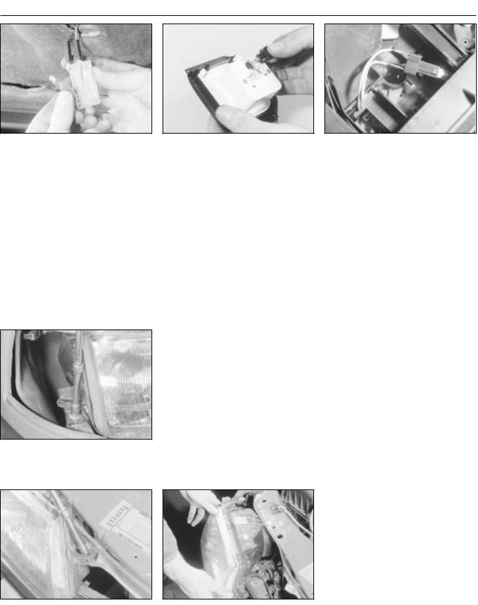
Body electrical systems 12• 9
24.10 Removing the underbonnet lamp bulb
4 Remove the courtesy lamp bulbs by carefully prising it from its location using a thin-bladed screwdriver. Where applicable, the map reading lamp bulbs are a push fit in the bulbholders.
Refitting
5 Refitting is a reversal of removal.
Glovebox lamp
Removal
6Using a thin-bladed screwdriver, prise the lamp from its location and disconnect the wiring.
7Carefully prise the bulb from the lamp.
Refitting
8 Refitting is a reversal of removal.
securing screw
25.5B Unscrewing an upper headlamp securing screw
lamp bulbholder
Luggage compartment, underbonnet and kerb lamps
Removal
9Using a thin-bladed screwdriver, prise the lamp from its location; disconnect the wiring.
10Carefully prise the bulb from the lamp
(see illustration).
Refitting
11 Refitting is a reversal of removal
Cigarette lighter illumination lamp
Removal
12 Slide the ashtray/cigarette lighter assembly from the facia, then disconnect the wiring and pull the bulbholder from the rear of the cigarette lighter housing.
13The bulb is a push fit in the bulbholder.
Refitting
14Refitting is a reversal of removal.
Clock illumination lamp
15Remove the clock, (Section 16).
16Twist the bulbholder and pull it from the rear of the clock (see illustration).
17The bulb is a push fit in the bulbholder.
Trip computer display module illumination lamp
18 Refer to Section 20.
Heater control panel illumination lamp
Removal
19 Remove the heater control panel, as described in Chapter 11.
24.20 Heater control panel illumination lamp bulbholder withdrawn
20Pull the bulbholder from the rear of the control panel (see illustration).
21The bulb is a push fit in the bulbholder.
Refitting
22 Refitting is a reversal of removal.
Facia panel switch illumination lamp
23 If a bulb fails in one of the facia panel switches, the complete switch assembly must be renewed, as described in Section 7, as no individual spare parts are available.
Vanity mirror illumination lamp
Removal
24 Lower the sunvisor and, using a thin-bladed screwdriver, prise out the mirror and diffuser assembly. Pull the bulb(s) from the spring contacts.
Refitting
25 Refitting is a reversal of removal.
|
25 Headlamp unit - removal and |
2 |
|
|
|
|
refitting |
|
|
|
|
|
|
|
|
|
|
Removal |
|
|
|
|
|
1 |
Remove the radiator grille panel, as |
||||
described in Chapter 11. |
|
|
|
|
|
2 |
Remove the front indicator lamp unit, as |
||||
described in Section 29. |
|
|
|
|
|
3 |
Remove the cover from the rear of the |
||||
headlamp unit, and disconnect the wiring |
|||||
plugs from the bulbs. |
|
|
|
|
|
4 |
If applicable, disconnect the wiring plug |
||||
from the headlamp aim adjustment motor. |
|||||
5 |
Remove the three securing screws, and |
||||
withdraw the headlamp unit (see |
|||||
illustrations). Feed the wiring through the |
|||||
headlamp casing as it is removed. |
|
|
|
|
|
6 |
If required, the headlamp lens can be |
||||
removed by releasing the spring clips around |
|||||
its edge. |
|
|
|
|
|
Refitting |
|
|
|
|
|
|
|
|
12 |
||
7 |
Refitting is a reversal of removal. |
|
|
||
8 |
On completion, have the |
headlamp |
|
||
|
|||||
alignment checked, with reference to Section 27.
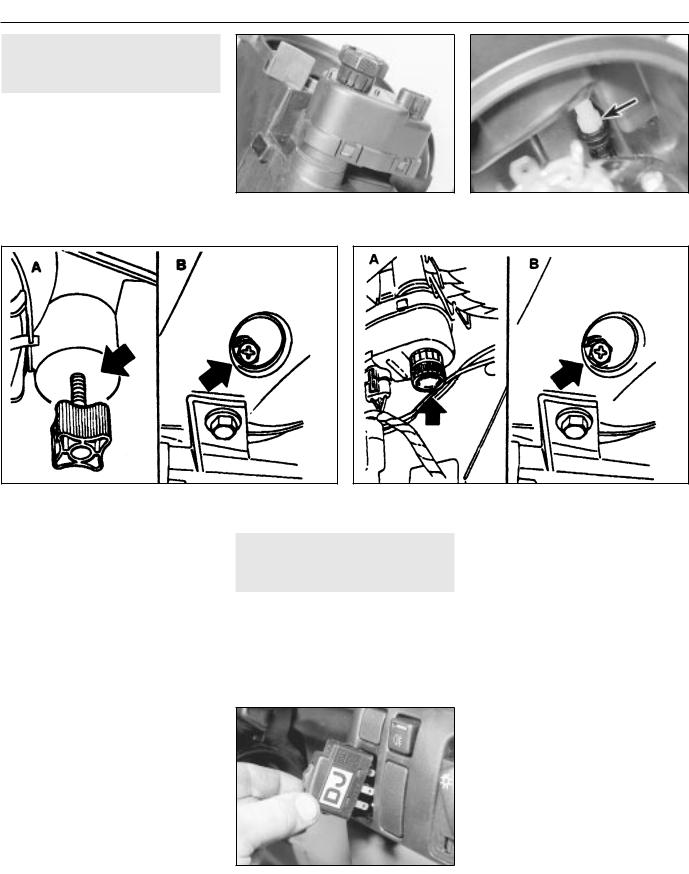
12• 10 Body electrical systems
26 Headlamp aim adjustment |
3 |
motor - removal and refitting |
Removal
1Remove the headlamp, (Section 25).
2Twist the motor clockwise to release it from
the headlamp, then carefully disconnect the motor from the balljoint (see illustrations).
Refitting
3 Refitting is a reversal of removal, but that the motor is correctly engaged with balljoint.
26.2A Headlamp aim adjustment motor |
(arrowed) |
(headlamp removed) |
|
without |
|
|
electric aim adjustment |
A Vertical adjustment screw |
B Horizontal adjustment screw |
|
A Vertical adjustment screw |
B Horizontal adjustment screw |
||
27 Headlamps - alignment |
2 |
|
|
|
|
1Correct alignment of the headlamp beams is most important, not only to ensure good vision for the driver, but also to protect other drivers from being dazzled.
2Accurate alignment should be carried out using optical beam setting equipment.
3In an emergency, adjustments may be
made by turning the adjustment screws shown (see illustrations). If an adjustment is
made, the alignment should be checked using beam setting equipment at the earliest opportunity.
4 All 1992-on models are fitted with the headlamp aim adjustment system, operated
through the facia-mounted switch (see illustration).
a)Position ‘0’, is for correct alignment if just the driving seat is occupied.
b)Position ‘1’, if all seats are occupied.
c)Position ‘2’, if all seats occupied and luggage.
d)Position ‘3’, for just driver and luggage.
28 Headlamp dim-dip system - |
3 |
general, removal and refitting |
General
1The system (where fitted) is governed by the dim-dip control unit mounted either behind and above the glovebox (early models), or behind the main fuse panel (later models).
2The control unit uses the oil pressure warning lamp circuit to ensure that, when the
- 1992-on models
engine is running and the sidelamps are switched on, reduced current is fed to the headlamp dipped-beam circuits. This lights the headlamps with approximately one-sixth of their normal power so that the vehicle cannot be driven using sidelamps alone.
3 To locate the dim-dip control unit, open the main fuse panel covering flap and unclip it from its bottom and top mountings (Section 3). Then use a torch to see whether the unit is fastened to the plastic bracket behind the facia and fuse panel. The unit is usually rectangular, of black plastic, and can be identified by the colours of the five wires leading to it (see applicable wiring diagram).
Removal
4If the unit can be seen, remove the driver’s side lower facia and footwell trim panels (Chapter 11), then unscrew the four retaining screws and lower the plastic bracket until the control unit can be detached.
5If the unit cannot be seen, remove the glovebox assembly (Chapter 11). The unit will be fastened to the underside of the facia top surface.
Refitting
6 Refitting is the reverse of the removal procedure.
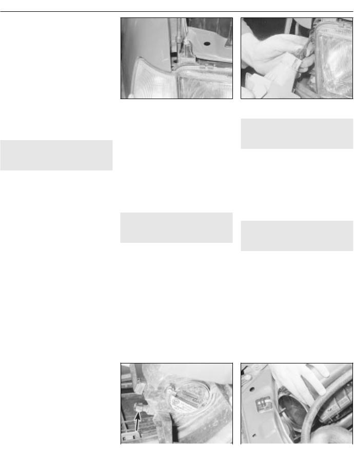
Body electrical systems 12• 11
29 Front indicator lamp unit - |
2 |
removal and refitting |
|
|
|
Removal
1Disconnect the battery negative lead.
2Remove the single indicator lamp unit
securing screw, which is accessible through the hole in the upper body panel (see illustration).
3Pull the lamp unit forwards to release it
from the body, then disconnect the wiring |
unit securing screw |
lamp unit wiring plug |
plug (see illustration). |
Refitting
4 Refitting is a reversal of removal.
30 Side repeater lamp - removal 2 and refitting
Removal
1Disconnect the battery negative lead.
2Remove the wheel arch liner, as described in Chapter 11.
3Working in the engine compartment, disconnect the wiring plug, and detach the earth lead from the body panel.
4Working under the wheel arch, depress the retaining tabs and manipulate the lamp through the outside of the wing, pulling the wiring and the grommet from the inner wing panel.
5The lens can be removed from the lamp by twisting it to release the retaining clips.
6Check the condition of the rubber sealing ring, and renew if necessary.
Refitting
7 Refitting is a reversal of removal.
33 Number plate lamp - removal 2 and refitting
Removal
1Disconnect the battery negative lead.
2Using a thin-bladed screwdriver, carefully prise the lamp surround from the bumper.
3Pull the lamp from the bumper, and disconnect the wiring.
Refitting
4 Refitting is a reversal of removal.
34 Exterior lamp bulbs - renewal 1
Note: The glass envelopes of the headlamp and foglamp bulbs must not be touched with the fingers. If the glass is accidentally touched, it should be washed with methylated spirits and dried with a soft cloth. Failure to observe this procedure may result in premature bulb failure
1 Disconnect the battery negative lead.
31 Front foglamp - removal, |
3 |
Headlamps |
|
Removal |
|||
refitting and adjustment |
|||
|
2 Working in the engine compartment, |
||
|
|
release the retaining clip, and remove the |
|
|
|
||
Removal |
|
cover from the rear of the headlamp (see |
|
|
illustration). |
1Disconnect the battery negative lead.
2Removing (if necessary) the radiator grille panel, as described in Chapter 11, disconnect the appropriate foglamp wiring plug.
3Apply the handbrake, jack up the front of
the vehicle and support it securely on axle stands (see “ Jacking and Vehicle Support” )
positioned under the body side members. |
|
|
|
|
|
4 If removing the driver’s side foglamp, |
|
|
|
|
|
remove the securing screws and withdraw the |
|
|
|
|
|
plastic cover from the bumper/front wing to |
|
|
|
|
|
|
|
|
|
12 |
|
expose the lamp mountings. |
|
|
|||
5 Unscrew the three securing bolts and |
|
|
|
|
|
withdraw the lamp and wiring, the two bottom |
|
|
|
|
|
|
|
|
|
|
|
bolts are obvious, but the third is well hidden |
(arrowed) |
|
the headlamp |
|
|
at the top of the lamp. |
|
|
|
||

12• 12 Body electrical systems
34.3A Release the spring clip . . .
3 Pull the wiring plug from the base of the bulb, then release the spring clip, grasp the bulb by
its contacts and carefully withdraw it (see illustrations). Do not touch the bulb glass.
Refitting
4 Refitting is a reversal of removal.
Sidelamps
Removal
5 Working in the engine compartment, release the retaining clip, and remove the cover from the rear of the headlamp.
6 Pull the wiring plug from the bulbholder,
then pull the bulbholder from the headlamp
(see illustration).
7 The bulb is a push fit in the bulbholder (see illustration).
Refitting
8 Refitting is a reversal of removal.
bulbholder
Front indicator lamp
Removal
9 Working in the engine compartment, disconnect the wiring plug from the bulbholder.
10Twist the bulbholder anti-clockwise, and pull it from the lamp unit (see illustration).
11The bulb is a bayonet fit in the bulbholder
(see illustration).
Refitting
12 Refitting is a reversal of removal.
Front indicator side repeater lamp
Removal
13Twist the lamp lens anti-clockwise, and pull it from the lamp.
14The bulb is a push fit in the lamp (see illustration).
34.10 Withdraw the front indicator lamp bulbholder (lamp removed) . . .
headlamp . . .
Refitting
15 Refitting is a reversal of removal, but ensure that the rubber sealing ring is correctly seated between the lens and the body panel.
Front foglamp
Removal
16 To improve access, apply the handbrake,
jack up the front of the vehicle, and support securely on axle stands (see “ Jacking and Vehicle Support”) positioned under the body
side members.
17 Remove the securing screws, and withdraw the plastic cover (driver’s side only) from the bumper/front wing to expose the foglamp.
18Remove the security screw, and withdraw the cover from the base of the lamp (see illustration).
19Release the spring clip, using a screwdriver if necessary, then grasp the bulb
by its contacts and carefully withdraw it. Do not touch the bulb glass (see illustration).
20Pull the wiring plug from the base of the bulb.
Refitting
21 Refitting is a reversal of removal.
Rear lamp unit
Removal
22 Working in the luggage compartment, remove the cover from the rear of the lamp. 23 Release the top and bottom retaining clips, and pull the bulbholder from the lamp,
repeater lamp bulb |
securing screw |

Body electrical systems 12• 13
bulbholder retaining clips . . .
number plate lamp . . .
taking care not to strain the wiring (see illustration).
24 The bulbs are a bayonet fit in the bulbholder (see illustration). Note that the brake/tail lamp
bulb has offset bayonet pins so that it can only be fitted in one position; ensure that the correct type of replacement is obtained.
Refitting
25 Refitting is a reversal of removal.
Rear number plate lamp
Removal
26Using a thin-bladed screwdriver, carefully prise the lamp surround from the bumper.
27Pull the lamp from the bumper, taking
care not to strain the wiring, and unclip the lens (see illustration).
28The bulb is a bayonet fit in the lamp (see illustration).
Refitting
29 Refitting is a reversal of removal.
35 Wiper blades - renewal |
1 |
|
|
|
|
Removal
1The wiper blades should be renewed when they no longer clean the glass effectively.
2Lift the wiper arm away from the glass. On some models it may be more convenient to do this with the bonnet open.
3With the blade at 90° to the arm, depress
the spring clip and slide the blade from the hook (see illustration).
4If necessary, extract the two metal inserts and unhook the wiper rubber.
Refitting
5 Refitting is a reversal of removal, but where applicable, make sure that the cut-outs in the metal inserts securing the rubber to the blade face each other.
36 Wiper arms - removal and |
2 |
refitting |
|
|
|
Windscreen and rear window wipers
Removal
1 The wiper motor should be in its parked position before removing the wiper arm. Mark the position of the blade on the glass with adhesive tape as a guide to refitting.
2Lift the hinged covers, and remove the nuts and washers securing the arms to the spindles.
3Prise the arms from the spindles, using a screwdriver if necessary. Take care not to damage the paintwork.
Refitting
4 Refitting is a reversal of removal. Note that the passenger side wiper arm is longer than that fitted to the driver’s side. Ensure that the arms are fitted to their correct locations, as incorrect installation can cause the blades to
foul one another when being used (see illustration).
Headlamp wipers
5 The procedure is as described in paragraphs 1 to 4, but the washer hose must be disconnected from the stub on the body panel.
37 Washer nozzles - removal |
1 |
|
and refitting |
|
|
|
|
|
Models up to 1990 |
12 |
|
Removal |
||
|
1 To remove a nozzle, carefully prise it from |
1992-on models |
its location using a thin-bladed screwdriver. |
Take care not to damage the paintwork. |

12• 14 Body electrical systems
2 Disconnect the washer hose and withdraw the nozzle.
Refitting
3To refit, reconnect the washer hose to the nozzle, and push the nozzle into its locating hole.
4The nozzles can be adjusted by inserting a pin into the jet, and swivelling it to the required position.
1991-on models
5The nozzles on all later models are fitted with twin jets.
6On some later models, the nozzles heated; the circuit is fed through fuse 29
is live whenever the ignition is switched on. Current is regulated by a Positive Temperature Coefficient (PTC) resistor that takes outside temperature into account.
38Windscreen wiper motor and 3 linkage - removal and refitting
motor wiring plug
5 Unscrew the three bolts securing the
motor/linkage assembly to the body, then withdraw the assembly (see illustrations).
6 If desired, the motor can be removed from the linkage by unscrewing the three securing bolts. Do not attempt to dismantle the linkage.
Refitting
7 Refitting is a reversal of removal.
Removal
1Disconnect the battery negative lead.
2Remove the wiper arms, as described in Section 36.
3Remove the windscreen cowl panel, as described in Chapter 11.
4Disconnect the wiring plug from the motor
(see illustration).
earth leads under heads of securing bolts
39 Tailgate wiper motor - |
3 |
removal and refitting |
|
|
|
Removal
1Disconnect the battery negative lead.
2Remove the wiper arm, as described in Section 36.
3Extract the securing screws, and remove the rear tailgate trim panel.
4Disconnect the motor wiring plug.
5Unscrew the two motor securing bolts,
noting the earth leads under the bolt heads
(see illustration).
6Manipulate the motor assembly from the tailgate.
Refitting
7 Refitting is a reversal of removal, ensuring that the cut-out in the drive spindle rubber
seal engages with the notch in the drive spindle (see illustration).
motor/linkage assembly securing bolts . .
38.5B . . . then withdraw the assembly
40 Headlamp wiper motor - |
3 |
removal and refitting |
|
|
|
Removal
1Disconnect the battery negative lead.
2Remove the wiper arm, as described in Section 36.
3Remove the headlamp, as described in Section 25.
4Disconnect the motor wiring plug.
5Unscrew the two bolts securing the motor
mounting bracket to the body panel, then withdraw the motor (see illustrations).
Refitting
6 Refitting is a reversal of removal.
39
spindle rubber seal must engage with notch in drive spindle
securing bolts . . .
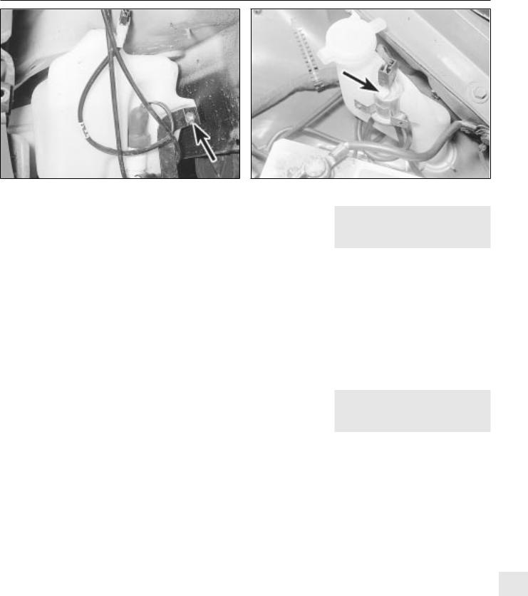
Body electrical systems 12• 15
41.17 Horn/washer fluid reservoir support bracket securing bolt |
43.1 Headlamp washer fluid non-return valve (arrowed) |
(arrowed) - model with headlamp wash |
|
41 Washer fluid reservoir - |
2 |
removal and refitting |
|
|
|
1 Disconnect the battery negative lead.
Models without headlamp wash
Removal
2 Disconnect the wiring from the washer pump.
3Disconnect the washer fluid hose from the pump. Be prepared for fluid spillage.
4Remove the screw(s) securing the reservoir to the body, and withdraw the reservoir.
Refitting
5 Refitting is a reversal of removal.
Models with headlamp wash
Removal
6 On models with headlamp wash, the reservoir is in two sections, the upper section, which can be removed from the engine compartment, and the lower section, which must be removed from under the wheel arch.
7Disconnect the wiring from the headlamp wash non-return valve in the top of the reservoir.
8Disconnect the washer fluid hoses from the non-return valve. Be prepared for fluid spillage.
9Remove the screw securing the upper section of the reservoir to the wing panel.
10Loosen the plastic collar securing the upper section of the reservoir to the lower section, then withdraw the upper section of the reservoir from the engine compartment.
11To remove the lower section of the reservoir, continue as follows.
12Apply the handbrake, then jack up the front of the vehicle, and support on axle
stands (see “ Jacking and Vehicle Support” ) positioned under the body side members.
13 Remove the securing screws, and withdraw the plastic cover from the
bumper/front wing to expose the lower section of the reservoir.
14Remove the horns, (Section 22).
15Remove the wheel arch liner, (Chapter 11).
16Disconnect the wiring and the fluid hoses from the washer pump. Be prepared for fluid spillage.
17Unscrew the bolts securing the horn/reservoir support bracket and the
reservoir to the body, then withdraw the bracket and the reservoir (see illustration).
Refitting
18 Refitting is a reversal of removal.
42 Washer pump - removal and |
2 |
refitting |
|
|
|
1 Disconnect the battery negative lead.
Models without headlamp wash
Removal
2 Disconnect the wiring and the fluid hose from the pump. Be prepared for fluid spillage. 3 Pull the pump from the reservoir, being prepared for fluid spillage if the reservoir still contains fluid.
4 Examine the condition of the sealing grommet, and renew if necessary, and clean the gauze filter at the end of the pump pick-up tube.
Refitting
5 Refitting is a reversal of removal.
Models with headlamp wash
6Apply the handbrake, then jack up the front of the vehicle, and support on axle stands positioned under the body side members.
7Remove the securing screws, and withdraw the plastic cover from the bumper/front wing to expose the lower section of the fluid reservoir.
8Remove the wheel arch liner, (Chapter 11).
9Proceed as described in paragraphs 2 to 5 inclusive.
43 Headlamp washer fluid |
2 |
non-return valve - removal |
|
and refitting |
Removal
1The valve is located on a bracket attached
to the upper section of the washer fluid reservoir (see illustration).
2Disconnect the battery negative lead.
3Disconnect the wiring and the fluid hoses from the valve. Be prepared for fluid spillage.
4Remove the screw securing the valve bracket to the reservoir, and withdraw the valve.
Refitting
5 Refitting is a reversal of removal.
44Electric window components 3
- removal and refitting
Note: Whenever any of the electric window components are removed, after refitting the components, the electric window controls must be programmed, as described in Section 45.
1 Disconnect the battery negative lead.
Rear door-mounted switches
Removal
2 Prise the plastic surround from the door interior handle.
3 Carefully prise the switch from its location, and disconnect the wiring plug.
Refitting
4 Refitting is a reversal of removal, but make 12 sure that the wiring is routed so that it does
not foul the electric window or lock operating components.
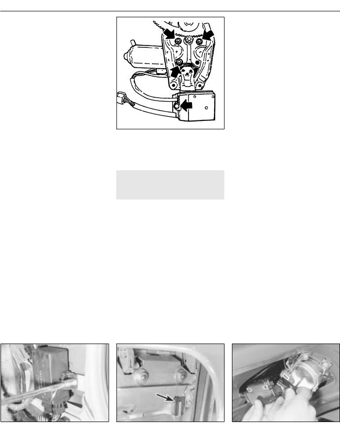
12• 16 Body electrical systems
Centre console-mounted switches
Removal
5 The switches must be removed as a complete assembly, and cannot be dismantled. If one of the switches is faulty, the complete assembly must be renewed.
6 Remove the rear section of the centre console, as described in Chapter 11.
7 Release the securing clips, and withdraw the switch assembly through the top of the centre console.
Refitting
8 Refitting is a reversal of removal.
Operating motors
9 Remove the door window regulator, described in Chapter 11.
10To remove the motor assembly from front door window regulator, unscrew three motor securing nuts, and the single screw securing the pulse pick-up unit to the regulator assembly. Withdraw the motor, complete with the pulse pick-up unit. Note that if the motor or pick-up unit is/are faulty,
the two components must be renewed as an assembly, as no spare parts are available (see illustration).
11The motor assembly fitted to the rear door window regulator is an integral part of the regulator, and no attempt should be made at dismantling. If faulty, the complete motor/regulator assembly must be renewed, as no spares are available.
45 Electric window controls - |
1 |
programming |
|
|
|
1Whenever the battery is disconnected, or any of the electric window components are removed, on completion of work, the electric window controls must be programmed as follows.
2Close all doors, and switch on the ignition.
3Close one of the windows by pressing the relevant operating switch. Press and hold the switch for a further five seconds after the relevant window has fully closed.
44.10 Front door electric window motor securing nuts and pulse pick-up securing screw (arrowed)
4 Repeat the procedure for the remaining window(s).
46 Central door locking |
3 |
components - removal and |
|
refitting |
1 Disconnect the battery negative lead.
Electronic control module
Removal
2 The module is mounted in the driver’s footwell, behind the side trim panel.
3 Remove the driver’s footwell side trim panel, as described in Chapter 11.
4Unscrew the two securing nuts, and lift the module from the body panel (see illustration).
5Depress the retaining clip to release the wiring plug, then withdraw the module.
Refitting
6 Refitting is a reversal of removal.
Operating switch
Removal
7 The operating switch takes the form of a microswitch, mounted inside the door at the rear of the exterior handle assembly.
8 Remove the door inner trim panel, as described in Chapter 11.
9 Peel back the plastic insulating sheet sufficiently to gain access to the exterior handle.
10 Unclip the microswitch from the rear edge of the exterior handle assembly, and disconnect the switch wiring plug from the
door wiring harness, then withdraw the switch
(see illustration).
Refitting
11 Refitting is a reversal of removal.
Door lock operating motor
Removal
12Remove the door lock, as described in Chapter 11.
13Disconnect the lock operating rod from the motor.
14Remove the two securing screws, and withdraw the motor from the lock assembly.
Refitting
15 Refitting is a reversal of removal.
Tailgate/boot lid lock operating motor
Removal
16 On Hatchback models, extract the securing screws and remove the rear tailgate trim panel.
17Remove the two securing screws, and manipulate the motor to disconnect the lock operating rod.
18Withdraw the motor and disconnect the wiring plug (see illustration).
Refitting
19 Refitting is a reversal of removal.
Fuel filler flap lock operating motor
Removal
20Remove the right-hand rear quarter trim panels, as described in Chapter 11.
21Disconnect the wiring plug from the rear of the motor (see illustration).
46.4 Unscrewing a central door locking |
microswitch (arrowed) in driver’s door |
the tailgate lock operating motor - |
control module securing nut |
||
|
|
Hatchback model |
 Loading...