


TX-SR600

AV Receiver
TX-SR700
TX-SR600
Instruction Manual
Contents
Before using 2
Facilities and connections 8
Thank you for purchasing the Onkyo AV Receiver.
Please read this manual thoroughly before making
connections and plugging in the unit. Following the
instructions in this manual will enable you to obtain
optimum performance and listening enjoyment from
your new AV Receiver. Please retain this manual for
future reference.
Setup and operation 36
Remote controller 63
Appendix 76
WARNING:
TO REDUCE THE RISK OF FIRE OR ELECTRIC SHOCK,
DO NOT EXPOSE THIS APPLIANCE TO RAIN OR
MOISTURE.
CAUTION:
TO REDUCE THE RISK OF ELECTRIC SHOCK, DO NOT
REMOVE COVER (OR BACK). NO USER-SERVICEABLE
PARTS INSIDE. REFER SERVICING TO QUALIFIED
SERVICE PERSONNEL.
Important Safeguards
WARNING
RISK OF ELECTRIC SHOCK
DO NOT OPEN
The lightning flash with arrowhead symbol, within an equilateral
triangle, is intended to alert the user to the presence of uninsulated
“dangerous voltage” within the product’s enclosure that may be of
sufficient magnitude to constitute a risk of electric shock to persons.
The exclamation point within an equilateral triangle is intended to
alert the user to the presence of important operating and maintenance
(servicing) instructions in the literature accompanying the appliance.
AVIS
RISQUE DE CHOC ELECTRIQUE
OUVRIR
NE PAS
1. Read Instructions – All the safety and operating instructions
should be read before the appliance is operated.
2. Retain Instructions – The safety and operating instructions
should be retained for future reference.
3. Heed Warnings – All warnings on the appliance and in the
operating instructions should be adhered to.
4. Follow Instructions – All operating and use instructions
should be followed.
5. Cleaning – Unplug the appliance from the wall outlet before
cleaning. The appliance should be cleaned only as recommended by the manufacturer.
6. Attachments – Do not use attachments not recommended by
the appliance manufacturer as they may cause hazards.
7. Water and Moisture – Do not use the appliance near water –for
example, near a bath tub, wash bowl, kitchen sink, or laundry
tub; in a wet basement; or near a swimming pool; and the like.
8. Accessories – Do not place the appliance on an unstable cart,
stand, tripod, bracket, or table. The appliance may fall, causing
serious injury to a child or adult, and serious damage to the
appliance. Use only with a cart, stand, tripod, bracket, or table
recommended by the manufacturer, or sold with the appliance.
Any mounting of the appliance should follow the
manufacturer’s instructions, and
should use a mounting accessory
recommended by the manufacturer.
9. An appliance and cart combination should be moved with care.
Quick stops, excessive force, and
uneven surfaces may cause the
appliance and cart combination to
overturn.
10. Ventilation – Slots and openings in the cabinet are provided
for ventilation and to ensure reliable operation of the appliance
and to protect it from overheating, and these openings must not
be blocked or covered. The openings should never be blocked
by placing the appliance on a bed, sofa, rug, or other similar
surface. The appliance should not be placed in a built-in installation such as a bookcase or rack unless proper ventilation is
provided. There should be free space of at least 20 cm (8 in.)
and an opening behind the appliance.
11. Power Sources – The appliance should be operated only from
the type of power source indicated on the marking label. If you
are not sure of the type of power supply to your home, consult
your appliance dealer or local power company.
12. Grounding or Polarization – The appliance may be equipped
with a polarized alternating current line plug (a plug having one
blade wider than the other). This plug will fit into the power
outlet only one way. This is a safety feature. If you are unable to
insert the plug fully into the outlet, try reversing the plug. If the
plug should still fail to fit, contact your electrician to replace
your obsolete outlet. Do not defeat the safety purpose of the
polarized plug.
PORTABLE CART WARNING
S3125A
13. Power-Cord Protection – Power-supply cords should be
routed so that they are not likely to be walked on or pinched by
items placed upon or against them, paying particular attention
to cords at plugs, convenience receptacles, and the point where
they exit from the appliance.
14. Outdoor Antenna Grounding – If an outside antenna or cable
system is connected to the appliance, be sure the antenna or
cable system is grounded so as to provide some protection
against voltage surges and built-up static charges. Article 810
of the National Electrical Code, ANSI/NFPA 70, provides information with regard to proper grounding of the mast and supporting structure, grounding of the lead-in wire to an antennadischarge unit, size of grounding conductors, location of antenna-discharge unit, connection to grounding electrodes, and
requirements for the grounding electrode. See Figure 1.
15. Lightning – For added protection for the appliance during a
lightning storm, or when it is left unattended and unused for
long periods of time, unplug it from the wall outlet and disconnect the antenna or cable system. This will prevent damage to
the appliance due to lightning and power-line surges.
16. Power Lines – An outside antenna system should not be lo-
cated in the vicinity of overhead power lines or other electric
light or power circuits, or where it can fall into such power lines
or circuits. When installing an outside antenna system, extreme
care should be taken to keep from touching such power lines or
circuits as contact with them might be fatal.
17. Overloading – Do not overload wall outlets, extension cords,
or integral convenience receptacles as this can result in a risk
of fire or electric shock.
18. Object and Liquid Entry – Never push objects of any kind
into the appliance through openings as they may touch dangerous voltage points or short-out parts that could result in a fire or
electric shock. Never spill liquid of any kind on the appliance.
19. Servicing – Do not attempt to service the appliance yourself as
opening or removing covers may expose you to dangerous voltage or other hazards. Refer all servicing to qualified service
personnel.
20. Damage Requiring Service – Unplug the appliance form the
wall outlet and refer servicing to qualified service personnel
under the following conditions:
A. When the power-supply cord or plug is damaged,
B. If liquid has been spilled, or objects have fallen into the
appliance,
C. If the appliance has been exposed to rain or water,
D. If the appliance does not operate normally by following the
operating instructions. Adjust only those controls that are
covered by the operating instructions as an improper ad-
justment of other controls may result in damage and will
often require extensive work by a qualified technician to
restore the appliance to its normal operation,
E. If the appliance has been dropped or damaged in any way,
and
F. When the appliance exhibits a distinct change in perfor-
mance – this indicates a need for service.
2

21. Replacement Parts – When replacement parts are required, be
sure the service technician has used replacement parts specified
by the manufacturer or have the same characteristics as the
original part. Unauthorized substitutions may result in fire,
electric shock, or other hazards.
22. Safety Check – Upon completion of any service or repairs to the
appliance, ask the service technician to perform safety checks to
determine that the appliance is in proper operation condition.
23. Wall or Ceiling Mounting – The appliance should be mounted
to a wall or ceiling only as recommended by the manufacturer.
24. Heat – The appliance should be situated away from heat
sources such as radiators, heat registers, stoves, or other appliances (including amplifiers) that produce heat.
25. Liquid Hazards – The appliance shall not be exposed to dripping or splashing and no objects filled with liquids, such as
vases shall be placed on the appliance.
Precautions
FIGURE 1:
EXAMPLE OF ANTENNA GROUNDING AS PER NATIONAL
ELECTRICAL CODE, ANSI/NFPA 70
ANTENNA
LEAD IN
WIRE
GROUND
CLAMP
ANTENNA
DISCHARGE UNIT
(NEC SECTION 810-20)
ELECTRIC
SERVICE
EQUIPMENT
NEC – NATIONAL ELECTRICAL CODE
S2898A
GROUNDING CONDUCTORS
(NEC SECTION 810-21)
GROUND CLAMPS
POWER SERVICE GROUNDING
ELECTRODE SYSTEM
(NEC ART 250, PART H)
1. Recording Copyright
Recording of copyrighted material for other than personal use is
illegal without permission of the copyright holder.
2. AC Fuse
The fuse is located inside the chassis and is not user-serviceable. If power
does not come on, contact your Onkyo authorized service station.
3. Care
From time to time you should wipe the front and rear panels and the
cabinet with a soft cloth. For heavier dirt, dampen a soft cloth in a
weak solution of mild detergent and water, wring it out dry, and
wipe off the dirt. Following this, dry immediately with a clean
cloth. Do not use rough material, thinners, alcohol or other chemical solvents or cloths since these could damage the finish or remove
the panel lettering.
4. Power
WARNING
BEFORE PLUGGING IN THE UNIT FOR THE FIRST TIME,
READ THE FOLLOWING SECTION CAREFULLY.
The voltage of the available power supply differs according to
country or region. Be sure that the power supply voltage of the area
where this unit will be used meets the required voltage (e.g., AC
230 V, 50 Hz or AC 120 V, 60 Hz) written on the rear panel.
Worldwide models are equipped with a voltage selector to conform
to local power supplies. Be sure to set this switch to match the voltage of the power supply in your area before plugging in the unit.
For British models
Replacement and mounting of an AC plug on the power supply cord
of this unit should be performed only by qualified service personnel.
IMPORTANT
The wires in the mains lead are coloured in accordance with the
following code:
Blue : Neutral
Brown : Live
As the colours of the wires in the mains lead of this apparatus may
not correspond with the coloured markings identifying the terminals in your plug, proceed as follows:
The wire which is coloured blue must be connected to the terminal
which is marked with the letter N or coloured black.
The wire which is coloured brown must be connected to the terminal which is marked with the letter L or coloured red.
IMPORTANT
A 5 ampere fuse is fitted in this plug. Should the fuse need to be
replaced, please ensure that the replacement fuse has a rating of 5
amperes and that it is approved by ASTA or BSI to BS1362. Check
for the ASTA mark or the BSI mark on the body of the fuse.
IF THE FITTED MOULDED PLUG IS UNSUITABLE FOR THE
SOCKET OUTLET IN YOUR HOME THEN THE FUSE
SHOULD BE REMOVED AND THE PLUG CUT OFF AND DISPOSED OF SAFELY. THERE IS A DANGER OF SEVERE
ELECTRICAL SHOCK IF THE CUT OFF PLUG IS INSERTED
INTO ANY 13 AMPERE SOCKET.
If in any doubt, consult a qualified electrician.
For U.S. models
Note to CATV system installer:
This reminder is provided to call the CATV system installer’s attention to Section 820-40 of the NEC which provides guidelines for
proper grounding and, in particular, specifies that the cable ground
shall be connected to the grounding system of the building, as close
to the point of cable entry as practical.
FCC Information for User
CAUTION:
The user changes or modifications not expressly approved by the
party responsible for compliance could void the user’s authority to
operate the equipment.
NOTE:
This equipment has been tested and found to comply with the limits
for a Class B digital device, pursuant to Part 15 of the FCC Rules.
These limits are designed to provide reasonable protection against
harmful interference in a residential installation. This equipment
generates, uses and can radiate radio frequency energy and, if not
installed and used in accordance with the instructions, may cause
harmful interference to radio communications. However, there is
no guarantee that interference will not occur in a particular installation. If this equipment does cause harmful interference to radio or
television reception, which can be determined by turning the equipment off and on, the user is encouraged to try to correct the interference by one or more of the following measures:
• Reorient or relocate the receiving antenna.
• Increase the separation between the equipment and receiver.
• Connect the equipment into an outlet on a circuit different from
that to which the receiver is connected.
• Consult the dealer or an experienced radio/TV technician for
help.
For Canadian models
NOTE: THIS CLASS B DIGITAL APPARATUS COMPLIES
WITH CANADIAN ICES-003.
For models having a power cord with a polarized plug:
CAUTION: TO PREVENT ELECTRIC SHOCK, MATCH
WIDE BLADE OF PLUG TO WIDE SLOT, FULLY INSERT.
Modèle pour les Canadien
REMARQUE: CET APPAREIL NUMÉRIQUE DE LA
CLASSE B EST CON-FORME À LA NORME NMB-003 DU
CANADA.
Sur les modèles dont la fiche est polarisée:
ATTENTION: POUR ÉVITER LES CHOCS ÉLECTRIQUES,
INTRODUIRE LA LAME LA PLUS LARGE DE LA FICHE
DANS LA BORNE CORRESPONDANTE DE LA PRISE ET
POUSSER JUSQU’AU FOND.
3
Contents
Before using
Important Safeguards......................................... 2
Precautions ......................................................... 3
Contents .............................................................. 4
Features ...............................................................6
Supplied accessories ......................................... 7
Before using this unit......................................... 7
Setting the voltage selector
(Worldwide models only) ......................................... 7
Installing the remote controller batteries ......................... 7
Using the remote controller.............................................. 7
Facilities and connections
Front panel facilities........................................... 8
Front panel .......................................................... 8
Front panel display ........................................... 11
Remote controller .............................................12
Connections ...................................................... 14
Connections (TX-SR700/700E) ........................ 16
Connecting your audio components .............................. 16
Connecting your video components .............................. 17
12V TRIGGER ZONE 2 terminal.................................. 21
PRE OUT ........................................................................ 21
Operating components not reached by the
remote controller signals (IR IN) (TX-SR700/
700E only) ..................................................... 22
If the remote controller signal does not reach the TX-
SR700/700E remote sensor .................................... 22
Connecting the remote zone (Zone 2) speakers
(TX-SR700/700E only).................................. 23
When using the ZONE 2 SPEAKERS terminals........... 23
When using the ZONE 2 PRE OUT terminals .............. 23
AC OUTLETS ................................................................ 29
REMOTE CONTROL ............................................. 29
Connections (TX-SR600/600E) ........................ 24
Connecting your audio components .............................. 24
Connecting your video components .............................. 25
AC OUTLETS ................................................................ 29
REMOTE CONTROL ............................................. 29
Connecting speakers ....................................... 30
Standard speaker setup for surround sound ................... 30
Minimum speaker configuration for
surround sound playback ........................................ 30
Speaker placement .......................................................... 30
Using the speaker labels ................................................. 30
Connecting speakers ....................................................... 31
Connecting the speaker cable ......................................... 31
Connecting a subwoofer ................................................. 31
Connecting to the SPEAKERS B terminals
(TX-SR600/600E only) .......................................... 31
Connecting the power ...................................... 33
Turning on the power ..................................................... 33
Turning on the power from the remote controller ........ 33
Connecting antennas ....................................... 34
Assembling the AM loop antenna.................................. 34
Connecting the AM antenna cable ................................. 34
Connecting the included antennas ................................. 34
Connecting an FM outdoor antenna............................... 35
Connecting an AM outdoor antenna .............................. 35
Directional linkage ......................................................... 35
Connecting the antenna cable to the 75/300 Ω antenna
adapter (For all models other than USA &
Canadian models and European models) ............... 35
Setup and operation
Configuring the speakers ................................ 36
Displaying the Main Menu ............................................ 36
Speaker Configuration ................................................... 36
Setting the speaker distance from
your normal listening position ................................ 38
Calibrating the speaker levels ........................................ 38
Buttons used for navigating through the menus ............ 39
Listening to Radio Broadcasts........................ 40
Tuning into a radio station ............................................. 40
Listening to a stereo radio station (FM mode) .............. 40
Presetting a radio station ................................................ 41
Selecting a preset radio station ...................................... 41
Erasing a preset radio station ......................................... 41
Listening to RDS broadcasts (European models
only) .............................................................. 42
Listening to RDS broadcasts .......................................... 42
PTY program types in Europe........................................ 42
Displaying Radio Text (RT) ........................................... 43
Performing a PTY scan .................................................. 43
Performing a TP scan ..................................................... 43
4
Contents
Selecting an Audio Component ...................... 44
Basic operation (TX-SR700/700E) ................................ 44
Basic operation (TX-SR600/600E) ................................ 45
Selecting speakers (SPEAKERS A, B)
(TX-SR600/600E only) .......................................... 45
Selecting the type of audio input signal......................... 46
Temporarily changing the speaker output levels ........... 46
To change the display of the input source
from TAPE to MD................................................... 46
Using the sleep time (remote controller only) ............... 47
Listening with headphones............................................. 47
Enjoying DVD multichannel audio playback ................ 47
Switching the display ..................................................... 48
Temporarily turning off the sound ................................. 48
Listening Modes ............................................... 49
Selecting a listening mode ............................................. 51
Original filter (CinemaFILTER) loading for movies .... 52
Input Setup ........................................................ 53
OSD Setup and Other Settings........................ 56
OSD Setup ...................................................................... 56
Preference ....................................................................... 56
Audio Adjust...................................................... 57
Enjoying music in the remote zone
(TX-SR700/700E only).................................. 60
Using the buttons on the TX-SR700/700E .................... 60
Using the remote controller............................................ 60
Adjusting the volume for the remote zone .................... 60
Recording a source (TX-SR700/700E) ............ 61
To record the input source signal you are currently
watching or listening to .......................................... 61
To record an input source signal different from that you
are currently watching or listening to..................... 61
Recording a source (TX-SR600/600E) ............ 62
To record the input source signal you are currently
watching or listening to .......................................... 62
Entering a pre-programming code.................. 67
Learning a pre-programming code................................. 67
Pre-programming codes ................................................. 68
Operating your programmed
remote controller ......................................... 69
DVD MODE (DVD Player Mode) ................................ 69
VCR MODE (VCR Mode) ............................................. 69
TV MODE (TV Mode) ................................................... 69
Programming the commands of remote
controllers for other devices into the
remote controller ......................................... 70
Programming procedure ................................................. 70
Erasing the programmed command from one button .... 72
Erasing all the commands programmed under a MODE
button....................................................................... 72
Using the macro function ................................ 73
What is the macro function? .......................................... 73
Programming the macro ................................................. 73
Executing the macro ....................................................... 73
Erasing a macro from the MACRO 1 (or 2) button ...... 74
Erasing all commands and macros that have been
programmed ............................................................ 74
Macro mode programming memo.................................. 75
Appendix
Troubleshooting guide .....................................76
POWER .......................................................................... 76
SPEAKERS .................................................................... 76
FM/AM TUNER............................................................. 76
VIDEO and AUDIO ....................................................... 77
REMOTE CONTROLLER ............................................ 77
OTHER ........................................................................... 77
If one of the messages shown below appears ................ 78
Specifications (TX-SR700/700E) ..................... 79
Specifications (TX-SR600/600E)....... back cover
Remote controller
Using remote controller ................................... 63
Overview ........................................................................ 63
Calling up a preset radio station .................................... 63
Controlling an Onkyo cassette tape deck ...................... 63
Controlling an Onkyo CD player ................................... 64
Controlling an Onkyo DVD player ................................ 65
Controlling an Onkyo MD recorder............................... 66
VCR and TV MODE buttons ......................................... 66
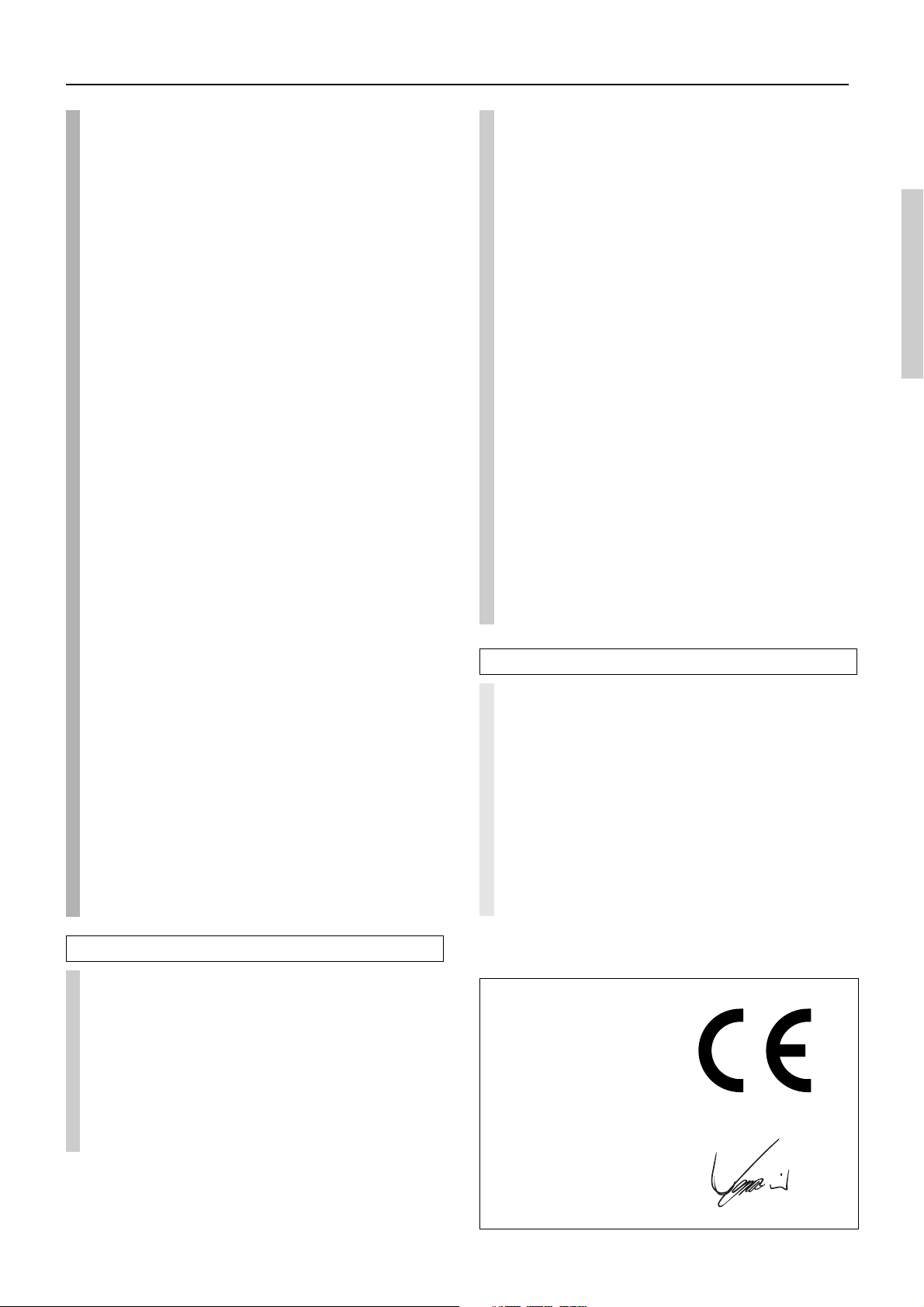
Declaration of Conformity
We,
ONKYO EUROPE
ELECTRONICS GmbH
INDUSTRIESTRASSE 20
82110 GERMERING,
GERMANY
declare in own responsibility, that the ONKYO product described
in this instruction manual is in compliance with the corresponding
technical standards such as EN60065, EN55013, EN55020 and
EN61000-3-2, -3-3.
GERMERING, GERMANY
I. MORI
ONKYO EUROPE ELECTRONICS GmbH
5

Features
TX-SR700/700E
Amplifier Features
■ 100 W × 2 (Front)/ 100 W (Center)/ 100 W × 2
(Surround)/ 100 W (Surround Back) at 8 ohms, 20 Hz 20 kHz, 0.08 % THD (FTC rated)
■ 130 W × 2 (Front)/ 130 W (Center)/ 130 W × 2
(Surround)/ 130 W (Surround Back) at 6 ohms
(DIN)
■ 160 W × 2 (Front)/ 160 W (Center)/ 160W × 2
(Surround)/ 160 W (Surround Back) at 6 ohms
(JEITA)
■ Wide Range Amplifier Technology (WRAT)
■ Powered Zone 2 Capability
■ State-of-the-art linear PCM 192 kHz/24-bit
DACs for L/R channels
■ Optimum gain volume circuitry
Audio/Video Features
■ Dolby®* Digital, Dolby Digital EX, Dolby Pro
Logic II
■ DTS, DTS-ES Extended Surround, DTS Neo:6
■ Non-Scaling Configuration
■ CinemaFILTER
■ “Easy-set” speaker configuration
■ Pure Audio Mode
■ Crossover Adjustment (80/100/120 Hz)
■ Onscreen graphical displays
■ Digital Outputs (1 coaxial, 1 optical)
■ 2 component video inputs and 1 output
■ 3 Assignable digital inputs (1 coaxial, 2 optical)
■ 5 S-Video inputs and 3 outputs
■ Front panel A/V, S-Video, Optical inputs
■ Multi channel input for DVD-Audio
■ Rec out selector and Zone 2 selector
■ Pre-out terminals for Front L/R, Center,
Surround L/R, Surround Back, Subwoofer and
Zone 2 L/R
■ Color-coded speaker terminals
TX-SR600/600E
Amplifier Features
■ 80 W × 2 (Front)/ 80 W (Center)/ 80 W × 2 (Surround)/
80 W (Surround Back) at 8 ohms, 20 Hz - 20 kHz,
0.08 % THD (FTC rated)
■ 115 W × 2 (Front)/ 115 W (Center)/ 115 W × 2
(Surround)/ 115 W (Surround Back) at 6 ohms (DIN)
■ 145 W × 2 (Front)/ 145 W (Center)/ 145 W × 2
(Surround)/ 145 W (Surround Back) at 6 ohms (JEITA)
■ Wide Range Amplifier Technology (WRAT)
■ State-of-the-art linear PCM 192 kHz/24-bit
DACs for L/R channels
■ Optimum gain volume circuitry
Audio/Video Features
■ Dolby Digital, Dolby Digital EX, Dolby Pro Logic II
■ DTS, DTS-ES Extended Surround, DTS Neo:6
■ Non-Scaling Configuration
■ CinemaFILTER
■ “Easy-set” speaker configuration
■ Crossover Adjustment (80/100/120 Hz)
■ Onscreen graphical displays
■ Optical Digital Output
■ 2 component video inputs and 1 output
■ 3 Assignable digital inputs (1 coaxial, 2 optical)
■ 5 S-Video inputs and 2 outputs
■ Front panel A/V, S-Video, Optical inputs
■ Multi channel input for DVD-Audio
■ Pre-out terminal for Subwoofer
■ Color-coded speaker terminals
■ A/B speaker drive
FM/AM Tuner Features
■ 40 FM/AM random presets
■ FM auto tuning
■ RDS (European models) with PS/RT/PTY/TP
FM/AM Tuner Features
■ 40 FM/AM random presets
■ FM auto tuning
■ RDS (European models) with PS/RT/PTY/TP
Other Performance Features
■ IntelliVolume
■ Powerful backlit/preprogrammed learning
remote with macro and mode-key LEDs
■ 12V Trigger output for Zone 2
■ IR input terminal
6
Other Performance Features
■ IntelliVolume
■ Preprogrammed learning remote with macro and
mode-key LEDs
* Manufactured under license from Dolby Laboratories.
“Dolby,” “Pro Logic,” and the double-D symbol are trademarks of
Dolby Laboratories.
•“DTS,” “DTS-ES Extended Surround,” and “Neo:6” are trademarks of
Digital Theater Systems, Inc.
• Xantech is a registered trademark of Xantech Corporation.
• Niles is a registered trademark of Niles Audio Corporation.
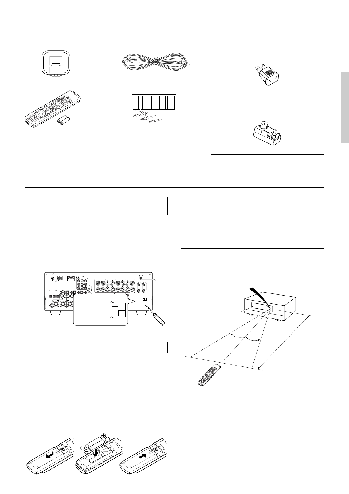
Supplied accessories
Check that the following accessories are supplied with the TX-SR700/700E/600/600E.
The following accessories may be available
depending on the area which it was purchased.
AM loop antenna × 1
R
C
4
8
2
M
Remote controller × 1
FM indoor antenna × 1
Left
Left
Left
Left
Left
Left
Front
Front
Front
Front
Right
Zone 2
Zone 2
/
/
SP-B
SP-B
Zone 2
Zone 2
/
/
Front
Left
Front
SP-B
Left
Front
Left
Front
Right
SP-B
Left
1
Speaker Cable
Left
Right
Right
Right
Right
Right
Zone 2
Zone 2
/
/
Center
Center
Surround
Surround
Surround
Surround
SP-B
SP-B
Surround Back
Surround Back
Zone 2
Zone 2
/
/
Right
SP-B
Right
Surround
Right
Center
Surround
Left
Surround Back
Left
Surround
Right
Center
Surround
Left
SP-B
Right
Surround Back
2
3
Speaker cable label × 1
TX-SR700/700E: RC-482M
TX-SR600/600E: RC-480M
Batteries (AA, R6 or UM-3) × 2
Before using this unit
Setting the voltage selector
(Worldwide models only)
Worldwide models are equipped with a voltage selector so that you
can set your TX-SR700/700E/600/600E to conform with local
power supplies. Be sure to set this switch to match the voltage of the
power supply in your area before plugging in the unit.
Determine the proper voltage for your area: 220-230 V or 120 V. If
the preset voltage is not correct for your area, insert a screwdriver
into the groove in the switch and slide the switch all the way to the
top (120 V) or bottom (220-230 V), whichever is appropriate.
27122974
FRONT
SPEAKERS
L
R
IR
IN
220-230 V
MODEL NO.
120 V
AV RECEIVER
CAUTION: SPEAKER IMPEDANCE
6 OHMS MIN. /SPEAKER
ZONE
2
SPEAKERS
L
R
L
PRE OUT
R
TX-SR700E
CENTER
SURROUND
SPEAKERS
SPEAKER
AC OUTLETS
SURROUND
BACK
ZONE 2
SURROUND
CENTER
FRONT
SPEAKER
SWITCHED
TOTAL 100W MAX.
L
120 V
R
VOLTAGE
SELECTOR
SURROUND
220-230 V
BACK
SUBWOOFER
PRE OUT
DIGITAL INPUT
2
ANTENNA
FM
AM
75
DIGITAL
COAXIAL
OUTPUT
OPTICAL
OPTICAL
1
COAXIAL
DIGITAL
INPUT
IN
OUT
IN
L
R
TAPE
CD
VIDEO 2
VIDEO 3
OUT
IN
IN
OUT
VIDEO 3
VIDEO 2
GND
COMPONENT VIDEO
INPUT 2
R
L
PHONO IN
VIDEO 1
OUT
IN
IN
OUT
IN
IN
VIDEO 1
VOLTAGE
SELECTOR
OUTPUT
INPUT 1
Y
P
B
REMOTE
CONTROL
P
R
DVD
MONITOR
ZONE 2
IN
OUT
12 V
TRIGGER
V
OUT
S
SURR
CENTER
FRONT
L
R
SUB
WOOFER
DVD
Left
Left
Left
Right
Right
Right
Right
Zone 2
Zone 2
Zone 2
Zone 2
Surround Back
Surround Back
Zone 2
Right
Zone 2
Left
Zone 2
Right
Zone 2
Left
Surround Back
Right
Surround Back
Right
Left
(Use this plug if the power cord plug of the TX-
SR700/700E/600/600E does not fit your AC outlet.
Shape may vary depending on the area which it
was purchased.)
75/300 Ω antenna adapter × 1
Notes:
• Do not mix new batteries with old batteries or different kinds of batteries.
• To avoid corrosion, remove the batteries if the remote controller
will not be used for a long time.
• Remove dead batteries immediately to avoid damage from corrosion.
If the remote controller does not operate smoothly, remove the old
batteries and replace them both with two new AA batteries.
Using the remote controller
Point the remote controller toward the remote control sensor. The
STANDBY indicator lights up when the unit receives a signal from
the remote controller.
Conversion plug × 1
Remote control sensor
STANDBY indicator
TX-SR700/700E/
600/600E
Installing the remote controller batteries
1. Remove the battery compartment cover by pressing it
and sliding it in the direction shown by the arrow
below.
2. Insert two AA (R6 or UM-3) batteries into the battery
compartment. Carefully follow the polarity diagram
(positive (+) and negative (–) symbols) inside the
battery compartment.
3. After the batteries are installed and seated correctly,
replace the compartment cover.
321
30˚
30˚
Approx. 16 feet
(5 meters)
R
C
4
8
2
M
Notes:
• Make sure that the remote control sensor is not subject to strong
light such as direct sunlight or inverted fluorescent light for it
may prevent proper operation of the remote controller.
• Using another remote controller in the same room or using the
TX-SR700/700E/600/600E near equipment that uses infrared
rays may cause operational interference.
• Do not put objects on the remote controller. Its buttons may be
pressed by mistake and drain the batteries.
• Make sure the audio rack doors do not have colored glass.
Placing the TX-SR700/700E/600/600E behind such doors may
prevent proper remote controller operation.
• If there is any obstacle between the remote controller and the
remote control sensor, the remote controller will not operate.
7
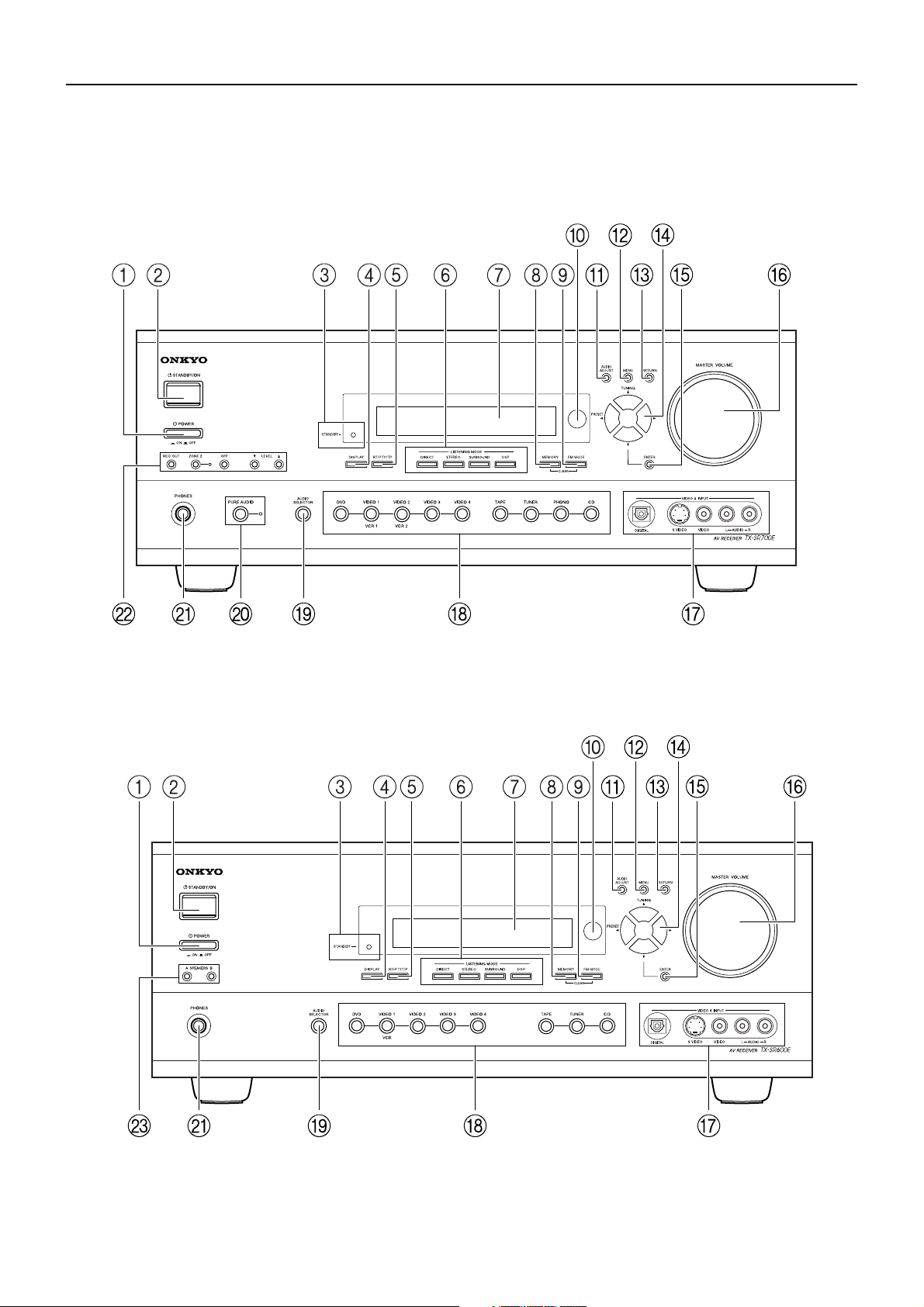
Front panel facilities
Here is an explanation of the controls and displays on the front panel of the TX-SR700E/600E.
Front panel
<TX-SR700E>
<TX-SR600E>
8
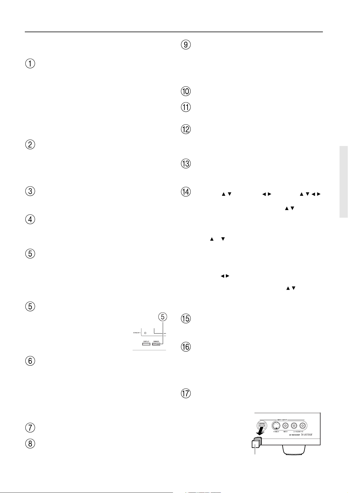
Front panel facilities
For further operational instructions, see the pages indicated in
brackets [ ].
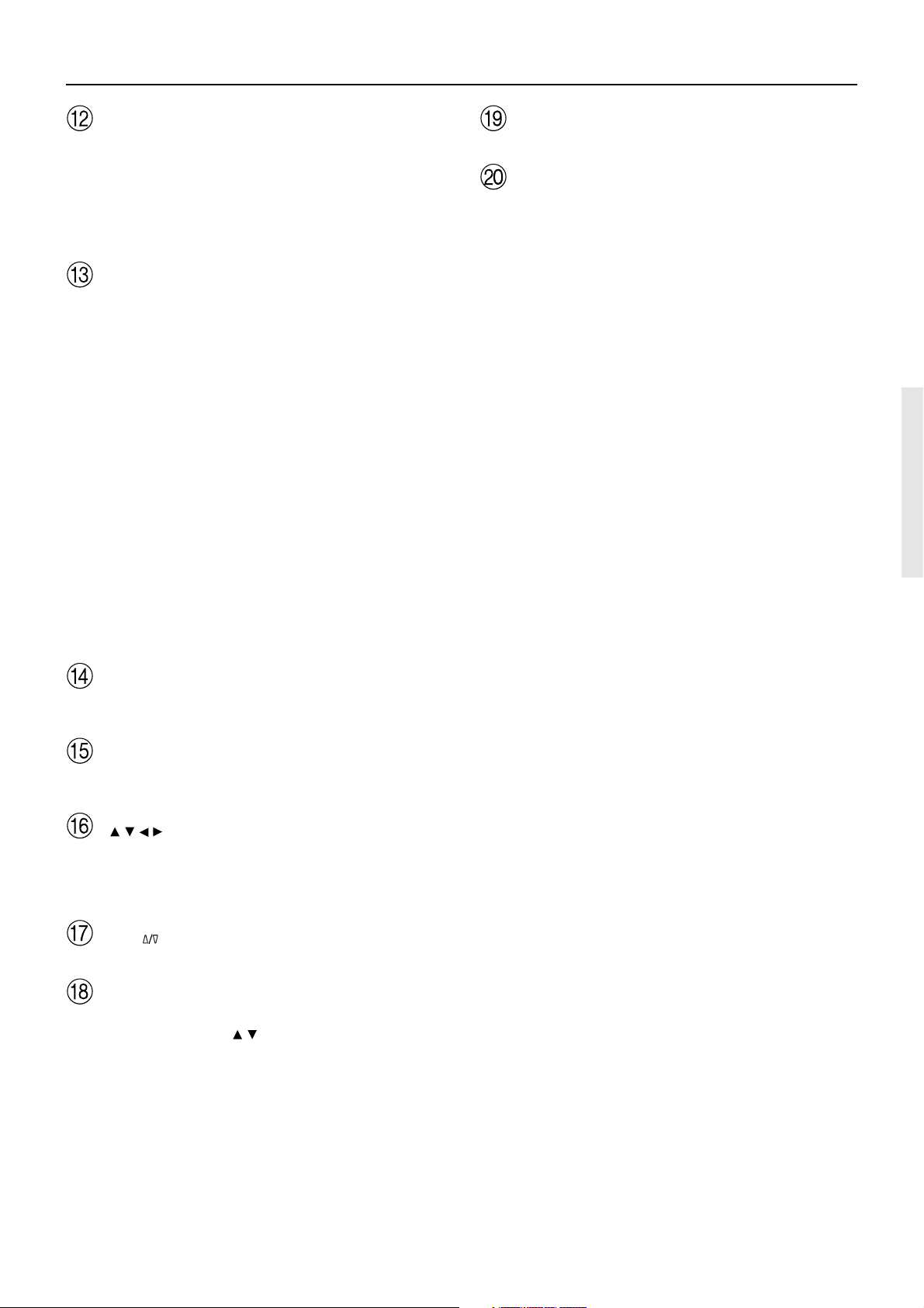
POWER switch (for all models other than USA and
Canadian models) [33]
Press to turn on and off the main power supply for the TX-SR700/
700E/600/600E. When the TX-SR700/700E/600/600E is turned on
with the POWER switch, the STANDBY indicator lights.
• Before turning on the power, check to make sure that all cords
are properly connected.
• When the power is turned on, a sudden surge of current will
occur that may adversely affect the operation of other devices.
To prevent this, do not plug the TX-SR700/700E/600/600E into
the same circuit used by sensitive equipment, e.g., computers.
STANDBY/ON button [33]
If pressed with the POWER switch turned on (with the receiver
plugged in for US models), the TX-SR700/700E/600/600E turns on
and the display lights up. If pressed again, the TX-SR700/700E/600/
600E returns to the standby state. In the standby state, the display is
turned off and the TX-SR700/700E/600/600E cannot be operated.
STANDBY indicator [7, 33]
Lights when the TX-SR700/700E/600/600E is in the standby state
and when a signal is received from the remote controller.
DISPLAY button [48]
Press to display information about the current input source signal.
Each time you press the display button, the screen changes to show
you different information concerning the input signal.
RT/PTY/TP (European models only) button [43]
This button is only available on European models. Press this button
to tune into the Radio Data System (RDS) for FM broadcasting. RDS
was developed within the European Broadcasting Union (EBU) and
is available in most European countries. Each time the button is
pressed, the display changes from RT (radio text) to PTY (program
type) to TP (traffic program) and then back to RT again.
DIMMER button
Press to set the brightness of the front
display. There are 3 settings available:
normal, dark, and very dark.
• The brightness of the front display can
also be performed using the remote
controller.
LISTENING MODE buttons [49-51]
Press these buttons to select a listening mode for the current input
source. Press the DIRECT, STEREO, and SURROUND buttons to
select a listening mode directly. Press the DSP button to select any of
the possible listening modes for the input source currently selected.
Note:
During playback of a multichannel source, press the DIRECT button
to turn off the tone control and the SURROUND button to turn on
the tone control. [48]
Front display
MEMORY button [41]
Press to assign the radio station that you are currently tuned into to a
preset channel or press to delete a previously preset station.
FM MODE button [40]
Press to change the stereo mode from AUTO to MONO and vice
versa. Each time this button is pressed, the AUTO indication turns
on and off indicating the current mode. If you are listening to an FM
radio station in stereo and the sound cuts out or there is a great deal of
noise, switch from AUTO to MONO.
Remote control sensor [7]
AUDIO ADJUST button [57]
Press to adjust the sound quality and the listening mode.
MENU button [36]
Press to enter the Setup Menu. The OSD Menu will appear on the TV
monitor as well as the front display on the TX-SR700/700E/600/
600E.
RETURN button [36]
When in the Setup Menu, press to go back one level. If pressed while
at the Main Menu, you will exit the Setup Menu.
TUNING / , PRESET / , cursor ( / / / )
buttons [36, 40, 41]
To tune into a radio station, press the TUNING
tuner frequency is displayed in the front display and it can be changed
in 50-kHz increments for FM and 10-kHz (or 9-kHz) increments for
AM.
When FM is selected as the input source, you can hold down either
the TUNING
search feature. It will search for a station in the direction of the
button you pressed and stop when it tunes into one. When navigating
through the menu settings, these buttons move the cursor up or down
(or change the highlighted item).
To select a radio station that was stored using the MEMORY button,
press the PRESET
When navigating through the menu settings, these buttons select the
value or item that you selected with the TUNING
When you press the MENU button, the TUNING and PRESET
buttons become cursor buttons to be used for Setup Menu
operations.
Press to display the screen for the item that is selected in the Setup
Menu.
TX-SR600/600E:
Use to control the volume.
TX-SR700/700E:
Use to control the volume in the main zone. The volume for the
remote zone (Zone 2) is independent.
For connecting a video camera or game device.
The VIDEO 4 INPUT (DIGITAL)
jack is provided with a protective
cap. When using this jack, remove
the protective cap and keep it
safely. When not using this jack,
replace the protective cap.
or button and then release it to activate the auto-
/ buttons.
ENTER button [36]
MASTER VOLUME dial [44, 45]
VIDEO 4 INPUT terminals [21, 28]
Protective cap
/ buttons. The
/ buttons.
9

Front panel facilities
Input source buttons (DVD, VIDEO 1–4, TAPE,
TUNER, PHONO (TX-SR700/700E only), and CD)
[44, 45, 53]
TX-SR600/600E:
These buttons are used to select the input source.
TX-SR700/700E:
Press these buttons to select the input source for the main zone.
To select the input source for the remote zone (Zone 2) or recording
out (Rec Out), first press the ZONE 2 or REC OUT button, and then
press the desired input source button. The input channel with its
indicator lit red is output to REC OUT and the one with its indicator
lit green is output to ZONE 2.
AUDIO SELECTOR button [47]
Press to select the type of audio input signal.
PURE AUDIO button and indicator (TX-SR700/700E
only) [49, 51]
Press to select the Pure Audio mode.
The PURE AUDIO indicator lights during pure audio playback.
PHONES jack [47]
This is a standard stereo jack for connecting stereo headphones.
REC OUT, ZONE 2, OFF, LEVEL / buttons, and
ZONE 2 indicator (TX-SR700/700E only) [60, 61]
The REC OUT and ZONE 2 buttons allow you to use the TX-SR700/
700E to output to a remote zone (Zone 2) or to another component
for recording (Rec Out). Press the REC OUT button to output the
audio and video signals to a recording component for recording.
Press the ZONE 2 button to enjoy the output from the TX-SR700/
700E in a different room, which is referred to as the remote zone
(Zone 2). When either button is pressed, the currently selected input
source for recording or outputting to the remote zone is displayed in
the front panel display. If “SOURCE” is displayed, then the same
input source as that selected for the main zone will be output.
To select an input source, press the desired button (REC OUT or
ZONE 2) and then press one of the input source button within 5
seconds. That source will be output for recording or viewing in the
remote zone.
To set the output to the source channel, press the desired button
(REC OUT or ZONE 2) twice in succession. To turn off the output,
press the OFF button. The ZONE 2 indicator lights when a signal is
output to the remote zone (Zone 2). When the ZONE 2 indicator is
off, then either output to the remote zone is turned off or Rec Out is
selected. Press the LEVEL
adjusting the volume in the remote zone (Zone 2).
Note:
The Rec Out and Zone 2 buttons use the same circuit and therefore
cannot be used at the same time. When REC OUT is selected,
nothing is output to Zone 2. When ZONE 2 is selected, REC OUT is
automatically fixed to SOURCE.
/ buttons to enter the mode for
SPEAKERS A/B buttons (TX-SR600/600E only) [45]
Press these buttons to turn on and off speakers systems A and B.
10
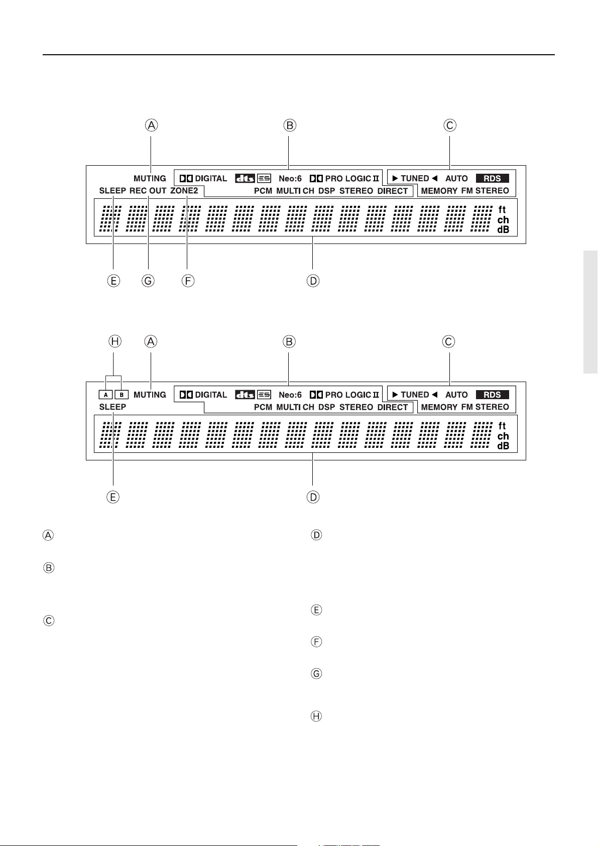
Front panel facilities
Front panel display
<TX-SR700E>
<TX-SR600E>
MUTING indicator
Flashes when the mute function is turned on.
Listening mode or digital input format indicators
One of these indicators lights to show the format of the current input
source. In addition, one of the listening mode indicators lights to
indicate the current listening mode.
Tuning indicators
TUNED indicator
Lights when a radio station is received.
AUTO indicator
Lights when receiving FM broadcasts in the stereo mode. Turns
off when placed into the monaural mode.
RDS indicator (European models only)
Lights when an RDS station is received.
MEMORY indicator
Lights when the MEMORY button is pressed to preset a radio
station.
FM STEREO indicator
Lights when an FM broadcast station is received in stereo.
Multi function display
During normal operation, shows the current input source and
volume. When the FM or AM input is selected, shows the frequency
and preset number. When the DISPLAY button is pressed, shows the
listening mode and input source format. However, does not show the
source format when the FM or AM source is selected.
SLEEP indicator
Lights when the sleep timer is turned on.
ZONE 2 indicator (TX-SR700/700E only)
Lights when using the remote zone (Zone 2).
REC OUT indicator (TX-SR700/700E only)
Lights when recording the input source from one component to
another (Rec Out).
SPEAKERS A/B indicators (TX-SR600/600E only)
Indicates which speaker system is currently in use.
11
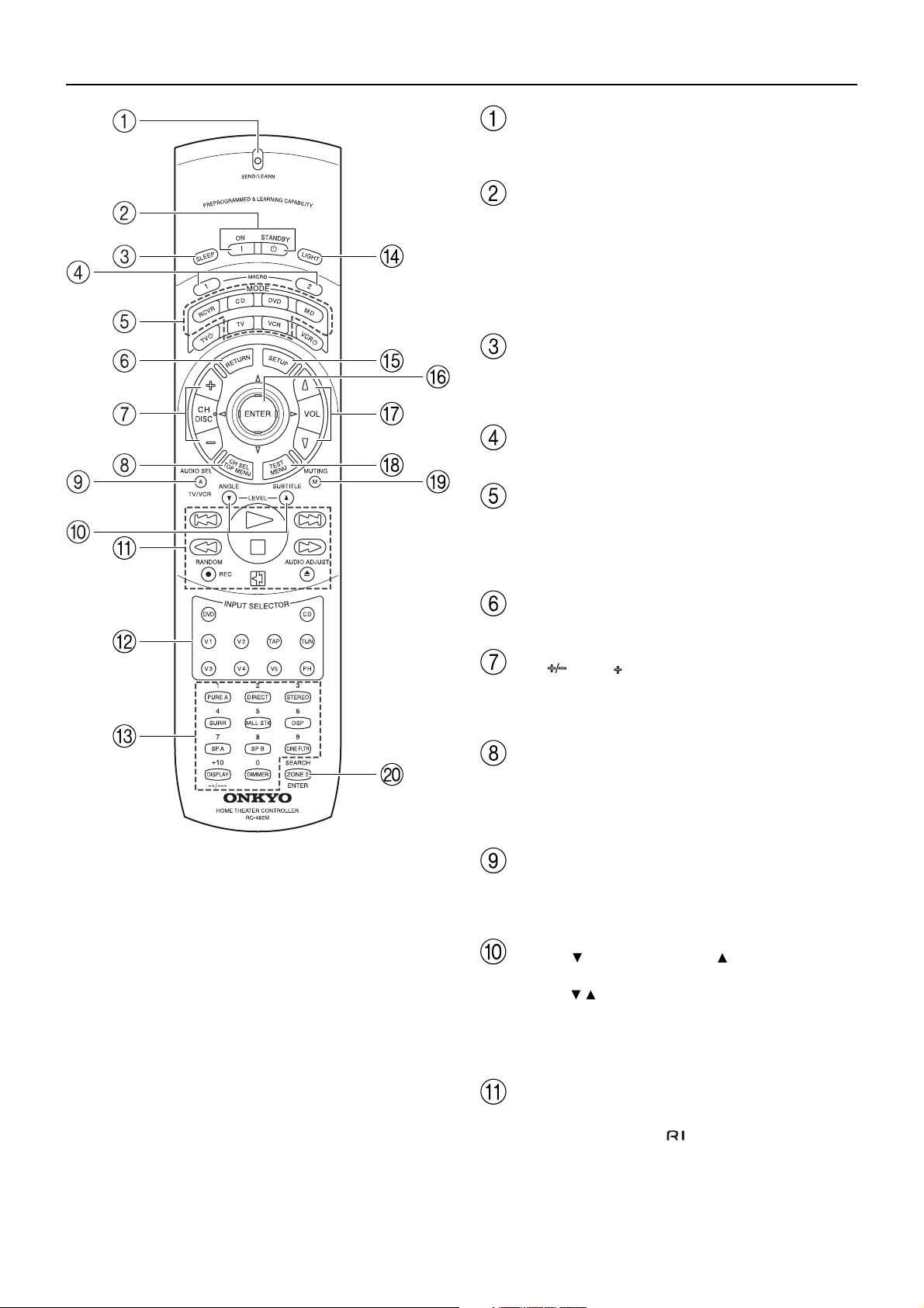
Remote controller
SEND/LEARN indicator
Lights red when signals are sent by the remote controller. It also
flashes when a button is pressed when the battery power is low.
ON/STANDBY button [33]
ON: Press to turn on the TX-SR700/700E/600/600E.
STANDBY: Press to place the TX-SR700/700E/600/600E in the
standby state.
Be aware that pressing the STANDBY button only places the TX-
SR700/700E/600/600E in standby and does not turn the power
completely off.
SLEEP button [47]
Press to set the sleep function.
The SLEEP button enables you to set the TX-SR700/700E/600/
600E to turn off automatically after a specified time period.
MACRO 1, 2 button [73]
Press to program or execute the macro function.
MODE buttons and indicators [44, 45, 64-66]
Press to select the component to be operated by the remote
controller. When a MODE button is pressed, it will light green (RC482M) or red (RC-480M) for 8 seconds. The selected MODE button
will also light whenever any other operation button is pressed.
RETURN button [36]
Press to enter the selected setting and return to the previous menu.
CH , DISC button
Press to select a preset channel for the tuner (CH). [41]
When the CD mode is selected, also press to select a disc when
operating components with disc changers (DISC). [64]
CH SEL/TOP MENU button
Press to select a speaker channel when adjusting the speaker level
(CH SEL). [39]
When the DVD mode is selected, press to display the menu screens
of the DVD player (TOP MENU). [65]
AUDIO SEL/TV/VCR button [47]
Press to select the audio input signal. The setting changes from
“Auto” to “Multich” (only if DVD is selected as the input source) to
“Analog” and back each time this button is pressed.
LEVEL /ANGLE and LEVEL /SUBTITLE buttons
Press to adjust the volume of the speaker selected using the CH SEL
button (LEVEL / ). [39]
Press the ANGLE button to select a camera angle when playing a
DVD-Video with multiple angle playback.
Press the SUBTITLE button to select a subtitle language when
playing a DVD-Video. [65]
12
CD/TAPE/DVD/MD operation buttons [63-66]
Press to operate other Onkyo components connected to the TXSR700/700E/600/600E using the
terminals.
Remote controller
INPUT SELECTOR buttons [44, 45, 53]
Press to select an input source.
Same as the input selector buttons on the front panel of the TXSR700/700E/600/600E. The input source for each button is given
here. DVD:DVD, CD:CD, V1:VIDEO1, V2:VIDEO2,
V3:VIDEO3, V4:VIDEO4, V5:VIDEO5 (not used with the TXSR700/700E/600/600E), TAP:TAPE, TUN:FM/AM, PH:PHONO
(not used with the TX-SR600/600E).
Numeric key/Listening mode, SP A, SP B, CINE
FLTR, DISPLAY, DIMMER buttons
1 to 9, +10, --/---, 0: For entering the number of a track. [64-66]
PURE A:
TX-SR600/600E: Not used with the TX-SR600/600E.
TX-SR700/700E: Press to select the Pure Audio mode. [51]
DIRECT, STEREO, SURR, ALL ST, DSP: You can select a
listening mode. [51]
Note:
During playback of a multichannel source, press the DIRECT button
to turn off the tone control and the SURR button to turn on the tone
control.
SP A, SP B:
TX-SR600/600E: Switches between speakers A and B.
TX-SR700/700E: Not used with the TX-SR700/700E.
CINE FLTR: Depending on the listening mode, you can turn the
CinemaFILTER function on or off. [52]
DISPLAY: For changing the display in the front display. [48]
DIMMER: Adjusts the display brightness.
There are three settings available: normal, dark, and very dark.
MUTING button [48]
Press to activate the mute function.
ZONE 2/SEARCH/ENTER button
When the DVD mode is selected, press to find the specific section
on a DVD where you want to start playback (SEARCH). [65]
When in the RCVR mode, press to perform operations on the remote
zone (ZONE 2) (not used with the TX-SR600/600E). [60]
When in the MD mode, press to enter the selected song (ENTER). [66]
LIGHT button (RC-482M only)
Press to turn on and off the lights in the buttons of the remote
controller.
SETUP button [36]
Press to display the Setup Menu on the TV screen and in the display.
Press again to exit the menu.
/ / / , ENTER button [36]
When in the Setup Menu, press the upper and lower arrow buttons to
select an item, press the right and left arrow buttons to select
parameter values or modes, and press the ENTER button to advance
to the next item.
VOL button [44, 45]
Press to adjust the volume.
TEST/MENU button
This button is used to set the speaker output levels. Use this button in
conjunction with the LEVEL / and CH SEL buttons to calibrate
the speakers levels without entering the Setup Menu. [39]
When the DVD mode is selected, press to display the DVD menu
(MENU). [65]
13
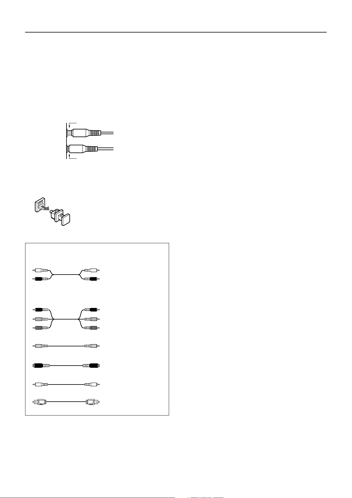
Connections
• Be sure to always refer to the instructions that came with the
component that you are connecting.
• Do not plug in the power cord until all connections have been
properly made.
• For input jacks, red connectors (marked R) are used for the
right channel, white connectors (marked L) are used for the
left channel, and yellow connectors (marked V) are used for
video connection.
• Insert all plugs and connectors securely. Improper
connections can result in noise, poor performance, or
damage to the equipment.
Improper connection
Inserted completely
• Do not bind audio/video connection cables with power cords
and speaker cables. Doing so may adversely affect the
picture and sound quality.
Optical digital terminals
The optical digital terminals are provided
with protection caps. Before you connect a
cable to a terminal, remove the cap and
keep it safely. If you disconnect the cable,
put the cap back on the terminal.
Cables are depicted in the connection diagrams as shown below.
Left (white)
Right (red)
PR
PB
Y
L
Audio connection cable
R
PR
PB
Component video
connection cable
Y
Video connection cable
S video connection cable
14
Coaxial cable
Optical cable
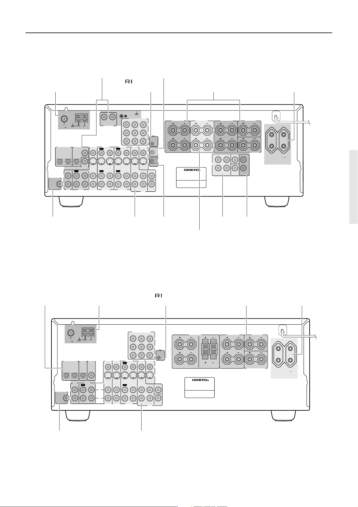
Connections
TX-SR700/700E
Connecting your audio
components [16]
ANTENNA
FM
AM
75
DIGITAL
SUBWOOFER
PRE OUT
DIGITAL INPUT
OPTICAL
2
L
R
COAXIAL
OUTPUT
OPTICAL
1
COAXIAL
DIGITAL
INPUT
IN
OUT
IN
TAPE
CD
Connecting a subwoofer [31]
CONTROL [29]
INPUT 2
L
VIDEO 1
OUT
IN
IN
OUT
IN
IN
VIDEO 1
VIDEO 3
IN
IN
VIDEO 3
OUT
OUT
R
PHONO IN
VIDEO 2
VIDEO 2
Connecting your video
components [17]
REMOTE
GND
COMPONENT VIDEO
OUTPUT
INPUT 1
DVD
MONITOR
IN
OUT
SURR
FRONT
L
R
DVD
12V TRIGGER ZONE 2
terminal [21]
FRONT
12 V
TRIGGER
OUT
IR
IN
L
R
SPEAKERS
AV RECEIVER
MODEL NO.
Y
P
B
P
R
V
S
CENTER
SUB
WOOFER
REMOTE
CONTROL
ZONE 2
IR IN [22]
When using the ZONE 2
SPEAKERS terminals [23]
Connecting speakers [31]Connecting antennas [34]
CAUTION: SPEAKER IMPEDANCE
6 OHMS MIN. /SPEAKER
2
ZONE
SPEAKERS
L
R
FRONT
L
PRE OUT
R
TX-SR700E
PRE OUT
[21]
27122974
SURROUND
SPEAKERS
SURROUND
AC OUTLETS [26]
CENTER
CENTER
SURROUND
BACK
ZONE 2
SPEAKER
SURROUND
BACK
SPEAKER
L
R
AC OUTLETS
AC 230-240 V
Hz
50
SWITCHED
TOTAL 100W MAX.
When using the ZONE 2 PRE OUT
terminals [23]
TX-SR600/600E
Connecting your audio
components [24] Connecting antennas [34]
ANTENNA
FM
75
DIGITAL
DIGITAL INPUT
OUTPUT
OPTICAL
OPTICAL
1
2
TAPE
CD
IN
OUT
L
SUBWOOFER
PRE OUT
R
Connecting a subwoofer [31]
AM
DIGITAL
INPUT
COAXIAL
VIDEO 3
VIDEO 2
IN
IN
L
R
VIDEO 3
VIDEO 2
COMPONENT VIDEO
INPUT 1
INPUT 2
VIDEO 1
DVD
OUT
ININ
OUT
IN
VIDEO 1
IN
IN
FRONT
IN
Connecting your video
components [25]
REMOTE
CONTROL [29] Connecting speakers [31] AC OUTLETS [26]
27122965
6 OHMS MIN. /SPEAKER
SURROUND
SPEAKERS
L
R
CENTER
SPEAKER
SURROUND BACK
SPEAKER
AC OUTLETS
AC 230-240 V
50
Hz
SWITCHED
TOTAL 100W MAX.
OUTPUT
MONITOR
OUT
SURR
L
R
DVD
Y
PB
PR
VIDEO
S VIDEO
CENTER
SUB
WOOFER
REMOTE
CONTROL
CAUTION: SPEAKER IMPEDANCE
FRONT
SPEAKERS
A
L
B
L
R
R
AV RECEIVER
-
MODEL NO. TX
SR600E
15
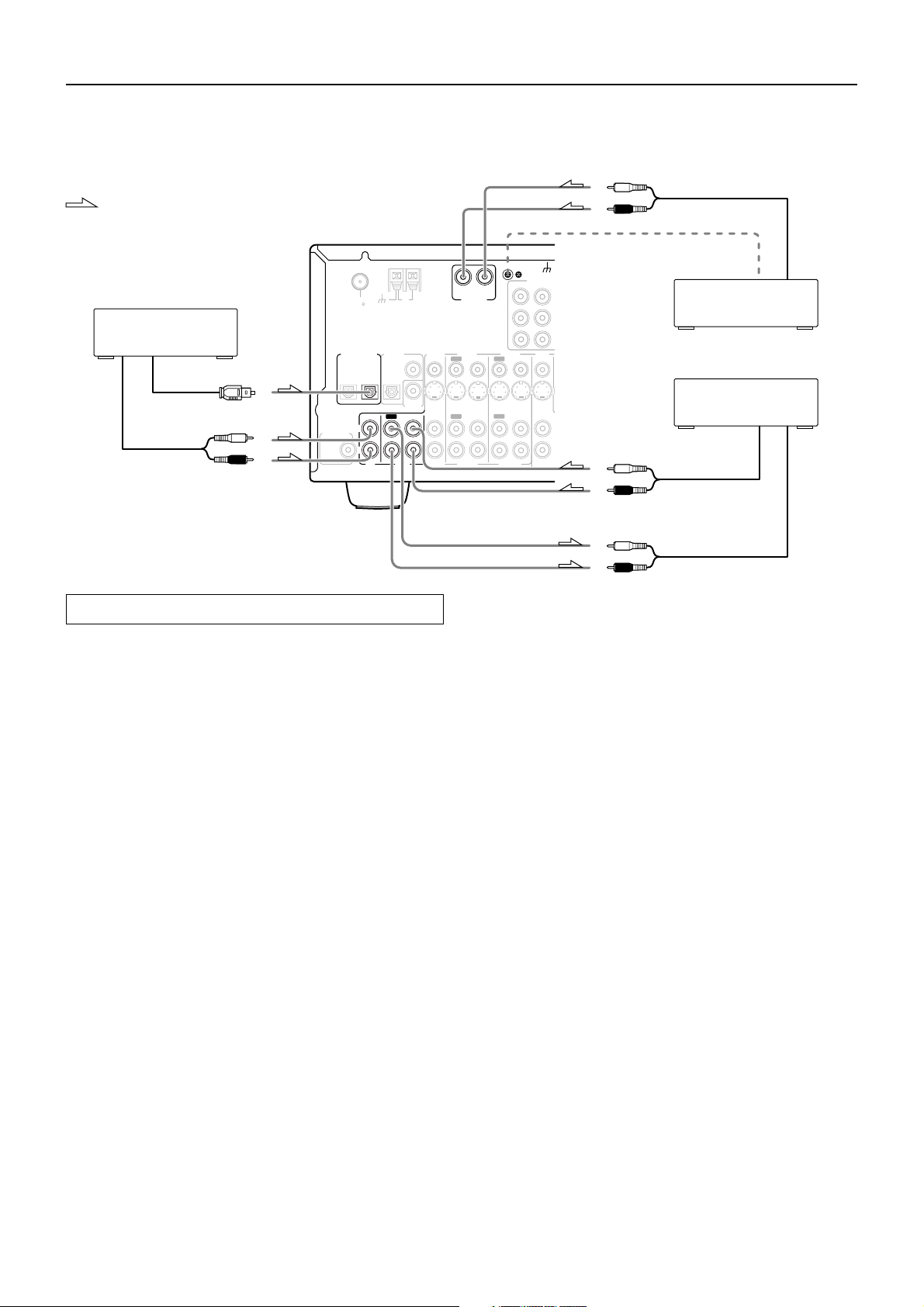
Connections (TX-SR700/700E)
L
R
Here is an explanation of typical ways to connect various components to the TX-SR700/700E. There are many ways that any one component can
be connected, and it is up to you to decide which method best fits your situation. The directions given here are only one option and should only
be thought of as such. It is best to fully understand the nature of each connector and terminal as well as those of your components and their
features to ascertain which method of connection is best.
L (white)
: Signal flow
ANTENNA
FM
AM
75
1. CD player (CD)
DIGITAL
OUTPUT
OPTICAL
OUT
TAPE
COAXIAL
COAXIAL
DIGITAL
INPUT
VIDEO 3
IN
IN
IN
VIDEO 3
Digital audio output (optical)
Analog audio output
L (white)
R (red)
SUBWOOFER
PRE OUT
DIGITAL INPUT
OPTICAL
2
L
R
1
IN
CD
Connecting your audio components
Below is an example of how you can connect your audio components
to the TX-SR700/700E. Refer to the diagram above for the following
connection examples.
AUDIO IN/OUT
These are the analog audio inputs and outputs. There are seven audio
inputs and three audio outputs on the rear panel. The audio inputs
and outputs require RCA-type connectors.
DIGITAL INPUT/OUTPUT
On the rear panel of the TX-SR700/700E, there are one coaxial
digital input, two optical digital inputs, one coaxial digital output,
and one optical digital output. To the digital inputs, connect CD
players, LD players, DVD players, or other digital source
component. To the digital outputs, connect MD recorders, CD
recorders, DAT decks, or other similar components.
• Since an analog connection must be made when using REC OUT
or ZONE 2, make sure that the connection to the input source is
not digital only, but analog as well.
• When using an optical input or output jack, always use an optical
fiber cable.
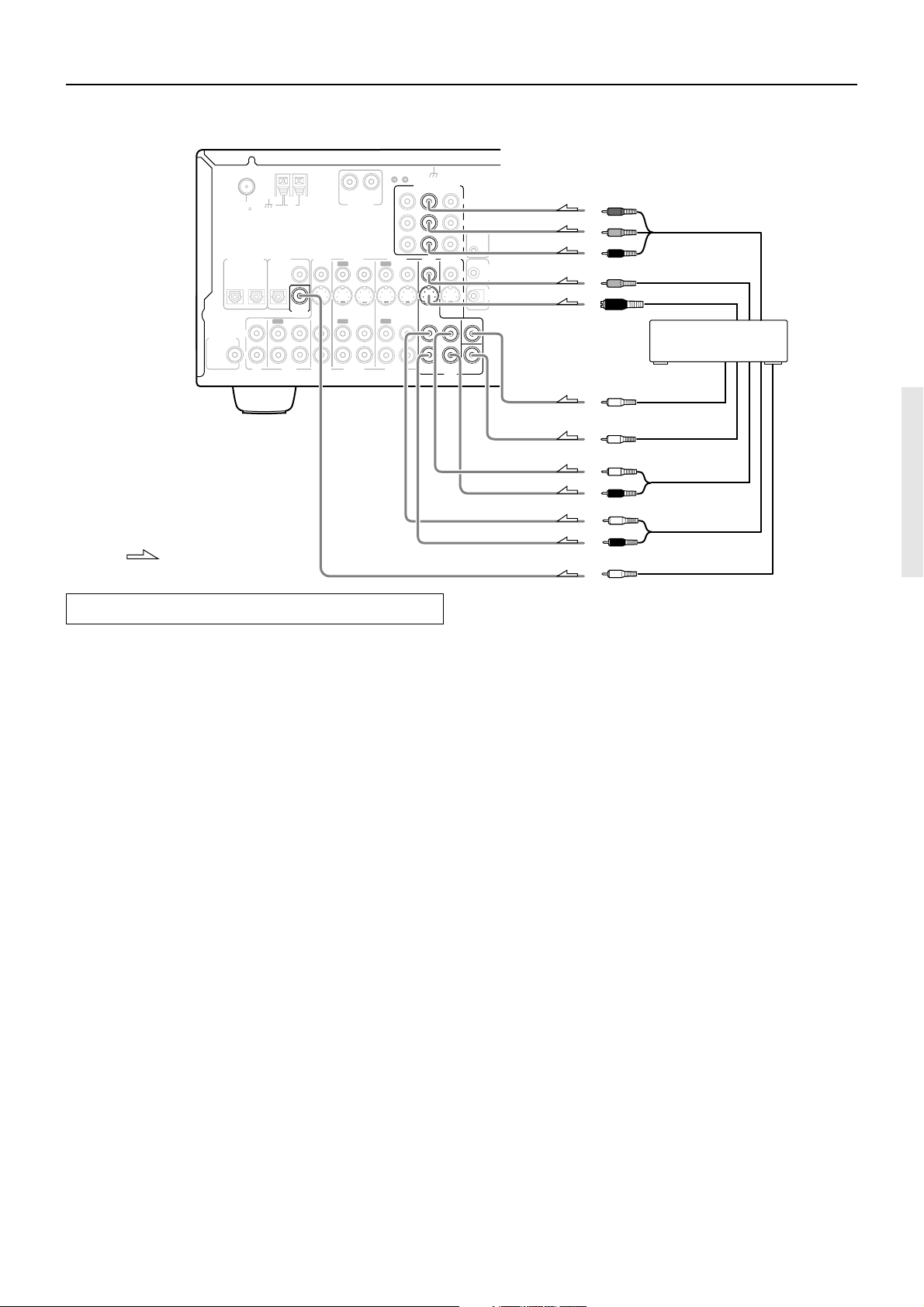
1. Connecting a compact disc player (CD)
Using an RCA audio cable, connect the output jacks of the compact
disc player to the CD audio jacks of the TX-SR700/700E. Make sure
that you properly connect the left channel to the L jack and the right
channel to the R jack.
If the compact disc player has a digital output, connect it to either the
DIGITAL INPUT COAXIAL jack or the DIGITAL INPUT
OPTICAL jack of the TX-SR700/700E depending on the type of
connector on the compact disc player.
With the initial settings of the TX-SR700/700E, the CD input
source is set for digital input at the OPTICAL 1 jack (OPT 1).
If the digital connection is made to a different jack, this must be
changed at “Input Setup” → “Digital Input” (see page 53).
Analog audio output
Ground wire (earth)
2. Turntable (PHONO)
3. Cassette tape deck, MD
recorder, DAT deck, or CD
recorder (TAPE)
Analog audio output
Analog audio input
OUT
OUT
R
PHONO IN
VIDEO 2
VIDEO 2
R (red)
GND
COMPONEN
INPUT 1
INPUT 2
L
VIDEO 1
DVD
OUT
IN
IN
IN
FRONT
OUT
IN
IN
VIDEO 1
L (white)
R (red)
L (white)
R (red)
2. Connecting a turntable (PHONO)
Using an RCA audio cable, connect the output jacks of the turntable
to the PHONO audio jacks of the TX-SR700/700E. Make sure that
you properly connect the left channel to the L jack and the right
channel to the R jack.
Note:
The TX-SR700/700E is designed for use with moving magnet
cartridges. For proper operation, connect a ground (or earth) wire to
the GND terminal. For some turntables, however, connecting the
ground wire may cause increased noise, and in such a case, a ground
wire is not necessary and should not be connected.
3. Connecting a cassette tape deck, MD recorder, DAT deck, or
CD recorder (TAPE)
Using RCA audio cables, connect the output jacks (PLAY) of the
device to the TAPE IN audio jacks of the TX-SR700/700E and
connect the input jacks (REC) of the device to the TAPE OUT audio
jacks of the TX-SR700/700E. Make sure that you properly connect
the left channels to the L jacks and the right channels to the R jacks.
If the device has a digital output, connect it to either the DIGITAL
INPUT COAXIAL jack or the DIGITAL INPUT OPTICAL jack of
the TX-SR700/700E depending on the type of connector on the
device.
With the initial settings of the TX-SR700/700E, nothing is
allocated as the digital input source for TAPE (----).
If you connect the digital audio output, be sure to make the appropriate
changes at “Input Setup” → “Digital Input” (see page 53).
If the device has a digital input, connect it to the DIGITAL OUTPUT
(OPTICAL or COAXIAL) jack of the TX-SR700/700E for digital
recording of the signal from the digital input of the TX-SR700/700E.
Note:
The output from the DIGITAL OUTPUT jack of the TX-SR700/
700E is only the digital signal input to the DIGITAL INPUT jack.
16
Connections (TX-SR700/700E)
Connecting a DVD Player with 5.1-Channel Output
DIGITAL INPUT
SUBWOOFER
PRE OUT
ANTENNA
FM
75
OPTICAL
2
L
R
VIDEO 3
IN
IN
VIDEO 3
OUT
OUT
R
PHONO IN
VIDEO 2
VIDEO 2
IN
IN
AM
DIGITAL
COAXIAL
OUTPUT
OPTICAL
1
COAXIAL
DIGITAL
INPUT
IN
OUT
IN
TAPE
CD
GND
COMPONENT VIDEO
INPUT 1
INPUT 2
L
VIDEO 1
DVD
OUT
IN
IN
FRONT
OUT
IN
VIDEO 1
: Signal flow
Connecting your video components
Below is an example of how you can connect your video components
to the TX-SR700/700E. Refer to the diagram above for the following
connection examples.
COMPONENT VIDEO INPUT/OUTPUT
For DVD players or other devices that have component video
connectors, the TX-SR700/700E has two banks of component video
input connectors (Y, P
TX-SR700/700E also has one bank of component video output
connectors for direct component video output to the matrix decoder
of a television, projector, or other display device. By sending the
pure component video signal directly, the signal forgoes the extra
processing that normally would degrade the image. The result is
vastly increased image quality, with incredibly lifelike colors and
crisp detail.
• The signal that comes in from COMPONENT VIDEO INPUT is
only sent to COMPONENT VIDEO OUTPUT. When
connecting a video player to the COMPONENT VIDEO INPUT
jacks, be sure to connect your television to the COMPONENT
VIDEO OUTPUT jacks.
VIDEO IN/OUT
These are the video inputs and outputs. On the rear panel, there are
four video inputs and two video outputs and each one includes both
composite video and S video configurations.
Connect VCRs, VTRs, LD players, DVD players, and other video
components to the video inputs. Connect VCRs, VTRs, and other
recording components to the video outputs to make video
recordings.
• When connecting a VCR or other video component, make sure
you connect its audio and video leads to the same bank (e.g.,
both to VIDEO 3).
• The VIDEO 4 inputs are located on the front panel.
B, PR) for direct component video input. The
OUTPUT
MONITOR
SURR
L
R
Y
P
B
REMOTE
CONTROL
P
R
ZONE 2
OUT
12 V
TRIGGE
V
OUT
IR
S
IN
CENTER
SUB
WOOFER
DVD
Y
P
B
Component video output
P
R
Video ouput
S video output
Analog audio output
(center)
Analog audio output
(subwoofer)
L (white)
Analog audio output
(surround L/R)
R (red)
L (white)
Analog audio output
(front L/R)
R (red)
Digital audio output
(coaxial)
4. DVD player (DVD)
The flow of the video signals is as follows:
The signal that comes in from a VIDEO IN jack is sent to both the
VIDEO OUT and S VIDEO OUT jacks. The signal that comes in
from a S VIDEO IN jack is sent to both the S VIDEO OUT and
VIDEO OUT jacks. It is not necessary to make both video and S
video connections.
Notes:
• If your video output device (e.g., television or projector) is
connected only to the MONITOR OUT VIDEO jack,
MONITOR OUT S VIDEO jack, or both, and the video signal
from the source component is input through the component
video connectors, no picture will appear. Video sources input
from the component video connectors can only be output from
the component video connectors.
• For more information about the DIGITAL INPUT/OUTPUT
jacks, see page 16.
17
Connections (TX-SR700/700E)
Connecting a DVD Player with 2-Channel (L/R) Audio Output
DIGITAL INPUT
SUBWOOFER
PRE OUT
ANTENNA
FM
75
OPTICAL
2
L
R
VIDEO 3
IN
IN
VIDEO 3
OUT
OUT
R
PHONO IN
VIDEO 2
VIDEO 2
IN
IN
AM
DIGITAL
COAXIAL
OUTPUT
OPTICAL
1
COAXIAL
DIGITAL
INPUT
IN
OUT
IN
TAPE
CD
GND
COMPONENT VIDEO
OUTPUT
INPUT 1
INPUT 2
L
VIDEO 1
DVD
OUT
OUT
VIDEO 1
MONITOR
IN
IN
SURR
FRONT
IN
L
R
DVD
: Signal flow
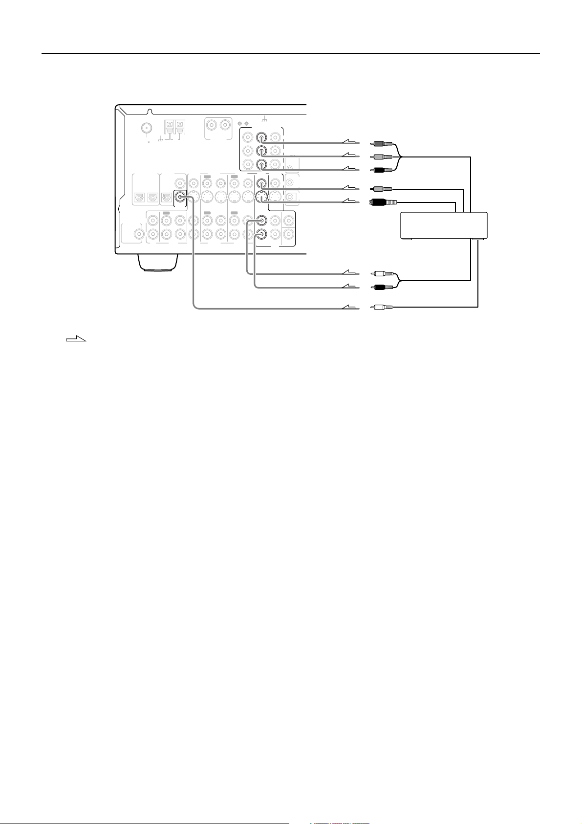
4. Connecting a DVD player (DVD)
Using an RCA video cable, connect the video output jack (composite)
of the DVD player to the DVD VIDEO IN jack of the TX-SR700/
700E. Or if the DVD player has an S video output jack, connect it to
the DVD S VIDEO IN jack with an S video cable. Or if the device has
component video outputs, connect them to the COMPONENT
VIDEO INPUT 1 or 2 jacks on the TX-SR700/700E.
With the initial settings of the TX-SR700/700E, the DVD input
source is set for the COMPONENT VIDEO INPUT 1 jacks.
If you connect the DVD player to the COMPONENT VIDEO
INPUT 2 jacks, this must be changed at “Input Setup” →
“Component Video” (see page 54).
Using an RCA audio connection cable, connect the audio output
jacks of the DVD player to the DVD FRONT L/R jacks of the TXSR700/700E. Make sure that you properly connect the left channel
to the L jack and the right channel to the R jack.
If the device has a 5.1-channel output, connect the DVD FRONT L/
R, SURR L/R, CENTER, and SUBWOOFER (5.1-channel input)
jacks of the TX-SR700/700E to the 5.1-channel output jacks of the
DVD player. Make sure that you properly connect the left channels
to the L jacks and the right channels to the R jacks.
If the device has a digital output, connect it to either the DIGITAL
INPUT COAXIAL jack or the DIGITAL INPUT OPTICAL jack of
the TX-SR700/700E depending on the type of connector on the
DVD player.
With the initial settings of the TX-SR700/700E, the DVD input
source is set for digital input at the COAXIAL jack (COAX).
If the digital connection is made at a different jack, this must be
changed at “Input Setup” → “Digital Input” (see page 53).
Note:
If the DVD player has both 5.1-channel audio outputs and 2-channel
audio outputs, and you want to connect the DVD player only using
the FRONT L/R jacks on the TX-SR700/700E, use the 2-channel
audio output jacks on the DVD player.
Y
P
B
REMOTE
CONTROL
P
R
ZONE 2
OUT
12 V
TRIGGE
V
OUT
IR
S
IN
CENTER
Y
P
B
Component video output
P
R
Video ouput
S video output
4. DVD player (DVD)
SUB
WOOFER
L (white)
R (red)
Analog audio output
Digital audio output
(coaxial)
18
Connections (TX-SR700/700E)
T
O
: Signal flow
6. Satellite tuner or television
(VIDEO 3)
Digital audio output
(optical)
Video output
S Video output
L (white)
Analog audio output
R (red)
SUBWOOFER
PRE OUT
ANTENNA
FM
75
DIGITAL INPUT
OPTICAL
2
L
R
Y
P
P
GND
COMPONENT VIDEO
OUTPUT
INPUT 1
INPUT 2
L
VIDEO 1
OUT
IN
IN
OUT
IN
IN
VIDEO 1
DVD
FRONT
Y
P
B
REMO
CONTR
P
R
MONITOR
ZONE
IN
OUT
V
S
SURR
CENTER
L
R
SUB
WOOFER
DVD
L (white)
VIDEO 3
IN
IN
VIDEO 3
OUT
OUT
R
PHONO IN
VIDEO 2
VIDEO 2
AM
DIGITAL
COAXIAL
OUTPUT
OPTICAL
1
COAXIAL
DIGITAL
INPUT
IN
OUT
IN
TAPE
CD
R (red)
Component video output
B
R
Video output
S video output
5. VCR (VIDEO 1)
Video input
S video input
Analog audio output
L (white)
R (red)
Analog audio input
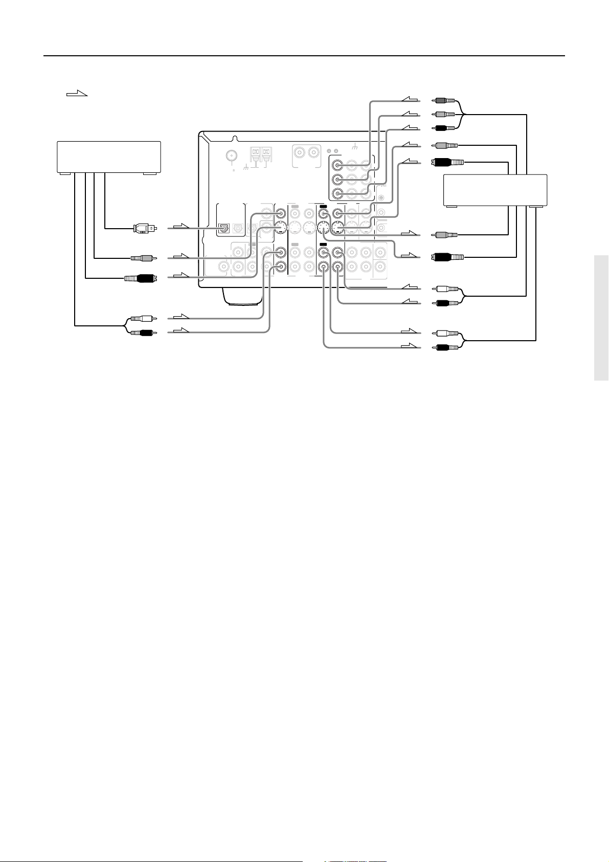
5. Connecting a video cassette recorder (VIDEO 1)
Using RCA video cables, connect the video output jack (composite)
of the video cassette recorder to the VIDEO 1 VIDEO IN jack of the
TX-SR700/700E and connect the video input jack of the video
cassette recorder to the VIDEO 1 VIDEO OUT jack of the TXSR700/700E. Or if the video cassette recorder has S video input and
output jacks, using S video cables, connect the S video output jack of
the video cassette recorder to the VIDEO 1 S VIDEO IN jack of the
TX-SR700/700E and connect the video input jack of the video
cassette recorder to the VIDEO 1 S VIDEO OUT jack of the TXSR700/700E. Or if the video cassette recorder has component video
outputs, connect them to the COMPONENT VIDEO INPUT 1 or 2
jacks on the TX-SR700/700E.
With the initial settings of the TX-SR700/700E, the VIDEO 1
input source is set for the COMPONENT VIDEO INPUT 2
jacks.
If you connect the video cassette recorder to the COMPONENT
VIDEO INPUT 1 jacks, this must be changed at “Input Setup” →
“Component Video” (see page 54).
Using RCA audio cables, connect the audio output jacks of the video
cassette recorder to the VIDEO 1 IN audio jacks of the TX-SR700/
700E and connect the audio input jacks of the video cassette recorder
to the VIDEO 1 OUT audio jacks of the TX-SR700/700E. Make sure
that you properly connect the left channels to the L jacks and the
right channels to the R jacks.
With the initial settings of the TX-SR700/700E, nothing is
allocated as the digital input source for VIDEO 1 (----).
If you connect the digital audio output, be sure to make the appropriate
changes at “Input Setup” → “Digital Input” (see page 53).
6. Connecting a satellite tuner, television, or settop box
(VIDEO 3)
Using an RCA video cable, connect the video output jack
(composite) of the device to the VIDEO 3 VIDEO IN jack of the TXSR700/700E. Or if the device has an S video output jack, connect it
to the VIDEO 3 S VIDEO IN jack of the TX-SR700/700E using an S
video cable. Or if the device has component video outputs, connect
them to the COMPONENT VIDEO INPUT 1 or 2 jacks on the TXSR700/700E.
With the initial settings of the TX-SR700/700E, the VIDEO 3
input source is set for the COMPONENT VIDEO INPUT 2
jacks.
If you connect the device to the COMPONENT VIDEO INPUT 1
jacks, this must be changed at “Input Setup” → “Component Video”
(see page 54).
Using an RCA audio cable, connect the audio output jack of the
device to the VIDEO 3 IN audio jacks of the TX-SR700/700E. Make
sure that you properly connect the left channel to the L jack and the
right channel to the R jack.
If the device has a digital output, connect it to either the DIGITAL
INPUT COAXIAL jack or the DIGITAL INPUT OPTICAL jack of
the TX-SR700/700E depending on the type of connector on the
device.
With the initial settings of the TX-SR700/700E, the VIDEO 3 input
source is set for digital input at the OPTICAL 2 jack (OPT 2).
If the digital connection is made at a different jack, this must be
changed at “Input Setup” → “Digital Input” (see page 53).
19
Connections (TX-SR700/700E)
T
O
8. TV monitor or projector
(MONITOR OUT)
Component video
input
S Video input
Video input
P
R
P
B
Y
7. DVD recorder, other digital
video recording device
(VIDEO 2)
R (red)
L (white)
R (red)
L (white)
Video input
S Video input
Video output
S Video output
Analog audio input
Analog audio output
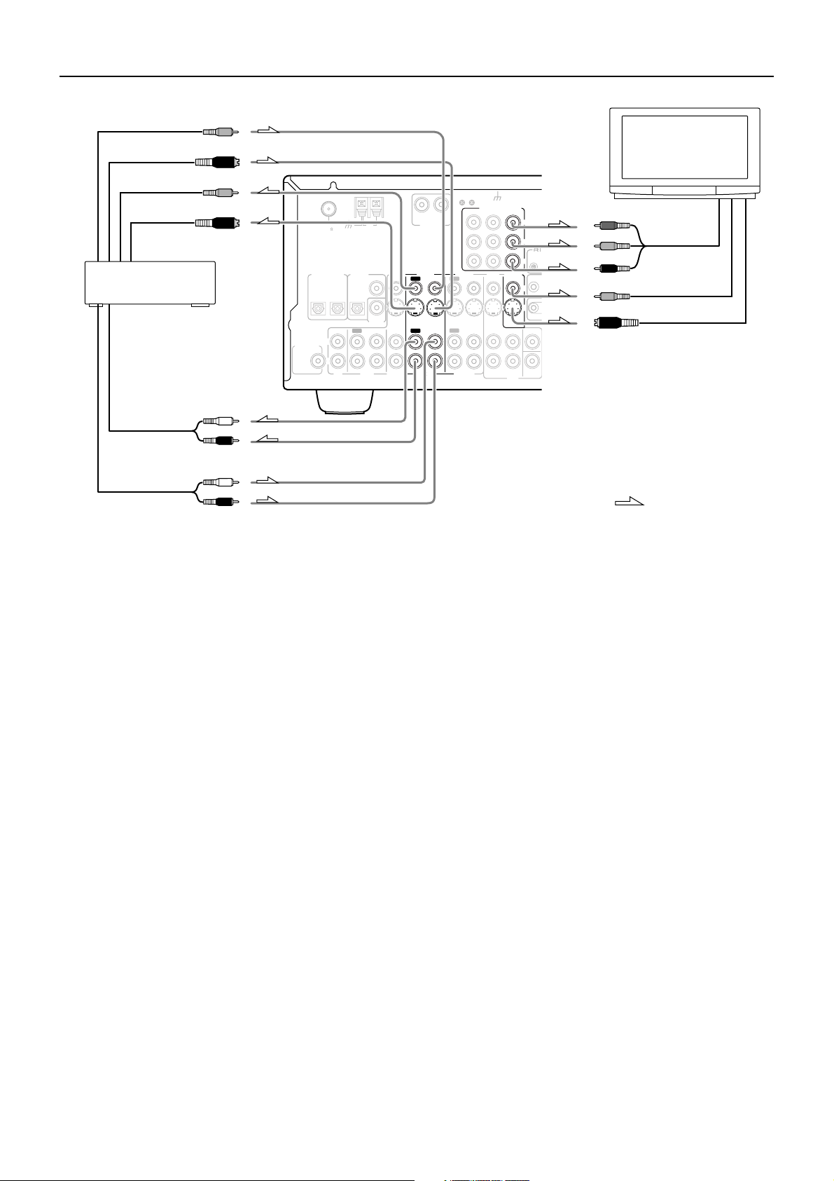
7. Connecting a DVD recorder or other digital video recording
device (VIDEO 2)
Using RCA video cables, connect the video output jack (composite)
of the device to the VIDEO 2 VIDEO IN jack of the TX-SR700/
700E and connect the video input jack of the device to the VIDEO 2
VIDEO OUT jack of the TX-SR700/700E. Or if the device has S
video input and output jacks, using S video cables, connect the S
video output jack of the device to the VIDEO 2 S VIDEO IN jack of
the TX-SR700/700E and connect the video input jack of the device
to the VIDEO 2 S VIDEO OUT jack of the TX-SR700/700E. Or if
the device has component video outputs, connect them to the
COMPONENT VIDEO INPUT 1 or 2 jacks on the TX-SR700/
700E.
With the initial settings of the TX-SR700/700E, the VIDEO 2
input source is set for the COMPONENT VIDEO INPUT 2
jacks.
If you connect the device to the COMPONENT VIDEO INPUT 1
jacks, this must be changed at “Input Setup” → “Component Video”
(see page 54).
Using RCA audio cables, connect the audio output jacks of the
device to the VIDEO 2 IN audio jacks of the TX-SR700/700E and
connect the audio input jacks of the device to the VIDEO 2 OUT
audio jacks of the TX-SR700/700E. Make sure that you properly
connect the left channels to the L jacks and the right channels to the
R jacks.
If the device has a digital output, connect it to either the DIGITAL
INPUT COAXIAL jack or the DIGITAL INPUT OPTICAL jack of
the TX-SR700/700E depending on the type of connector on the
device.
With the initial settings of the TX-SR700/700E, nothing is
allocated as the digital input source for VIDEO 2 (----).
If you connect the digital audio output, be sure to make the appropriate
changes at “Input Setup” → “Digital Input” (see page 53).
If the device has a digital input, connect it to the DIGITAL OUTPUT
(OPTICAL or COAXIAL) jack of the TX-SR700/700E for digital
recording of the signal from the digital input of the TX-SR700/
700E.
20
DIGITAL INPUT
SUBWOOFER
PRE OUT
ANTENNA
FM
75
OPTICAL
2
L
R
GND
COMPONENT VIDEO
OUTPUT
INPUT 1
INPUT 2
L
VIDEO 1
OUT
IN
IN
OUT
IN
IN
VIDEO 1
DVD
FRONT
Y
P
B
REMO
CONTR
P
R
MONITOR
ZONE
IN
OUT
V
S
SURR
CENTER
L
R
SUB
WOOFER
DVD
VIDEO 3
IN
IN
VIDEO 3
OUT
OUT
VIDEO 2
VIDEO 2
R
PHONO IN
AM
DIGITAL
COAXIAL
OUTPUT
OPTICAL
1
COAXIAL
DIGITAL
INPUT
IN
OUT
IN
TAPE
CD
: Signal flow
Note:
The output from the DIGITAL OUTPUT jack of the TX-SR700/
700E is only the digital signal input to the DIGITAL INPUT jack.
8. Connecting a television monitor or projector (MONITOR
OUT)
The TX-SR700/700E is equipped with a simple Y/C separate circuit
and simple Y/C mixed circuit. Since both the signal from the S
VIDEO and VIDEO inputs are output to the MONITOR OUT S
VIDEO output, if the television or projector is equipped with an S
video input, it is unnecessary to connect the video connectors. If it is
equipped with only a video input, connect it to the MONITOR OUT
VIDEO output.
Using an RCA video cable, connect the video input jack (composite)
of the device to the MONITOR OUT VIDEO jack of the TX-SR700/
700E. Or if the device has an S video input jack, connect it to the
MONITOR OUT S VIDEO jack of the TX-SR700/700E using an S
video cable. Or if the device has component video inputs, connect
them to the bank of COMPONENT VIDEO OUTPUT jacks on the
TX-SR700/700E.
Note:
Note that the Setup Menu will only be displayed on the monitor
connected to MONITOR OUT and not those connected to the
COMPONENT VIDEO OUTPUT jacks.
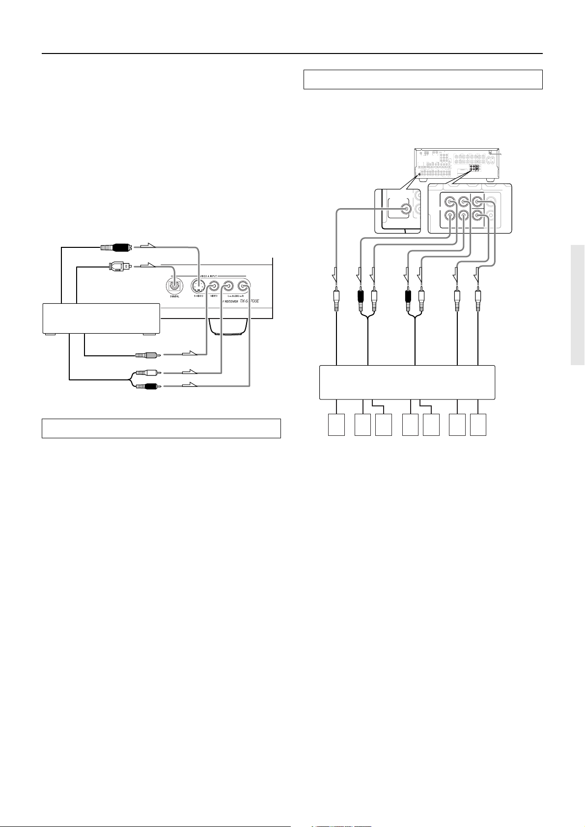
Connections (TX-SR700/700E)
L
CD
SUBWOOFER
PRE OUT
R
FRONT
SURROUND
CENTER
ZONE 2
SURROUND
BACK
R
L
R
L
PRE OUT
SURROU
BACK
SPEAKE
9. Connecting video camera, etc. (VIDEO 4 INPUT)
Using an RCA video cable, connect the video output jack
(composite) of the device to the VIDEO 4 VIDEO jack of the TXSR700/700E. Or if the device has an S video output jack, connect it
to the VIDEO 4 S VIDEO jack of the TX-SR700/700E using an S
video cable.
Using an RCA audio cable, connect the audio output jack of the
device to the VIDEO 4 AUDIO jacks of the TX-SR700/700E. Make
sure that you properly connect the left channel to the L jack and the
right channel to the R jack.
If the device has an optical digital output, connect it to the VIDEO 4
DIGITAL jack of the TX-SR700/700E.
The VIDEO 4 digital input is fixed to the OPTICAL input on the
front panel.
S Video output
Digital output
(optical)
9. Video camera/Video game
(VIDEO 4 INPUT)
Video output
Left (white)
PRE OUT
These jacks are for connecting an auxiliary power amplifier.
You can use an auxiliary power amplifiers to listen at louder
volumes than you can with the TX-SR700/700E alone. When using a
power amplifier, connect each speaker to the power amplifier.
27122974
ANTENNA
R
FM
AM
PHONO IN
75
DIGITAL
VIDEO 2
VIDEO 3
DIGITAL INPUT
COAXIAL
OUT
IN
OUTPUT
OPTICAL
OPTICAL
1
2
COAXIAL
DIGITAL
INPUT
IN
OUT
IN
OUT
IN
L
SUBWOOFER
PRE OUT
R
TAPE
CD
VIDEO 3
VIDEO 2
R (red)
L (white)
R (red)
L (white)
Subwoofer
Front
Surround
CAUTION: SPEAKER IMPEDANCE
GND
6 OHMS MIN. /SPEAKER
COMPONENT VIDEO
OUTPUT
INPUT 1INPUT 2
L
Y
P
B
REMOTE
CONTROL
P
R
VIDEO 1
DVD
MONITOR
ZONE 2
OUT
IN
IN
IN
OUT
V
S
SURR
CENTER
FRONT
OUT
IN
IN
L
R
SUB
VIDEO 1
WOOFER
DVD
CENTER
SURROUND
ZONE
2
FRONT
SPEAKERS
SPEAKER
SPEAKERS
SPEAKERS
L
R
12 V
TRIGGER
OUT
IR
IN
MODEL NO.
Surround back
AC OUTLETS
L
R
SURROUND
BACK
ZONE 2
SURROUND
CENTER
FRONT
SPEAKER
AC 230-240 V
50
Hz
L
L
SWITCHED
TOTAL 100W MAX.
PRE OUT
R
R
AV RECEIVER
SURROUND
BACK
TX-SR700E
Center
Analog output
Right (red)
12V TRIGGER ZONE 2 terminal
When the TX-SR700/700E is in the ZONE 2 mode, this terminal
outputs at 12 V/100 mA.
Power amplifier
1. Subwoofer
2. Front right speaker
3. Front left speaker
4. Surround right speaker
7654321
5. Surround left speaker
6. Surround back speaker
7. Center speaker
21
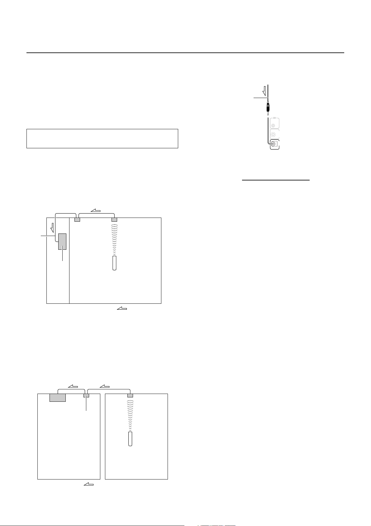
Operating components not reached by the remote
controller signals (IR IN) (TX-SR700/700E only)
In order to use the remote controller to control the TX-SR700/
700E from a remote location, you will need to prepare a multiroom kit (sold separately) such as one of those given below:
• Onkyo’s Multi-Room System kit (IR Remote Controller
Extension System)
• Multiroom A/V distribution and control system such as those
from Niles
®
and Xantech
®
If the remote controller signal does not reach the
TX-SR700/700E remote sensor
If the TX-SR700/700E is located inside a cabinet or other enclosure
where the infrared rays from the remote controller cannot enter, then
operation with the remote controller will not be possible. In such a
case, it will be necessary to install a remote sensor at a location
outside of the cabinet where the infrared rays from the controller can
reach.
With this connection, select “Main” at “Preference” → “IR IN
Position” (see page 56).
IR Receiver
IR IN
Connecting
block
Make the connections as shown below. Do not plug in any
equipment to the power outlet until all the connections are complete.
From connecting block
Mini plug cable
REMOTE
CONTROL
ZONE 2
12 V
TRIGGER
OUT
IR
IN
TX-SR700/700E
TX-SR700
/700E
In the
cabinet
Remote Controller
: Signal flow
The IR IN input allows you to control the TX-SR700/700E from the
remote zone (Zone 2) with the remote controller even though the
remote zone may be on the other side of the building from the main
zone. The diagram below shows how to make the proper connections
for the remote zone.
With this connection, select “Zone 2” at “Preference” → “IR IN
Position” (see page 56).
To IR IN
IR Receiver
TX-SR700/700E
Connecting
block
22
Main room
Remote controller
Zone 2 room
: Signal flow
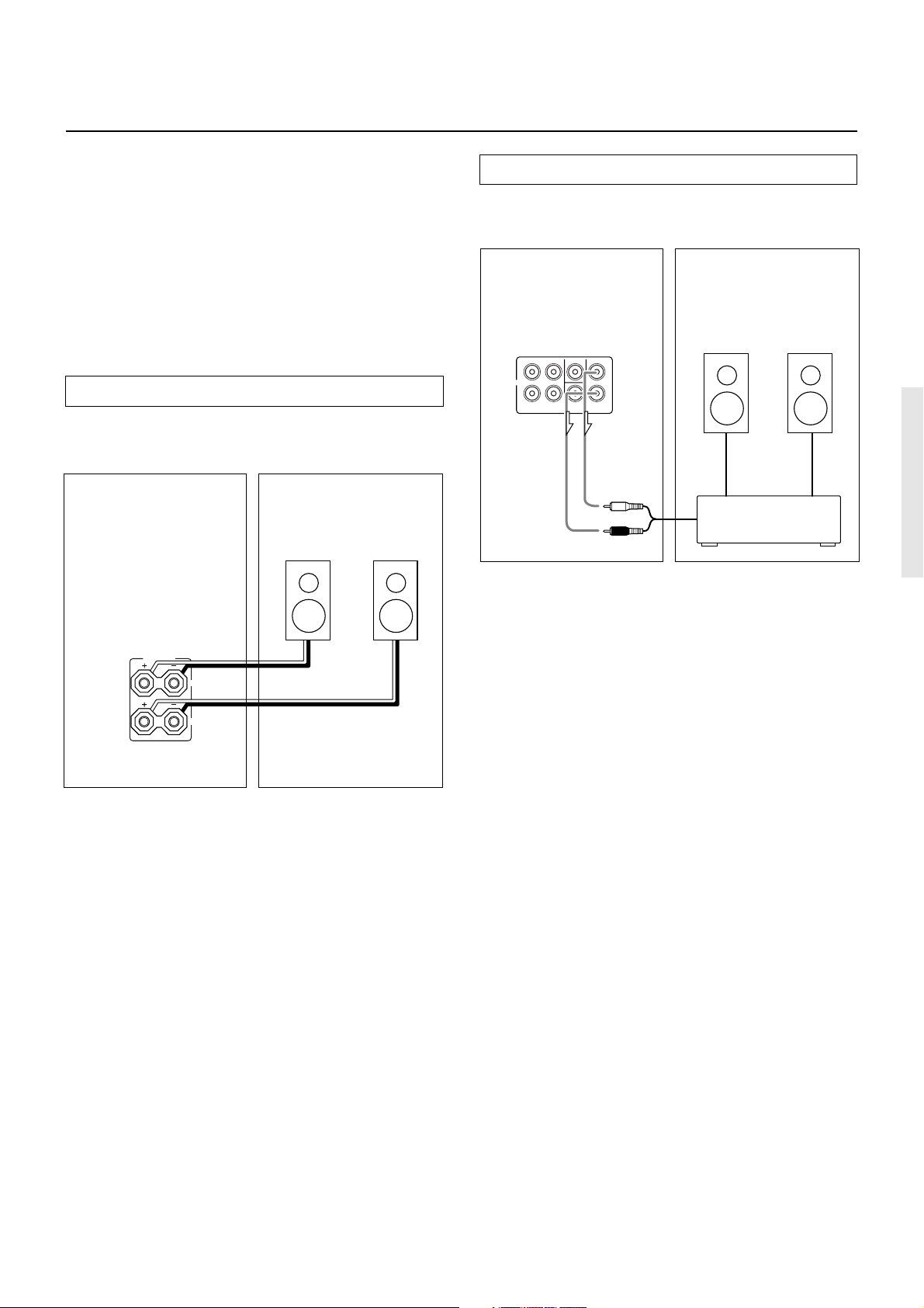
Connecting the remote zone (Zone 2) speakers
(TX-SR700/700E only)
The TX-SR700/700E allows you to listen to two separate input
sources at the same time. This allows you to, for example, place
speakers in two different rooms so that two or more people can enjoy
two different kinds of music at the same time. The room where the
TX-SR700/700E is actually located is referred to as the main room
while the separate room is referred to as the remote zone (Zone 2). In
addition, the IR IN terminal of the TX-SR700/700E allows you to
control the TX-SR700/700E from the remote zone (Zone 2) with the
remote controller even though the remote zone is physically
separated. The diagram below shows how to make the proper
connections for the remote zone.
When using the ZONE 2 SPEAKERS terminals
If you are using a 5.1-channel speaker system in the main room, you
can connect the speakers for the remote zone (Zone 2) to the open
ZONE 2 SPEAKERS terminals.
Remote Zone (Zone 2)Main Room
Zone 2
Left
speaker
Zone 2
Right
speaker
When using the ZONE 2 PRE OUT terminals
If you are using a 5.1-channel speaker system in the main room, you
can connect the amplifier for the remote zone (Zone 2) to the open
ZONE 2 PRE OUT terminals and connect the remote zone speakers.
Remote Zone (Zone 2)Main Room
Zone 2
Right
speaker
TX-SR700/700E
SURROUND
FRONT
L
PRE OUT
R
SURROUND
ZONE 2
CENTER
BACK
Left (white)
Right (red)
Zone 2
Left
speaker
L
R
Power amplifier
ZONE 2
SPEAKERS
L
R
TX-SR700/700E
Note:
It is important to be aware of the speaker impedance (see page 31).
23
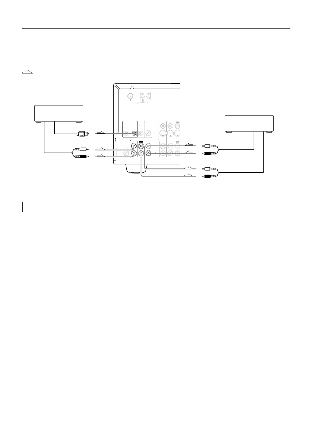
Connections (TX-SR600/600E)
D
D
Here is an explanation of typical ways to connect various components to the TX-SR600/600E. There are many ways that any one component can
be connected, and it is up to you to decide which method best fits your situation. The directions given here are only one option and should only
be thought of as such. It is best to fully understand the nature of each connector and terminal as well as those of your components and their
features to ascertain which method of connection is best.
: Signal flow
ANTENNA
FM
AM
75
1. CD player (CD)
2. Cassette tape deck, MD
recorder, DAT deck, or CD
recorder (TAPE)
Analog audio output
Digital audio output (optical)
Analog audio output
L (white)
R (red)
SUBWOOFER
PRE OUT
DIGITAL INPUT
OPTICAL
2
L
R
VIDEO 3
VIDEO 2
DIGITAL
DIGITAL
OUTPUT
INPUT
COAXIAL
OPTICAL
1
TAPE
CD
IN
OUT
IN
IN
L
R
VIDEO 3
ININ
IN
VIDEO 2
VI
OUT
OUT
VI
L (white)
R (red)
L (white)
Connecting your audio components
Below is an example of how you can connect your audio components
to the TX-SR600/600E. Refer to the diagram above for the following
connection examples.
AUDIO IN/OUT
These are the analog audio inputs and outputs. There are six audio
inputs and two audio outputs on the rear panel. The audio inputs and
outputs require RCA-type connectors.
DIGITAL INPUT/OUTPUT
On the rear panel of the TX-SR600/600E, there are one coaxial
digital input, two optical digital inputs, and one optical digital
output. To the digital inputs, connect CD players, LD players, DVD
players, or other digital source component. To the digital output,
connect an MD recorder, CD recorder, DAT deck, or other similar
component.
• Since an analog connection must be made when using REC
OUT, make sure that the connection to the input source is not
digital only, but analog as well.
• When using an optical input or output jack, always use an optical
fiber cable.
R (red)
Analog audio input
2. Connecting a cassette tape deck, MD recorder, DAT deck, or
CD recorder (TAPE)
Using RCA audio cables, connect the output jacks (PLAY) of the
device to the TAPE IN audio jacks of the TX-SR600/600E and
connect the input jacks (REC) of the device to the TAPE OUT audio
jacks of the TX-SR600/600E. Make sure that you properly connect
the left channels to the L jacks and the right channels to the R jacks.
If the device has a digital output, connect it to either the DIGITAL
INPUT COAXIAL jack or the DIGITAL INPUT OPTICAL jack of
the TX-SR600/600E depending on the type of connector on the
device.
With the initial settings of the TX-SR600/600E, nothing is
allocated as the digital input source for TAPE (----).
If you connect the digital audio output, be sure to make the appropriate
changes at “Input Setup” → “Digital Input” (see page 53).
If the device has a digital input, connect it to the DIGITAL OUTPUT
OPTICAL jack of the TX-SR600/600E for digital recording of the
signal from the digital input of the TX-SR600/600E.
Note:
The output from the DIGITAL OUTPUT jack of the TX-SR600/
600E is only the digital signal input to the DIGITAL INPUT jack.
1. Connecting a compact disc player (CD)
Using an RCA audio cable, connect the output jacks of the compact
disc player to the CD audio jacks of the TX-SR600/600E. Make sure
that you properly connect the left channel to the L jack and the right
channel to the R jack.
If the compact disc player has a digital output, connect it to either the
DIGITAL INPUT COAXIAL jack or the DIGITAL INPUT
OPTICAL jack of the TX-SR600/600E depending on the type of
connector on the compact disc player.
With the initial settings of the TX-SR600/600E, the CD input
source is set for digital input at the OPTICAL 1 jack (OPT 1).
If the digital connection is made to a different jack, this must be
changed at “Input Setup” → “Digital Input” (see page 53).
24
 Loading...