


 Loading...
Network Stereo Receiver
TX-8050
Instruction Manual
Thank you for purchasing an Onkyo Network Stereo Receiver. Please read this manual thoroughly before making connections and plugging in the unit.
Following the instructions in this manual will enable you to obtain optimum performance and listening enjoyment from your new Stereo Receiver.
Please retain this manual for future reference.
Contents
..................................Introduction |
En-2 |
|
|
..............................Connections |
En-10 |
|
|
Enjoying Audio Sources...... En-18
Appendix |
|
Troubleshooting..................... |
En-51 |
Specifications ......................... |
En-54 |
|
|
En
WARNING:
TO REDUCE THE RISK OF FIRE OR ELECTRIC SHOCK, DO NOT EXPOSE THIS APPARATUS TO RAIN OR MOISTURE.
CAUTION:
TO REDUCE THE RISK OF ELECTRIC SHOCK, DO NOT REMOVE COVER (OR BACK). NO USER-SERVICEABLE PARTS INSIDE. REFER SERVICING TO QUALIFIED SERVICE PERSONNEL.
WARNING |
|
AVIS |
RISK OF ELECTRIC SHOCK |
|
RISQUE DE CHOC ELECTRIQUE |
DO NOT OPEN |
|
NE PAS OUVRIR |
The lightning flash with arrowhead symbol, within an equilateral triangle, is intended to alert the user to the presence of uninsulated “dangerous voltage” within the product’s enclosure that may be of sufficient
magnitude to constitute a risk of electric shock to persons.
The exclamation point within an equilateral triangle is intended to alert the user to the presence of important operating and maintenance (servicing) instructions in the literature accompanying the appliance.
Important Safety Instructions
1.Read these instructions.
2.Keep these instructions.
3.Heed all warnings.
4.Follow all instructions.
5.Do not use this apparatus near water.
6.Clean only with dry cloth.
7.Do not block any ventilation openings. Install in accordance with the manufacturer’s instructions.
8.Do not install near any heat sources such as radiators, heat registers, stoves, or other apparatus (including amplifiers) that produce heat.
9.Do not defeat the safety purpose of the polarized or grounding-type plug. A polarized plug has two blades with one wider than the other. A grounding type plug has two blades and a third grounding prong. The wide blade or the third prong are provided for your safety. If the provided plug does not fit into your outlet, consult an electrician for replacement of the obsolete outlet.
10.Protect the power cord from being walked on or pinched particularly at plugs, convenience receptacles, and the point where they exit from the apparatus.
11.Only use attachments/accessories specified by the manufacturer.
12.Use only with the cart, stand, tripod, bracket, or table specified by the manufacturer, or sold with the apparatus. When a cart is used, use caution when moving the cart/ apparatus combination to avoid injury from tip-over.
PORTABLE CART WARNING
S3125A
13.Unplug this apparatus during lightning storms or when unused for long periods of time.
14.Refer all servicing to qualified service personnel. Servicing is required when the apparatus has been damaged in any way, such as power-supply cord or plug is damaged, liquid has been spilled or objects have fallen into the apparatus, the apparatus has been exposed to rain or moisture, does not operate normally, or has been dropped.
15.Damage Requiring Service
Unplug the apparatus from the wall outlet and refer servicing to qualified service personnel under the following conditions:
A.When the power-supply cord or plug is damaged,
B.If liquid has been spilled, or objects have fallen into the apparatus,
C.If the apparatus has been exposed to rain or water,
D.If the apparatus does not operate normally by following the operating instructions. Adjust only those controls that are covered by the operating instructions as an improper adjustment of other controls may result in damage and will often require extensive work by a qualified technician to restore the apparatus to its normal operation,
E.If the apparatus has been dropped or damaged in any way, and
F.When the apparatus exhibits a distinct change in performance this indicates a need for service.
16.Object and Liquid Entry
Never push objects of any kind into the apparatus through openings as they may touch dangerous voltage points or short-out parts that could result in a fire or electric shock.
The apparatus shall not be exposed to dripping or splashing and no objects filled with liquids, such as vases shall be placed on the apparatus.
Don’t put candles or other burning objects on top of this unit.
17.Batteries
Always consider the environmental issues and follow local regulations when disposing of batteries.
18.If you install the apparatus in a built-in installation, such as a bookcase or rack, ensure that there is adequate ventilation.
Leave 20 cm (8") of free space at the top and sides and 10 cm (4") at the rear. The rear edge of the shelf or board above the apparatus shall be set 10 cm (4") away from the rear panel or wall, creating a fluelike gap for warm air to escape.
En-2

Precautions
1.Recording Copyright—Unless it’s for personal use only, recording copyrighted material is illegal without the permission of the copyright holder.
2.AC Fuse—The AC fuse inside the unit is not userserviceable. If you cannot turn on the unit, contact your Onkyo dealer.
3.Care—Occasionally you should dust the unit all over with a soft cloth. For stubborn stains, use a soft cloth dampened with a weak solution of mild detergent and water. Dry the unit immediately afterwards with a clean cloth. Don’t use abrasive cloths, thinners, alcohol, or other chemical solvents, because they may damage the finish or remove the panel lettering.
4.Power WARNING
BEFORE PLUGGING IN THE UNIT FOR THE FIRST TIME, READ THE FOLLOWING SECTION CAREFULLY.
AC outlet voltages vary from country to country. Make sure that the voltage in your area meets the voltage requirements printed on the unit’s rear panel (e.g., AC 230 V, 50 Hz or AC 120 V, 60 Hz).
The power cord plug is used to disconnect this unit from the AC power source. Make sure that the plug is readily operable (easily accessible) at all times.
Pressing ON/STANDBY to select Standby mode does not fully disconnect from the mains. If you do not intend to use the unit for an extended period, remove the power cord from the AC outlet.
5.Preventing Hearing Loss Caution
Excessive sound pressure from earphones and headphones can cause hearing loss.
6.Batteries and Heat Exposure Warning
Batteries (battery pack or batteries installed) shall not be exposed to excessive heat as sunshine, fire or the like.
7.Never Touch this Unit with Wet Hands—Never handle this unit or its power cord while your hands are wet or damp. If water or any other liquid gets inside this unit, have it checked by your Onkyo dealer.
8.Handling Notes
•If you need to transport this unit, use the original packaging to pack it how it was when you originally bought it.
•Do not leave rubber or plastic items on this unit for a long time, because they may leave marks on the case.
•This unit’s top and rear panels may get warm after prolonged use. This is normal.
•If you do not use this unit for a long time, it may not work properly the next time you turn it on, so be sure to use it occasionally.
For U.S. models
FCC Information for User
CAUTION:
The user changes or modifications not expressly approved by the party responsible for compliance could void the user’s authority to operate the equipment.
NOTE:
This equipment has been tested and found to comply with the limits for a Class B digital device, pursuant to Part 15 of the FCC Rules. These limits are designed to provide reasonable protection against harmful interference in a residential installation.
This equipment generates, uses and can radiate radio frequency energy and, if not installed and used in accordance with the instructions, may cause harmful interference to radio communications. However, there is no guarantee that interference will not occur in a particular installation. If this equipment does cause harmful interference to radio or television reception, which can be determined by turning the equipment off and on, the user is encouraged to try to correct the interference by one or more of the following measures:
•Reorient or relocate the receiving antenna.
•Increase the separation between the equipment and receiver.
•Connect the equipment into an outlet on a circuit different from that to which the receiver is connected.
•Consult the dealer or an experienced radio/TV technician for help.
For Canadian Models
NOTE: THIS CLASS B DIGITAL APPARATUS COMPLIES WITH CANADIAN ICES-003.
Modèle pour les Canadien
REMARQUE: CET APPAREIL NUMÉRIQUE DE LA CLASSE B EST CONFORME À LA NORME NMB-003 DU CANADA.
En-3

Precautions—Continued
For British models
Replacement and mounting of an AC plug on the power supply cord of this unit should be performed only by qualified service personnel.
IMPORTANT
The wires in the mains lead are coloured in accordance with the following code:
Blue: Neutral
Brown: Live
As the colours of the wires in the mains lead of this apparatus may not correspond with the coloured markings identifying the terminals in your plug, proceed as follows:
The wire which is coloured blue must be connected to the terminal which is marked with the letter N or coloured black.
The wire which is coloured brown must be connected to the terminal which is marked with the letter L or coloured red.
IMPORTANT
The plug is fitted with an appropriate fuse. If the fuse needs to be replaced, the replacement fuse must approved by ASTA or BSI to BS1362 and have the same ampere rating as that indicated on the plug. Check for the ASTA mark or the BSI mark on the body of the fuse.
If the power cord’s plug is not suitable for your socket outlets, cut it off and fit a suitable plug. Fit a suitable fuse in the plug.
For European Models
Declaration of Conformity
We, ONKYO EUROPE ELECTRONICS GmbH LIEGNITZERSTRASSE 6, 82194 GROEBENZELL, GERMANY
declare in own responsibility, that the ONKYO product described in this instruction manual is in compliance with the corresponding technical standards such as EN60065, EN55013, EN55020 and EN61000-3-2, -3-3.
GROEBENZELL, GERMANY
K. MIYAGI
ONKYO EUROPE ELECTRONICS GmbH
Features
Clean Design Aluminum Front Panel
Network Capability
•Internet Radio
•DLNA (Digital Living Network Alliance)
iPod/iPhone*1 Digital Direct Connection via USB
USB Mass-strage Class Device Compatible USB
Music Optimizer*2 for Compressed Digital Music Files
WRAT (Wide Range Amplifier Technology)
Discrete Amplifier with Massive Transformer
Zone 2 Capability
Gold Plated Terminals
130 Watts/channel @ 6 Ω (IEC)
100 Watts/channel @ 6 Ω (FTC)
AM/FM 40 Presets
RDS (PS/PTY/RT/TP) (European model only)
Pure Audio Mode
Direct Mode
Anti-vibration Oval Chassis
Phono Equalizer
Input
1 IR Input and 1 Output
Universal Port for the Dock for iPod®/ iPhone®*1/HD Radio™*2 tuner module (North American model)/DAB+ tuner module (European model)
Headphone Output
2.1 ch Pre-outs
*1
iPhone, iPod, iPod classic, iPod nano, iPod shuffle, and iPod touch are trademarks of Apple Inc., registered in the U.S. and other countries.
“Made for iPod” and “Made for iPhone” mean that an electronic accessory has been designed to connect specifically to iPod or iPhone, respectively, and has been certified by the developer to meet Apple performance standards. Apple is not responsible for the operation of this device or its compliance with safety and regulatory standards.
Please note that the use of this accessory with iPod or iPhone may affect wireless performance.
*2
Music Optimizer™ is a trademark of Onkyo Corporation.
HD Radio™, HD Radio Ready™, and the HD Radio Ready logo are proprietary trademarks of iBiquity Digital Corporation. This HD Radio Ready™ receiver is ready to receive HD Radio broadcasts when connected to the Onkyo UP-HT1 HD Radio tuner module (sold separately).
Windows and the Windows logo are trademarks of theMicrosoft group of companies.
En-4

Contents
Important Safety Instructions............................ |
2 |
Precautions......................................................... |
3 |
Features ............................................................. |
4 |
Supplied Accessories ........................................ |
6 |
Installing the Batteries............................................... |
6 |
Aiming the Remote Controller.................................. |
6 |
Getting to Know the Receiver ........................... |
7 |
Front Panel ................................................................ |
7 |
Rear Panel ................................................................. |
8 |
Display ...................................................................... |
8 |
Remote Controller..................................................... |
9 |
Connecting the Receiver ................................. |
10 |
Speaker Connection Precautions............................. |
10 |
Connecting the Speaker Cables............................... |
10 |
Connecting a Powered Subwoofer .......................... |
11 |
Connecting a Power Amplifier................................ |
11 |
Configuring the Speaker Impedance....................... |
12 |
Connecting Antennas ...................................... |
13 |
Connecting Your Components........................ |
14 |
About AV Connections ........................................... |
14 |
Connecting Onkyo Components....................... |
16 |
Connecting a Recording Component ...................... |
17 |
Connecting the Power Cord .................................... |
17 |
Turning On the Receiver.................................. |
18 |
Turning On and Standby ......................................... |
18 |
Changing the Input Display .................................... |
18 |
Enjoying Audio Sources.................................. |
19 |
Muting the Receiver |
|
(remote controller only)........................................ |
19 |
Using Headphones .................................................. |
19 |
Setting the Display Brightness ................................ |
20 |
Using the Sleep Timer |
|
(remote controller only)........................................ |
20 |
Using the Tone and Balance Controls..................... |
20 |
Select the Audio Input............................................. |
20 |
Selecting the Listening Mode.................................. |
21 |
Enjoying the Pure Audio Sound.............................. |
21 |
Recording.......................................................... |
22 |
Recording the Input Source..................................... |
22 |
Recording Audio and Video from |
|
Separate Sources................................................... |
22 |
Listening to the Radio...................................... |
23 |
Listening to AM/FM Stations ................................. |
23 |
Using RDS (European model only) ........................ |
26 |
Using the USB/Network Device....................... |
28 |
Connecting the iPod/iPhone Directly to |
|
the USB Port......................................................... |
28 |
Playing the USB Device.......................................... |
29 |
Listening to the Internet Radio................................ |
30 |
Playing Music Files on a Server.............................. |
31 |
Remote Playback ..................................................... |
32 |
Network/USB Features ..................................... |
34 |
Connecting to the Network...................................... |
34 |
Network Requirements............................................ |
34 |
Server Requirements ............................................... |
34 |
USB Device Requirements...................................... |
35 |
Supported Audio File Formats ................................ |
35 |
About DLNA ........................................................... |
35 |
iPod/iPhone Playback via Onkyo Dock .......... |
36 |
Using the Onkyo Dock ............................................ |
36 |
Controlling Your iPod/iPhone................................. |
37 |
Controlling Other Components ....................... |
39 |
Advanced Setup................................................ |
40 |
Changing the Advanced Setup Settings .................. |
40 |
Advanced Setup Menu ............................................ |
41 |
Zone 2 ................................................................ |
44 |
Connecting Zone 2 .................................................. |
44 |
Zone 2 Out Settings ................................................. |
44 |
Using Zone 2 ........................................................... |
45 |
Connecting Components Not Reached by the |
|
Remote Controller Signals (IR IN/OUT) .......... |
47 |
If Remote Controller Signal Does Not Reach the |
|
Receiver Remote Sensor ....................................... |
47 |
If Remote Controller Signal Does Not Reach Other |
|
Components .......................................................... |
47 |
Firmware Update............................................... |
48 |
Updating the Firmware via Network....................... |
48 |
Updating the Firmware via USB ............................. |
49 |
Troubleshooting ............................................... |
51 |
Power....................................................................... |
51 |
Audio ....................................................................... |
51 |
Video ....................................................................... |
51 |
Tuner........................................................................ |
51 |
Remote Controller ................................................... |
51 |
UP-A1 Dock for iPod/iPhone.................................. |
52 |
Recording ................................................................ |
52 |
Zone 2...................................................................... |
52 |
Music Server and Internet Radio............................. |
52 |
USB Device Playback ............................................. |
53 |
Others ...................................................................... |
53 |
Specifications ................................................... |
54 |
En-5
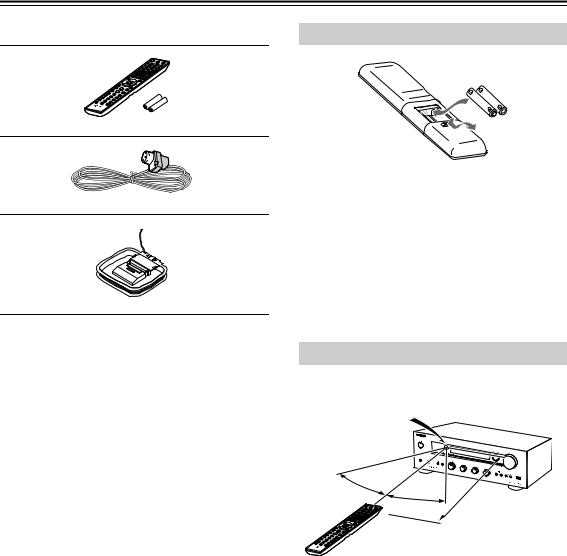
Supplied Accessories
Make sure you have the following accessories: |
Installing the Batteries |
|
Remote controller and two batteries (AAA/R03)
Indoor FM antenna
AM loop antenna
*In catalogs and on packaging, the letter at the end of the product name indicates the color. Specifications and operation are the same regardless of color.
Notes:
•If the remote controller doesn’t work reliably, try replacing the batteries.
•Don’t mix new and old batteries or different types of batteries.
•If you intend not to use the remote controller for a long time, remove the batteries to prevent damage from leakage or corrosion.
•Expired batteries should be removed as soon as possible to prevent damage from leakage or corrosion.
Aiming the Remote Controller
When using the remote controller, point it toward the receiver’s remote control sensor, as shown below.
Remote control sensor
TX-8050
30°
30° |
Approx. 5 m (16 ft.) |
|
En-6
Getting to Know the Receiver
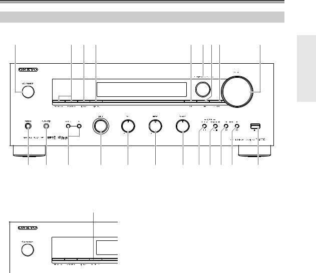
Front Panel
North American model
a |
2 3 4 |
5 678 |
9 |
|
|
j k l |
m n o p q r s t u |
||
European model
v |
For detailed information, see the pages in parentheses.
a ON/STANDBY button (18, 45, 51) |
l ZONE 2, OFF buttons (45) |
b SPEAKERS A and B switches (19) |
m INPUT selector (19, 22, 23, 27, 45) |
c DISPLAY button (25) |
n BASS control (20) |
d DIMMER button (North American model) (20) |
o TREBLE control (20) |
e SETUP button (12, 40, 44) |
p BALANCE control (20) |
f TUNING / , PRESET / buttons (23, 24, |
q MEMORY/MENU button (24) |
27, 40) |
r TUNING MODE/ / button (23, 25, 51) |
g ENTER button (27) |
s PRESET / button (24) |
h RETURN button (40) |
t PRESET / button (24) |
i VOLUME control (19) |
u USB port (28) |
|
|
j PHONES jack (19) |
v RT/PTY/TP button (European model) (27) |
|
|
k PURE AUDIO button and indicator (21) |
|
En-7

Getting to Know the Receiver—Continued
Rear Panel
a |
b c 4 |
5 6 |
|
7 |
8 9 |
jkl mno p |
q |
r |
|
For detailed information, see the pages in parentheses.
aREMOTE CONTROL jack (16)
bUNIVERSAL PORT jack (15)
cETHERNET port (15)
dMONITOR OUT jack (15)
ePRE OUT jacks (11)
fZONE 2 PRE OUT jacks (44)
gIR IN/OUT jacks (47)
hFM ANTENNA jack and AM ANTENNA terminal (13)
iDIGITAL IN COAXIAL and OPTICAL jacks (15)
jPHONO IN (MM) and GND terminal (15)
kCD IN jacks (15)
lTV/TAPE IN/OUT jacks (15, 17)
mGAME IN jacks (15)
nCBL/SAT IN jacks (15)
oVCR/DVR IN/OUT jacks (15, 17)
pBD/DVD IN jacks (15)
qSPEAKERS A terminals (10)
rSPEAKERS B terminals (10)
See “Connecting the Receiver” for connection ( pages 10 to 17).
Display |
|
|
|
abc |
45 |
6 |
7 |
|
8 |
|
9 jkl mn |
For detailed information, see the pages in parentheses.
aDIRECT indicator (21)
bZ 2 (Zone 2) indicator (45)
cA/B speaker indicator (19)
dM.Opt indicator (21)
e, indicators
fMessage area
gTuning indicators
•RDS indicator (European model) (26)
•AUTO indicator (23)
En-8
•TUNED indicator (23)
•FM STEREO indicator (23, 51)
hHeadphone indicator
iNET indicator (30, 31)
jMUTING indicator (51)
kVolume level (19)
lUSB indicator (28, 29)
mSLEEP indicator (20, 41)
nAudio input indicators
Getting to Know the Receiver—Continued
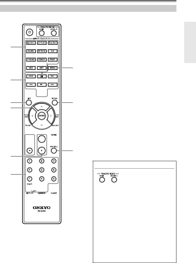
Remote Controller
For detailed information, see the pages in parentheses.
a
 n
n
b
o
3
4


 p
p
5 q
6
7


 r
r


 s 8
s 8


t
9
j
k


 u l
u l


 v m
v m
abutton (12, 18, 45)
bINPUT SELECTOR buttons (18, 19, 22, 23, 38, 39, 45)
cControl buttons (38, 39)
dREPEAT button (38, 39)
eLIST button
fArrow [ ]/[ ]/[ ]/[ ] and ENTER buttons
(12, 23, 38, 39, 40, 44)
gSETUP button (12, 40, 44)
hCH/ALBUM buttons (25, 38, 39)
iVOLUME / buttons (19, 46)
jNumber buttons (23, 24, 39)
k>10/CAPS/D.TUN button (24)
lDISPLAY button (25, 38, 39)
mDIMMER button (20)
nREMOTE MODE buttons (9, 39, 45, 46)
oMODE button (38, 39)
pRANDOM button (38, 39)
qMENU button (39)
rRETURN button (38, 39, 40)
sAUDIO button (21)
tMUTING button (19, 45, 46)
uCLR button (25)
vSLEEP button (20)
Using the REMOTE MODE buttons
You can use this remote
controller’s Zone 2 capability to control a Zone 2 device. To control a Zone 2 device, start by
pressing the REMOTE MODE [ZONE 2] button. After you’ve finished operating the Zone 2 device, and would like to operate this receiver once again, press the REMOTE MODE [MAIN] button.
If the expected operation does not occur even though the remote controller is pointed toward the receiver, it may be that Zone 2 is selected. Please press the REMOTE MODE [MAIN] button. Once you’ve pressed the REMOTE MODE [MAIN] button, there’s no need to press this button again before each operation; you can simply use the remote controller to operate the receiver as usual. Similarly, once you’ve pressed the REMOTE MODE [ZONE 2] button, you can continue operating the Zone 2 device without having to press this button again before each operation.
En-9
Connecting the Receiver
Disconnect the power cord from the electrical outlet before making any connections.
Speaker Connection Precautions
The receiver allows you to connect two sets of speakers. When two sets of speakers are connected, you can select which speaker set outputs sound or use both sets to output sound simultaneously. ( page 19 about “Speakers A” and “Speakers B”)
•When you connect one set of speakers to either SPEAKERS A or SPEAKERS B terminal posts, or when you connect two sets of speakers to both speaker terminal posts and output sound only from either
speaker set, use speakers whose impedance is 4 to 16 Ω, and set the speaker impedance setting on the receiver to 4 or 6 Ω ( page 12). When the impedance of the speaker to be used is less than 6 Ω, set the speaker impedance to 4 Ω.
•When you connect speakers to both SPEAKERS A and SPEAKERS B terminal posts and output sound
from both speaker sets simultaneously, use speakers whose impedance is 8 to 16 Ω. Set the speaker impedance setting on the receiver to 4 Ω.
•Read the instructions supplied with your speakers.
•Pay close attention to speaker wiring polarity. In other words, connect positive (+) terminals only to positive (+) terminals, and negative (–) terminals only to negative (–) terminals. If you get them the wrong way around, the sound will be out of phase and will sound unnatural.
•Unnecessarily long or very thin speaker cables may affect the sound quality and should be avoided.
•Be careful not to short the positive and negative wires. Doing so may damage the
receiver.
• Don’t connect more than one cable to each speaker terminal. Doing so may damage the receiver.
•Don’t connect a speaker to more than one pair of speaker terminals.
Note:
If you make an incorrect setting for the speakers or the impedance values, the built-in protection circuit may be activated resulting in no sound output from speakers.
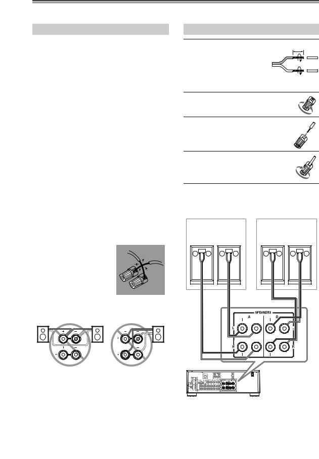
Connecting the Speaker Cables
Strip about 5/8" (15 mm) |
5/8" (15 mm) |
1 of insulation from the |
|
ends of the speaker |
|
cables, and twist the |
|
bare wires tightly, as |
|
shown. |
|
2 Unscrew the terminal. |
|
3 Fully insert the bare wire.
4 Screw the terminal tight.
The following illustration shows which speaker should be connected to each pair of terminals.
Speaker set A
Right Left speaker speaker
– |
+ |
– |
+ |
Speaker set B
Right Left speaker speaker
– |
+ |
– |
+ |
Receiver |
En-10
Connecting the Receiver—Continued
Connecting a Powered Subwoofer
Using a suitable cable, connect the receiver’s PRE OUT: SUBWOOFER to the input on your powered subwoofer. If your subwoofer is unpowered and you’re using an external amplifier, connect the PRE OUT: SUBWOOFER to the amp’s input.
Powered subwoofer
Connecting a Power Amplifier
If you want to use a more powerful power amplifier and use the receiver as a preamp, connect the receiver’s PRE OUT: L, R to the amp’s input, and connect all speakers to the power amplifier.
LINE IN
Power amplifier
– |
+ |
– |
+ |
|
Speakers |
|
|
En-11
Connecting the Receiver—Continued
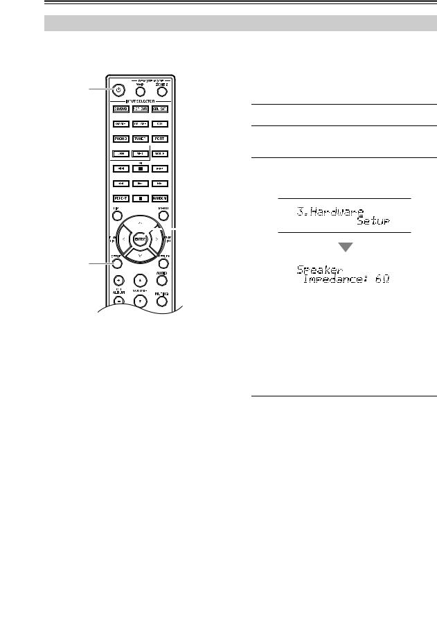
Configuring the Speaker Impedance
On the receiver, the factory default for speaker impedance is “6 Ω”. If you need to change the speaker impedance setting, read “Speaker Connection Precautions” on page 10 carefully before performing the procedure below.

 ENTER
ENTER
SETUP
Note:
Be sure to minimize the volume level on the receiver before configuring the speaker impedance.
1 Press the [ ] button to turn on the power.
2 Press the [SETUP] button on the remote controller.
3 Use the arrow [ ]/[ ] buttons to select
“3. Hardware Setup,” and then press [ENTER].
|
|
|
|
|
|
|
|
|
|
|
|
|
|
|
|
|
|
|
|
|
|
|
|
4 |
Change the impedance value to “4 Ω” using |
||||
|
the arrow [ ]/[ ] buttons. |
||||
|
|
|
|
|
|
5 |
Press the [SETUP] button on the remote |
||||
|
controller to complete the setting. |
||||
If you want to change the impedance setting back to the factory default setting of 6 Ω, follow the same procedure described above.
Notes:
•This procedure can also be performed on the receiver by using [SETUP], TUNING [ ]/[ ], PRESET [ ]/[ ], and ENTER.
•Press [RETURN] to return to the previous menu.
Setting example :
If you’re using only one of the speaker sets connected to SPEAKERS A or B, choose the 4 Ω setting if each speaker’s impedance is 4 Ω to less than 6 Ω, or choose the 6 Ω setting if each speaker’s impedance is 6 Ω or more.
If you’re using both of the speaker sets connected to SPEAKERS A and B, choose the 4 Ω setting if each speaker’s impedance is 8 to 16 Ω.
En-12
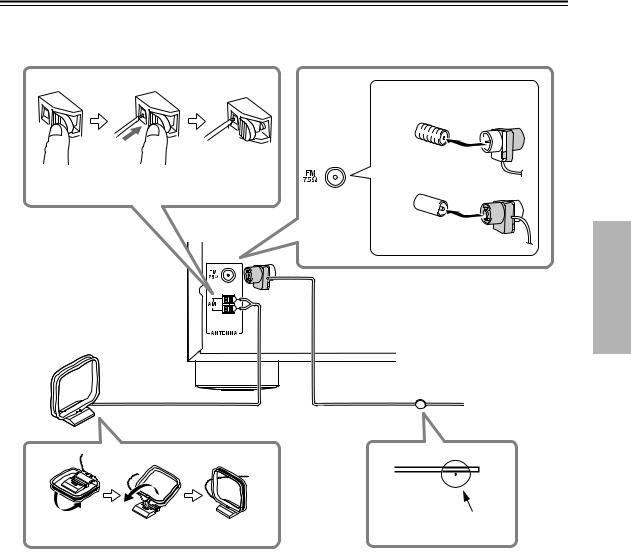
Connecting Antennas
This section explains how to connect the supplied indoor FM antenna and AM loop antenna.
The receiver won’t pick up any radio signals if no antenna is connected, so you must connect the antenna to use the tuner.
Insert the plug fully into the jack.
Nortn american model
Push |
Insert wire |
Release |
European model
AM loop antenna (supplied)
Indoor FM antenna (supplied)
Thumbtacks, etc.
Assembling the AM loop antenna
Caution:
Be careful that you don’t injure yourself when using thumbtacks.
Notes:
•Once your receiver is ready for use, you’ll need to tune into a radio station and position the antenna to achieve the best possible reception.
•Keep the AM loop antenna as far away as possible from your receiver, TV, speaker cables, and power cords.
•Refer to “Hardware Setup” on page 41 for more information on switching the frequency setup.
Tips:
•If you cannot achieve good reception with the supplied indoor FM antenna, try a commercially available outdoor FM antenna instead.
•If you cannot achieve good reception with the supplied indoor AM loop antenna, try using it with a commercially available outdoor AM antenna.
En-13

Connecting Your Components
About AV Connections
Connecting AV components
Video |
Receiver |
|
|
Audio |
|
Blu-ray Disc/
DVD player
TV, projector, etc. |
Game console |
•Before making any AV connections, read the manuals supplied with your AV components.
•Don’t connect the power cord until you’ve completed and double-checked all AV connections.
• Push plugs in all the way to make good connections |
|
|
|
|
|
|
|
|
Right! |
|
|
|
|
|
|
|
|||||
(loose connections can cause noise or malfunctions). |
|
|
|
|
|
|
|
|
|
|
|
|
|
|
|
|
|
|
|
|
|
|
|
|
|
|
|
|
|
|
|
|
|
|
|
|
|
|
|
|
|
|
|
 Wrong!
• To prevent interference, keep audio and video cables away from power cords and speaker cables.
AV Cables and Jacks
Signal |
Cable |
Jack |
|
Description |
Video |
Composite video |
V |
Yellow |
Composite video is commonly used on TVs, VCRs, and |
|
|
other video equipment. |
||
|
|
|
|
|
Audio |
Optical digital |
|
|
Optical digital connections allow you to enjoy digital sound. |
|
audio |
|
OPTICAL |
The audio quality is the same as coaxial. |
|
|
|
|
|
|
Coaxial digital |
COAXIAL |
Orange |
Coaxial digital connections allow you to enjoy digital sound . |
|
audio |
|
|
The audio quality is the same as optical. |
|
Analog audio |
L |
White |
Analog audio connections (RCA) carry analog audio. |
|
(RCA) |
|||
|
|
Red |
|
|
|
|
R |
|
|
|
|
|
|
Notes:
•The receiver does not support SCART plugs.
•The receiver does not support multichannel audio input. The PCM signal can be input only to digital input terminals. Make sure that PCM is selected on the playback component.
•The receiver’s optical digital jacks have shutter-type covers that open when an optical plug is inserted and close when it’s removed. Push plugs in all the way.
Caution:
To prevent shutter damage, hold the optical plug straight when inserting and removing.
En-14
Connecting Your Components—Continued
.
|
|
|
|
|
|
|
|
|
|
|
|
|
|
|
|
|
|
|
|
|
|
|
|
|
|
|
|
|
|
|
|
|
|
|
|
|
|
|
|
|
|
|
|
|
|
|
|
|
|
|
|
|
|
|
|
|
|
|
|
|
|
|
|
|
|
|
|
|
|
|
|
|
|
|
|
|
|
|
|
|
|
|
|
|
|
|
|
|
|
|
|
|
|
|
|
|
|
|
|
|
|
|
|
|
|
|
|
|
|
|
|
|
|
|
|
|
|
|
|
|
|
|
|
|
|
|
|
|
|
|
|
|
|
|
|
|
|
|
|
|
|
|
|
|
|
|
|
|
|
|
|
|
|
|
|
|
|
|
|
|
|
|
|
|
|
|
|
|
|
|
|
|
|
|
|
|
|
|
|
|
|
|
|
|
|
|
|
|
|
|
|
|
|
|
|
|
|
|
|
|
|
|
|
|
|
|
|
|
|
|
|
|
|
|
|
|
|
|
|
|
|
|
|
|
|
|
|
|
|
|
|
|
|
|
|
|
|
|
|
|
|
|
|
|
|
|
|
|
|
|
|
|
|
|
|
|
|
|
|
|
|
|
|
|
|
|
|
|
|
|
|
|
|
|
|
|
|
|
|
|
|
|
|
|
|
|
|
|
|
|
|
|
|
|
|
|
|
|
|
|
|
|
|
|
|
|
|
|
|
|
|
|
|
|
|
|
|
|
|
|
|
|
|
|
|
|
|
|
|
|
|
|
|
|
|
|
|
|
|
|
|
|
|
|
|
|
|
|
|
|
|
|
|
|
|
|
|
|
|
|
|
|
|
|
|
|
|
|
|
|
|
|
|
|
|
|
|
|
|
|
|
|
|
|
|
|
|
|
|
|
|
|
|
|
|
|
|
|
|
|
|
|
|
|
|
|
|
|
|
|
|
|
|
|
|
|
|
|
|
|
|
|
|
|
|
|
|
|
|
|
|
|
|
|
|
|
|
|
|
|
|
|
|
|
|
|
|
|
|
|
|
|
|
|
|
|
|
|
|
|
|
|
|
|
|
|
|
|
|
|
|
|
|
|
|
|
|
|
|
|
|
|
|
|
|
|
|
|
|
|
|
|
|
|
|
|
|
|
|
|
|
|
|
|
|
|
|
|
|
|
|
|
|
|
|
|
|
|
|
|
|
|
|
|
|
|
|
|
|
|
|
|
|
|
|
|
|
|
|
|
|
|
|
|
|
|
|
|
|
|
|
|
|
|
|
|
|
|
|
|
|
|
|
|
|
|
|
|
|
|
|
|
|
|
|
|
|
|
|
|
|
|
|
|
|
|
|
|
|
|
|
|
|
|
|
|
|
|
|
|
|
|
|
|
|
|
|
|
|
|
|
|
|
|
|
|
|
|
|
|
|
|
|
|
|
|
|
|
|
|
|
|
|
|
|
|
|
|
|
|
|
|
|
|
|
|
|
|
|
|
|
|
|
|
|
|
|
|
|
|
|
|
|
|
|
|
|
|
|
|
|
|
|
|
|
|
|
|
|
|
|
|
|
|
|
|
|
|
|
|
|
|
|
|
|
|
|
|
|
|
|
|
|
|
|
|
|
|
|
|
|
|
|
|
|
|
|
|
|
|
|
|
|
|
|
|
|
|
|
|
|
|
|
|
|
|
|
|
|
|
|
|
|
|
|
|
|
|
|
|
|
|
|
|
|
|
|
|
|
|
|
|
|
|
|
|
|
|
|
|
|
|
|
|
|
|
|
|
|
|
|
|
|
|
|
|
|
|
|
|
|
|
|
|
|
|
|
|
|
|
|
|
|
|
|
|
|
|
|
|
|
|
|
|
|
|
|
|
|
|
|
|
|
|
|
|
|
|
|
|
|
|
|
|
|
|
|
|
|
|
|
|
|
|
|
|
|
|
|
|
|
|
|
|
|
|
|
|
|
|
|
|
|
|
|
|
|
|
|
|
|
|
|
|
|
|
|
|
|
|
|
|
|
|
|
|
|
|
|
|
|
|
|
|
|
|
|
|
|
|
|
|
|
|
|
|
|
|
|
|
|
|
|
|
|
|
|
|
|
|
|
|
|
|
|
|
|
|
|
|
|
|
|
|
|
|
|
|
|
|
|
|
|
|
|
|
|
|
|
|
|
|
|
|
|
|
|
|
|
|
|
|
|
|
|
|
|
|
|
|
|
|
|
|
|
|
|
|
|
|
|
|
|
|
|
|
|
|
|
|
|
|
|
|
|
|
|
|
|
|
|
|
|
|
|
|
|
|
|
|
|
|
|
|
|
|
|
|
|
|
|
|
|
|
|
|
|
|
|
|
|
|
|
|
|
|
|
|
|
|
|
|
|
|
|
|
|
|
|
|
|
|
|
|
|
|
|
|
|
|
|
|
|
|
|
|
|
|
|
|
|
|
|
|
|
|
|
|
|
|
|
|
|
|
|
|
|
|
|
|
|
|
|
|
|
|
|
|
|
|
|
|
|
|
|
|
|
|
|
|
|
|
|
|
|
|
|
|
|
|
|
|
|
|
|
|
|
|
|
|
|
|
|
|
|
|
|
|
|
|
|
|
|
|
|
|
|
|
|
|
|
|
|
|
|
|
|
|
|
|
|
|
|
|
|
|
|
|
|
|
|
|
|
|
|
|
|
|
|
|
|
|
|
|
|
|
|
|
|
|
|
|
|
|
|
|
|
|
|
|
|
|
|
|
|
|
|
|
|
|
|
|
|
|
|
|
|
|
|
|
|
|
|
|
|
|
|
|
|
|
|
|
|
|
|
|
|
|
|
|
|
|
|
|
|
|
|
|
|
|
|
|
|
|
|
|
|
|
|
|
|
|
|
|
|
|
|
|
|
|
|
|
|
|
|
|
|
|
|
|
|
|
|
|
|
|
|
|
|
|
|
|
|
|
|
|
|
|
|
|
|
|
|
|
|
|
|
|
|
|
|
|
|
|
|
|
|
|
|
|
|
|
|
|
|
|
|
|
|
|
|
|
|
|
|
|
|
|
|
|
|
|
|
|
|
|
|
|
|
|
|
|
|
|
|
|
|
|
|
|
|
|
|
|
|
|
|
|
|
|
|
|
|
|
|
|
|
|
|
|
|
|
|
|
|
|
|
|
|
|
|
|
|
|
|
|
|
|
|
|
|
|
|
|
|
|
|
|
|
|
|
|
|
|
|
|
|
|
|
|
|
|
|
|
|
|
|
|
|
|
|
|
|
|
|
|
|
|
|
|
|
|
|
|
|
|
|
|
|
|
|
|
|
|
|
|
|
|
|
|
|
|
|
|
|
|
|
|
|
|
|
|
|
|
|
|
|
|
|
|
|
|
|
|
|
|
|
|
|
|
|
|
|
|
|
|
|
|
|
|
|
|
|
|
|
|
|
|
|
|
|
|
|
|
|
|
|
|
|
|
|
|
|
|
|
|
|
|
|
|
|
|
|
|
|
|
|
|
|
|
|
|
|
|
|
|
|
|
|
|
|
|
|
|
|
|
|
|
|
|
|
|
|
|
|
|
|
|
|
|
|
|
|
|
|
|
|
|
|
|
|
|
|
|
|
|
|
|
|
|
|
|
|
|
|
|
|
|
|
|
|
|
|
|
|
|
|
|
|
|
|
|
|
|
|
|
|
|
|
|
|
|
|
|
|
|
|
|
|
|
|
|
|
|
|
|
|
|
|
|
|
|
|
|
|
|
|
|
|
|
|
|
|
|
|
|
|
|
|
|
|
|
|
|
|
|
|
|
|
|
|
|
|
|
|
|
|
|
|
|
|
|
|
|
|
|
|
|
|
|
|
|
|
|
|
|
|
|
|
|
|
|
|
|
|
|
|
|
|
|
|
|
|
|
|
|
|
|
|
|
|
|
|
|
|
|
|
|
|
|
|
|
|
|
|
|
|
|
|
|
|
|
|
|
|
|
|
|
|
|
|
|
|
|
|
|
|
|
|
|
|
|
|
|
|
|
|
|
|
|
|
|
|
|
|
|
|
|
|
|
|
|
|
|
|
|
|
|
|
|
|
|
|
|
|
|
|
|
|
|
|
|
|
|
|
|
|
|
|
|
|
|
|
|
|
|
|
|
|
|
|
|
|
|
|
|
|
|
|
|
|
|
|
|
|
|
|
|
|
|
|
|
|
|
|
|
|
|
|
|
|
|
|
|
|
|
|
|
|
|
|
|
|
|
|
|
|
|
|
|
|
|
|
|
|
|
|
|
|
|
|
|
|
|
|
|
|
|
|
|
|
|
|
|
|
|
|
|
|
|
|
|
|
|
|
|
|
|
|
|
|
|
|
|
|
|
|
|
|
|
|
|
|
|
|
|
|
|
|
|
|
|
|
|
|
|
|
|
|
|
|
|
|
|
|
|
|
|
|
No. |
Jack/Port |
|
|
|
|
|
|
|
|
|
Connectable components |
|
|
||||||||||||||||||||||||||||||||||||||||||||||||||||||||||||||||
|
|
|
|
|
|
|
|
|
|
|
|
|
|
|
|
|
|
|
|
|
|
|
|
|
|||||||||||||||||||||||||||||||||||||||||||||||||||||
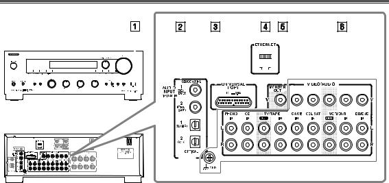
1 |
|
|
|
USB |
|
|
|
|
|
|
|
|
|
iPod/iPhone, MP3 player, USB flash drive |
|
|
|||||||||||||||||||||||||||||||||||||||||||||||||||||||||||||
|
|
|
|
|
|
|
|
|
|
|
|
|
|
|
|
|
|
|
|
|
|
|
|||||||||||||||||||||||||||||||||||||||||||||||||||||||
2 |
|
|
|
DIGITAL IN |
OPTICAL |
1 (GAME) |
|
Game console |
|
|
|||||||||||||||||||||||||||||||||||||||||||||||||||||||||||||||||||
|
|
|
|
|
|
|
|
|
|
|
|
|
|
|
|
|
|
|
|
|
|
|
|
2 (CD) |
|
TV, CD player |
|
|
|||||||||||||||||||||||||||||||||||||||||||||||||
|
|
|
|
|
|
|
|
|
|
|
|
|
|
|
|
|
|
|
|
|
|
|
|
|
|||||||||||||||||||||||||||||||||||||||||||||||||||||
|
|
|
|
|
|
|
|
|
|
|
|
|
|
|
|
|
|
|
|
|
|
|
|
|
|
|
|
|
|
|
|
|
|
||||||||||||||||||||||||||||||||||||||||||||
|
|
|
|
|
|
|
|
|
|
|
|
|
|
|
|
|
|
|
|
|
|
COAXIAL |
1 (BD/DVD) |
|
Blu-ray Disc/DVD player |
|
|
||||||||||||||||||||||||||||||||||||||||||||||||||
|
|
|
|
|
|
|
|
|
|
|
|
|
|
|
|
|
|
|
|
|
|
|
|
|
|
|
|
|
|
|
|
|
|
||||||||||||||||||||||||||||||||||||||||||||
|
|
|
|
|
|
|
|
|
|
|
|
|
|
|
|
|
|
|
|
|
|
|
|
2 (CBL/SAT) |
|
Satellite/cable set-top box, RI dock, etc. |
|
|
|||||||||||||||||||||||||||||||||||||||||||||||||
|
|
|
|
|
|
|
|
|
|
|
|
|
|
|
|
|
|
|
|
|
|
|
|
|
|
||||||||||||||||||||||||||||||||||||||||||||||||||||
3 |
|
|
|
UNIVERSAL PORT |
|
|
|
|
|
|
|
|
|
Universal port option dock (UP-A1 etc.) |
|
|
|||||||||||||||||||||||||||||||||||||||||||||||||||||||||||||
|
|
|
|
|
|
|
|
|
|
|
|
|
|
|
|
|
|
|
|
|
|
|
|
|
|||||||||||||||||||||||||||||||||||||||||||||||||||||
4 |
|
|
|
ETHERNET |
|
|
|
|
|
|
|
|
|
Router |
|
|
|||||||||||||||||||||||||||||||||||||||||||||||||||||||||||||
|
|
|
|
|
|
|
|
|
|
|
|
|
|
|
|
|
|
|
|
|
|
|
|
|
|||||||||||||||||||||||||||||||||||||||||||||||||||||
5 |
|
|
|
MONITOR OUT |
|
|
|
|
|
|
|
|
|
TV, projector, etc. |
|
|
|||||||||||||||||||||||||||||||||||||||||||||||||||||||||||||
|
|
|
|
|
|
|
|
|
|
|
|
|
|
|
|
|
|
|
|
|
|
|
|
|
|||||||||||||||||||||||||||||||||||||||||||||||||||||
6 |
|
|
|
BD/DVD IN |
|
|
|
|
|
|
|
|
|
Blu-ray Disc/DVD player |
|
|
|||||||||||||||||||||||||||||||||||||||||||||||||||||||||||||
|
|
|
|
|
|
|
VCR/DVR IN |
|
|
|
|
|
|
|
|
|
VCR or DVD recorder/digital video recorder, RI dock |
|
|
||||||||||||||||||||||||||||||||||||||||||||||||||||||||||
|
|
|
|
|
|
|
|
|
|
|
|
|
|
|
|
|
|
|
|
|
|
|
|
|
|
||||||||||||||||||||||||||||||||||||||||||||||||||||
|
|
|
|
|
|
|
CBL/SAT IN |
|
|
|
|
|
|
|
|
|
Satellite/cable set-top box, etc. |
|
|
||||||||||||||||||||||||||||||||||||||||||||||||||||||||||
|
|
|
|
|
|
|
|
|
|
|
|
|
|
|
|
|
|
|
|
|
|
|
|
|
|
||||||||||||||||||||||||||||||||||||||||||||||||||||
|
|
|
|
|
|
|
GAME IN |
|
|
|
|
|
|
|
|
|
Game console, RI dock |
|
|
||||||||||||||||||||||||||||||||||||||||||||||||||||||||||
|
|
|
|
|
|
|
|
|
|
|
|
|
|
|
|
|
|
|
|
|
|
|
|
|
|
||||||||||||||||||||||||||||||||||||||||||||||||||||
|
|
|
|
|
|
|
TV/TAPE IN |
|
|
|
|
|
|
|
|
|
TV, cassette tape deck, RI dock |
|
|
||||||||||||||||||||||||||||||||||||||||||||||||||||||||||
|
|
|
|
|
|
|
|
|
|
|
|
|
|
|
|
|
|
|
|
|
|
|
|
|
|
||||||||||||||||||||||||||||||||||||||||||||||||||||
|
|
|
|
|
|
|
CD IN |
|
|
|
|
|
|
|
|
|
CD player, Turntable |
|
|
||||||||||||||||||||||||||||||||||||||||||||||||||||||||||
|
|
|
|
|
|
|
|
|
|
|
|
|
|
|
|
|
|
|
|
|
|
|
|
|
|
||||||||||||||||||||||||||||||||||||||||||||||||||||
|
|
|
|
|
|
|
PHONO IN |
|
|
|
|
|
|
|
|
|
Turntable |
|
|
||||||||||||||||||||||||||||||||||||||||||||||||||||||||||
|
|
|
|
|
|
|
|
|
|
|
|
|
|
|
|
|
|
|
|
|
|
|
|
|
|
|
|
|
|
|
|
|
|
|
|
|
|
|
|
|
|
|
|
|
|
|
|
|
|
|
|
|
|
|
|
|
|
|
|
|
|
|
|
|
|
|
|
|
|
|
|
|
|
|
|
|
|
Notes:
•Refer to the connected component’s instruction manual for details.
•Do not connect the receiver’s USB port to a USB port on your computer. Music on your computer cannot be played through the receiver in this way.
•Connect a turntable (MM) that has a built-in phono preamp to CD IN, or connect it to PHONO IN with the phono preamp turned off. If your turntable (MM) doesn’t have a phono preamp, connect it to PHONO IN. If your turntable has a moving coil (MC) type cartridge, you’ll need a commercially available MC head amp or MC transformer to connect to PHONO IN. See your turntable’s manual for details. If your turntable has a ground wire, connect it to the GND screw. With some turntables, connecting the ground wire may produce an audible hum. If this happens, disconnect it.
•Connection 3and 6lets you listen to and record audio from the external components while you are in Zone 2. You can listen to and record audio from the external components in the main room; you can listen to the audio in Zone 2 as well.
•If your Blu-ray Disc/DVD player has both main stereo and multichannel outputs, be sure to connect the main stereo output using connection 6.
■ How to record a video source
See “Recording” to make connections for video recording ( page 22).
En-15
Connecting Your Components—Continued
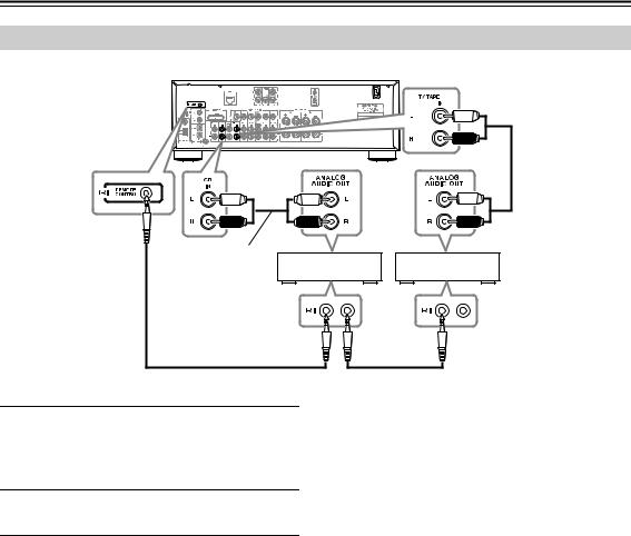
Connecting Onkyo Components
Analog audio cable
Analog |
|
|
audio cable |
e.g., CD player |
e.g., Tape deck |
|
cable |
cable |
1 Make sure that each Onkyo component is connected with an analog audio cable (connection 6 in the hookup examples) ( page 15).
2 Make the connection (see the illustration).
With (Remote Interactive), you can use the following special functions:
■ System On/Auto Power On
•Connect only Onkyo components to jacks. Connecting other manufacturer’s components may cause a malfunction.
•Some components may not support all functions. Refer to the manuals supplied with your Onkyo components.
•While Zone 2 is on, the System On/Auto Power On and Direct Change functions do not work.
When you start playback on a component connected via, while the receiver is on Standby, the receiver will automatically turn on and select that component as the input source.
■ Direct Change
When playback is started on a component connected via, the receiver automatically selects that component as the input source.
■ Remote Control
You can use the receiver’s remote controller to control your other -capable Onkyo components, pointing the remote controller at the receiver’s remote control sensor instead of the component.
Notes:
•Use only cables for connections. cables are supplied with Onkyo players (CD, etc.).
•Some components have two jacks. You can connect either one to the receiver. The other jack is for connecting additional -capable components.
En-16
Connecting Your Components—Continued
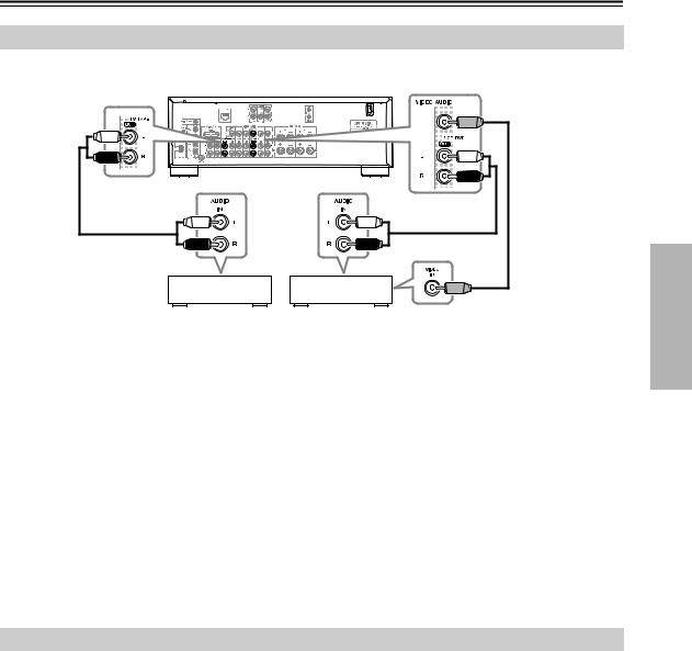
Connecting a Recording Component
See “Recording” for an explanation of recording ( page 22).
Analog |
Analog |
Composite video |
cable |
||
audio cable |
audio cable |
|
Cassette tape |
VCR, DVD recorder, etc. |
deck, CDR, etc.
Notes:
•The receiver must be turned on for recording. Recording is not possible while it’s in Standby mode.
•If you want to record directly from your TV or playback VCR to the recording VCR without going through the receiver, connect the TV/VCR’s audio and video outputs directly to the recording VCR’s audio and video inputs. See the manuals supplied with your TV and VCR for details.
•Video signals connected to composite video inputs can be recorded only via composite video outputs. If your TV/VCR is connected to a composite video input, the recording VCR must be connected to a composite video output.
•Copy-protected Blu-ray discs and DVDs cannot be recorded.
•Sources connected to a digital input cannot be recorded. Only analog inputs can be recorded.
•DTS signals will be recorded as noise, so don’t attempt analog recording of DTS CDs or LDs.
•If Pure Audio is turned on, no video signal is output from the receiver. If you want to make recordings, select another listening mode.
Connecting the Power Cord
Connect the receiver’s power cord to a suitable wall outlet.
Notes:
•Before connecting the power cord, connect all of your speakers and AV components.
•Turning on the receiver may cause a momentary power surge that might interfere with other electrical equipment on the same circuit. If this is a problem, plug the receiver into a different branch circuit.
En-17
Loading...