


 Loading...
TA-RW544/344
Ster eo Cassette Tape Deck
Instruction Manual
EJECT |
DECK A/B RESET |
EJECT |
DECK A |
|
DECK B |
2 MOTER COMPUTER CONTROL |
DUBB. STOP |
2 MOTER COMPUTER CONTROL |
|
||
AUTO REVERSE |
|
AUTO REVERSE |
//
POWER |
PHONES REVERSE MODE |
DUBBING |
REC BALANCE |
REC LEVEL |
||
|
|
NORMAL HIGH |
|
|
|
|
|
DOLBY NR |
|
|
|
|
|
ON OFF |
|
|
L |
R |
MIN |
MAX |
STEREO CASSETTE TAPE DECK TA-RW544
CONTENTS
Features ................................................ |
2 |
Important Safeguards ........................... |
3 |
Precautions .......................................... |
3 |
Control Positions and Names .............. |
4 |
Setting the Voltage Selector ................ |
5 |
System Connections ............................ |
5 |
Power Connections .............................. |
5 |
To Play a Tape ..................................... |
6 |
Useful Functions Available during Playback |
|
(TA-RW544 Only) .............................................. |
7 |
Recording ............................................ |
8 |
Tape Dubbing .................................... |
12 |
Useful Recording Functions .............. |
13 |
Making Good Sound Recordings ...... |
13 |
Connecting ONKYO Components |
|
for z Components ........................... |
14 |
CD Synchro Recording System ......... |
14 |
Reverse Mode Function ..................... |
15 |
Handling Cassette Tapes ................... |
16 |
Cassette Deck Maintenance ............... |
17 |
Specifications .................................... |
17 |
Troubleshooting Guide ...................... |
18 |
1
Thank you for your purchase of the
ONKYO TA-RW544/344 Cassette Tape Deck.
Please read this manual thoroughly before making connections and plugging in the AC power cord.
Following the instructions in this manual will enable you to obtain optimum performance and maximum listening enjoyment from your new TA-RW544/344.
Please retain this manual for future reference.
Features
Convenient dubbing & nonstop music
Excellent performance is not this deck’s singular feature. The TA-RW544 is two outstanding recording decks in one. So you can make a copy for yourself and one for a friend at the same time. Or keep recording or playing tape after tape with its dual auto reverse (to capture and enjoy those longer shows).
Rugged 2 x 2 motor transport system
Separate capstan and reel motors for each transport not only prevent overloading, they provide the precise tape movement needed for accurate reproduction. They also contribute to the long-life, trouble-free performance that ONKYO cassette decks are famous for.
Dolby HX Pro headroom extension
Dolby HX Pro extends the dynamic headroom to capture the wider musical dynamics of CDs and other digital sources. It provides noticeably cleaner reproduction of those crucial higher frequencies by improving the tape’s ability to capture high-level signals without saturation. Another plus is the tapes you record with Dolby HX Pro can be played back on decks without Dolby HX Pro, for improved sound performance.
Music search (TA-RW544 only)
When you’re playing a tape back, our Music Search system does just what you might expect—lets you automatically skip forward or backward to easily find the exact beginning
of each selection. It works by sensing pauses between music selections.
One-touch CD synchronized recording
This handy feature lets you effortlessly and accurately record your favorite CDs when your deck is connected to virtually any z compatible ONKYO CD player.
z (Remote Interactive) system compatible
As might be expected, the TA-RW544/344 is fully compatible with ONKYO’s z (Remote Interactive) system. This means you can control virtually all of the cassette deck’s major functions with other ONKYO remote controls.
Other features
•Auto tape selector: Automatically sets bias and equalization for the type of tape you insert.
•Auto spacing: Handy for inserting blank spaces when rerecording or editing tapes, or recording from CDs, records and the radio.
•Headphone jack: For private listening.
•Full repeat: Repeats both A and B sides of both transports up to eight times, then shuts off automatically.
• 8-segment fluorescent peak metering: Allows you to accurately adjust recording levels for optimum performance.
Declaration of Conformity
We, ONKYO EUROPE ELECTRONICS GMBH INDUSTRIESTRASSE 18/20 82110 GERMERING, GERMANY
declare in own responsibility, that the ONKYO product described in this instruction manual is in compliance with the corresponding technical standards such as EN55013, EN55020, EN60555-2, -3 and EN60065
GERMERING,GERMANY
H. YAMAZOE
ONKYO EUROPE ELECTRONICS GMBH
FOR CANADIAN MODEL: (POUR LE MODELE CANADIEN)
• For models having a power cord with a polarized plug CAUTION: TO PREVENT ELECTRIC SHOCK, MATCH
WIDE BLADE OF PLUG TO WIDE SLOT, FULLY INSERT.
• Sur les modèles dont la fiche est polarisée. ATTENTION: POUR ÉVITER LES CHOCS
ÉLECTRIQUES, INTRODUIRE LA LAME LA PLUS LARGE DE LA FICHE DANS LA BORNE CORRESPONDANTE DE LA PRISE ET POUSSER JUSQ’AU FOND.
ATTENTION FOR BRITISH MODEL
•Replacement and mounting of an AC plug on the power supply cord of this unit should be performed only by qualified service personnel.
•IMPORTANT: The wires in the mains lead are coloured in accordance with the following code:
Blue: Neutral
Brown: Live
As the colours of the wires in the mains lead of this apparatus may not correspond with the coloured markings identifying the terminals in your plug, proceed as follows:
The wire which is coloured blue must be connected to the terminal which is marked with the letter N or coloured black. The wire which is coloured brown must be connected to the terminal which is marked with the letter L or coloured red.
IMPORTANT
A 5 amp fuse is fitted in this plug. Should the fuse need to be replaced, please ensure that the replacement fuse has a rating of 5 amps and that it is approved by ASTA or BSI to BS1362. Check for the ASTA mark or the BSI mark on the body of the fuse.
IF THE FITTED MOULDED PLUG IS UNSUITABLE FOR THE SOCKET OUTLET IN YOUR HOME THEN THE FUSE SHOULD BE REMOVED AND THE PLUG CUT OFF AND DISPOSED OF SAFELY. THERE IS A DANGER OF SEVERE ELECTRICAL SHOCK IF THE CUT OFF PLUG IS INSERTED INTO ANY 13 AMP SOCKET.
Supplied accessory
Audio connection cable
WARNING
“TO REDUCE THE RISK OF FIRE OR ELECTRIC SHOCK, DO NOT EXPOSE THIS APPLIANCE TO RAIN OR MOISTURE.”
CAUTION
“TO REDUCE THE RISK OF ELECTRIC SHOCK, DO NOT REMOVE COVER (OR BACK). NO USER-SERV- ICEABLE PARTS INSIDE. REFER SERVICING TO QUALIFIED SERVICE PERSONNEL.”
CAUTION
RISK OF ELECTRIC SHOCK
DO NOT OPEN
•The lightning flash with arrowhead symbol, within an equilateral triangle, is intended to alert the user to the presence of uninsulated “dangerous voltage” within the product’s enclosure that may be of sufficient magnitude to constitute a risk of electric shock to persons.
•The exclamation point within an equilateral triangle is intended to alert the user to the presence of important operating and maintenance (servicing) instructions in the literature accompanying the appliance.
2

Important Safeguards
1.Read Instructions — All the safety and operating instructions should be read before the appliance is operated.
2.Retain Instructions — The safety and operating instructions should be retained for future reference.
3.Heed Warnings — All warnings on the appliance and in the operating instructions should be adhered to.
4.Follow Instructions — All operating and use instructions should be followed.
5.Water and Moisture — The appliance should not be used near water — for example, near a bathtub, washbowl, kitchen sink, laundry tub, in a wet basement, or near a swimming pool, and the like.
6.Carts and Stands — The appliance should be used only with a cart or stand that is recommended by the manufacturer.
6A. An appliance and cart combination should be moved with care. Quick stops, excessive force, and uneven surface may cause the appliance and cart combination to overturn.
PORTABLE CART WARNING
S3125A |
|
7. Wall or Ceiling Mounting — |
The appliance should be mounted |
to a wall or ceiling only as recommended by the manufacturer.
8.Ventilation – The appliance should be situated so that its location or position does not interfere with its proper ventilation. For example, the appliance should not be situated on a bed, sofa, rug, or similar surface that may block the ventilation openings; or if placed in a built-in installation, such as a book case or cabinet that may impede the flow of air through the ventilation openings, there should be free space of at least 20 cm (8 in.) and open up behind the appliance.
9.Heat — The appliance should be situated away from heat sources such as radiators, heat registers, stoves, or other appliances (including amplifiers) that produce heat.
10.Power Sources — The appliance should be connected to a power supply only of the type described in the operating instructions or as marked on the appliance.
11.Polarization — The polarization of the plug is a safety feature. The polarized plug will only fit the outlet one way. If the plug does not fit fully into the outlet, try reversing it. If there is still trouble inserting it, the user should seek the services of a qualified electrician. Under no circumstances should the user attempt to defeat the polarization of the plug.
12.Power-Cord Protection — Power-supply cords should be routed so that they are not likely to be walked on or pinched by items placed upon or against them, especially near plug, convenience receptacles, and the point where they exit from the appliance.
13.Cleaning — The appliance should be cleaned only as recommended by the manufacturer.
14.Nonuse Periods — The power cord of the appliance should be unplugged from the outlet when left unused for a long period of time.
15.Object and Liquid Entry — Care should be taken so that objects do not fall and liquids are not spilled into the enclosure through openings.
16. Damage Requiring Service — The appliance should be serviced by qualified service personnel when:
A.The power-supply cord or the plug has been damaged; or
B.Objects have fallen, or liquid has been spilled into the appliance; or
C.The appliance has been exposed to rain; or
D.The appliance does not appear to operate normally or exhibits a marked change in performance; or
E.The appliance has been dropped, or the enclosure damaged.
17.Servicing — The user should not attempt to service the appliance beyond that described in the operating instructions. All other servicing should be referred to qualified service personnel.
Precautions
1. Warranty Claim
You can find the serial number on the rear panel of the unit. In case of warranty claim, please report this number.
2. Recording Copyright
Recording of copyrighted material for other than personal use is illegal without permission of the copyright holder.
3.Deck Location
•Do not use or leave in direct sunlight or in other places subject to high temperature and humidity. The unit should also not be left in potentially hot places such as near heating appliances. Excessive heat and moisture can lead to internal damage and serious malfunctions. (This also applies to
cassette tapes.) The recommended ambient temperature range is 5°C to 35°C.
•Avoid damp and dusty places and locations prone to vibrations.
•Be extremely careful with the recording/playback heads. Clean and demagnetize them regularly, but under no circumstances should magnets or other metals be used anywhere near the heads.
•This unit is extremely sensitive to magnetic fields, so do not use near large speakers or other devices which generate magnetic fields.
•Hum may even be included by magnetic flux leakage from the power transformer in certain amplifiers. Therefore, this unit should also be kept clear of the amplifier.
•Do not remove the cabinet case. If any of the internal parts are handled, there is a considerable danger of electric shock.
4.Cassettes to Avoid:
•Cassettes with poorly formed cases that rattle during rewind and fast forward.
•Low cost cassettes with no guide roller or pressure pad spring should never be used for stereo.
•C-120 cassettes — because the tape and the coating are extremely thin, distortion levels are high. Also, even a slight stretching of the tape will make it susceptible to being caught up in the pinch roller and capstan.
•Endless tapes, if used for a long period of time, can overheat.
5.Power WARNING
BEFORE PLUGGING IN THE UNIT FOR THE FIRST TIME, READ THE FOLLOWING SECTION CAREFULLY.
• Some models are designed for use only with the power
supply voltage of the region where they are sold.
European and Australian models: |
AC 230 V, 50 Hz |
U.S.A. and Canadian models: |
AC120 V, 60 Hz |
Worldwide model: |
AC 120/220-230 V |
|
switchable, 50/60 Hz |
• Voltage Selector (Rear Panel)
The worldwide model is equipped with a voltage selector to conform with local power supplies. Be sure to set this switch to match the voltage of the power supply in your area before plugging in the unit. (See “Setting the Voltage Selector [Worldwide Model Only]” on page 5.) Models without a voltage selector can only be used in areas where the power supply voltage is the same as that of the unit.
Dolby noise reduction and HX Pro headroom extension manufactured under license from Dolby Laboratories Licensing Corporation. HX Pro originated by Bang & Olufsen. “Dolby,” the double-D symbol and “HX PRO” are trademarks of Dolby Laboratories Licensing Corporation.
3

Control Positions and Names |
|
|
|
||||||||||
|
|
|
|
|
|
|
|
|
|
|
If there is a protective film on the surface of |
||
|
|
|
|
|
|
5. DECK A/B |
|
|
the display, which makes it difficult to read |
||||
|
|
|
|
|
|
|
|
the display, remove it. |
|||||
|
|
|
|
|
|
|
6. RESET |
|
|
||||
|
|
|
|
|
|
|
|
|
For more information about a button or |
||||
|
|
|
|
|
4 |
|
|
7. EJECT |
|
|
|||
|
|
|
|
|
|
|
|
|
control, turn to the page number listed in |
||||
|
|
|
3. EJECT |
|
|
|
8 |
|
|
||||
|
|
|
|
|
|
|
|
square brackets ([ ]). |
|||||
|
|
1 |
2 |
|
|
|
|
|
9 |
|
|||
|
|
|
|
|
|
|
|
|
|
|
|||
|
|
|
|
EJECT |
|
DECK A/B |
RESET |
EJECT |
|
|
Front panel |
||
|
|
|
DECK A |
|
|
|
|
|
|
DECK B |
1. |
Deck A cassette holder |
|
|
|
2 MOTER COMPUTER CONTROL |
|
|
|
|
DUBB. STOP |
2 MOTER COMPUTER CONTROL |
|
2. |
Deck A operation buttons |
||
|
|
|
|
|
|
|
|
|
a : Reverse play button [6] |
||||
|
|
AUTO REVERSE |
|
/ |
|
/ |
|
|
AUTO REVERSE |
|
|
||
|
|
|
|
POWER PHONES |
DOLBY NR |
DUBBING |
REC BALANCE |
REC LEVEL |
|
|
|
e |
: Stop button [6,9] |
|
|
|
|
REVERSE MODE |
|
|
|
|
|
||||
|
|
|
|
|
NORMAL HIGH |
|
|
|
|
|
s : Forward play button |
||
|
|
|
|
ON OFF |
|
|
L R MIN MAX |
STEREO CASSETTE TAPE DECK TA-RW544 |
|
||||
|
|
|
|
|
|
|
|
|
|
|
|
|
[6,9,10,11] |
|
16. POWER |
|
|
|
|
10. REC LEVEL |
|
t : Rec/pause button [9,10,11] |
|||||
|
|
15. PHONES |
|
|
|
11. REC BALANCE |
|
(TA-RW544 only) |
|||||
|
|
|
|
|
|
d: Rewind button [7] |
|||||||
|
|
|
|
|
(TA-RW544 only) |
|
|||||||
|
|
|
|
|
|
|
|
|
|||||
|
|
14. DOLBY NR |
|
|
12. DUBBING |
|
|
f: Fast forward button [7] |
|||||
|
|
|
|
13. REVERSE MODE |
|
|
3. |
Deck A EJECT button [6,8] |
|||||
|
|
|
|
|
|
4. |
Display |
||||||
|
|
|
|
|
|
|
|
|
|
|
|||
(TA-RW544) |
|
|
|
|
|
|
|
|
|
|
5. |
DECK A/B counter button |
|
|
|
|
|
|
|
|
|
|
|
|
[9,10,11] |
||
|
|
|
|
|
|
|
|
|
|
|
|
||
|
|
|
|
|
|
|
|
|
|
|
6. |
Counter RESET button [9,10,11] |
|
|
|
|
|
|
|
|
|
|
|
|
7. |
Deck B EJECT button [6,8] |
|
|
|
|
|
|
|
|
|
|
|
|
8. |
Deck B operation buttons |
|
DECK-A |
|
REC |
|
|
|
|
DOLBY NR |
REC |
DECK-B |
|
a : Reverse play button [6] |
||
PLAY |
|
PAUSE |
|
HI-SPEED |
DUBBING |
OFF |
B C |
PAUSE |
PLAY |
|
|||
|
|
|
e DUBB.STOP : Stop button |
||||||||||
L |
|
|
|
|
|
|
|
|
|
|
|
||
|
|
|
|
|
|
|
A |
|
|
|
|
(Dubbing stop) [7,9,12] |
|
dB - |
-20 |
-10 |
-6 |
-3 |
0 |
|
+3 |
+6 |
|
|
|
|
|
|
|
|
|
s : Forward play button |
|||||||||
R |
|
|
|
|
|
|
|
B |
|
|
|
||
|
|
|
|
|
|
|
|
|
|
|
|
[6,9,10] |
|
|
|
|
|
|
|
|
|
|
|
|
|
t : Rec/pause button [9,10,12] |
|
|
|
|
|
|
|
|
|
|
|
|
|
; : Auto space button [13] |
|
|
|
|
|
|
|
|
|
|
|
|
|
d: Rewind button [7] |
|
(TA-RW344) |
|
|
|
|
|
|
|
|
|
|
|
f: Fast forward button [7] |
|
|
|
|
|
|
|
|
|
|
|
|
9. |
Deck B cassette holder |
|
|
|
|
|
|
|
|
|
|
|
|
10. |
REC LEVEL control knob |
|
|
|
|
|
|
|
|
|
|
|
|
|
[9,10,11] |
|
|
|
|
|
|
|
|
|
|
|
|
11. |
REC BALANCE control knob |
|
DECK-A |
|
|
|
|
DOLBY NR |
|
|
DECK-B |
|
[9,10,11] (TA-RW544 only) |
|||
|
|
|
|
|
|
12. |
DUBBING buttons (NORMAL/ |
||||||
PLAY |
|
HI-SPEED |
DUBBING |
OFF |
B |
C |
REC |
PAUSE |
PLAY |
||||
L |
|
|
|
|
|
|
|
|
|
|
|
HIGH) [12] |
|
|
|
|
|
|
|
|
A |
|
|
13. |
REVERSE MODE button |
||
dB - |
-20 |
-10 |
-6 |
-3 |
0 |
|
+3 |
|
|
||||
|
+6 |
|
|
|
[6,8,12,15] |
||||||||
R |
|
|
|
|
|
|
|
B |
|
|
|
||
|
|
|
|
|
|
|
|
|
|
|
14. |
DOLBY NR button [6,8] |
|
|
|
|
|
|
|
|
|
|
|
|
15. |
PHONES (Headphones) jack [7] |
|
|
|
|
|
|
|
|
|
|
|
|
16. |
POWER button [5] |
|
|
1. LINE IN |
|
|
|
|
|
|
|
5 |
Display |
|||
|
|
|
|
|
|
|
|
|
|
|
|||
|
|
|
|
|
|
|
|
|
a Deck A operation and direction |
||||
|
|
2. LINE OUT |
|
|
|
|
|
|
|||||
|
|
|
|
|
|
|
|
|
indicators |
||||
|
|
|
|
|
|
|
|
|
|
|
|
||
|
|
|
|
|
|
|
|
|
|
|
b Reverse mode indicator |
||
LINE IN |
LINE OUT |
|
|
|
|
|
|
VOLTAGE SELECTOR |
c Dubbing indicators |
||||
|
(REC) |
(PLAY) |
|
REMOTE |
|
|
|
d Dolby NR indicators |
|||||
L |
|
L |
|
CONTROL |
|
|
|
|
|
||||
|
|
|
|
|
|
|
|
|
|
|
|
||
R |
|
R |
|
|
|
|
|
|
220V-230V |
120V |
e Deck B operation and direction |
||
|
|
|
|
|
|
|
|
|
|||||
|
|
|
|
|
|
|
|
|
|
|
|
indicators |
|
|
|
|
|
|
|
|
|
|
|
|
f Electric counter |
||
|
|
4. |
|
REMOTE CONTROL |
|
|
g Peak level indicator |
||||||
|
|
|
|
|
|
|
|
||||||
|
|
|
|
|
|
|
|
3. VOLTAGE SELECTOR |
|
|
|
||
|
|
|
|
|
|
|
|
|
|
|
Rear panel |
||
|
|
|
|
|
|
|
|
|
|
|
1. |
Line in jacks [5] |
|
|
|
|
|
|
|
|
|
|
|
|
2. |
Line out jacks [5] |
|
|
|
|
|
|
|
|
|
|
|
|
3. |
Voltage selector [5] (Worldwide |
|
4 |
|
|
|
|
|
|
|
|
|
|
|
model only) |
|
|
|
|
|
|
|
|
|
|
|
4. |
Remote control jacks [14] |
||
|
|
|
|
|
|
|
|
|
|
|
5. |
AC power cord [5] |
|
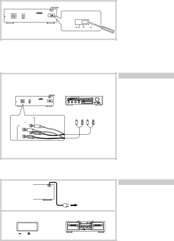
Setting the Voltage Selector (Worldwide Model Only)
Models without a voltage selector can only be used in areas where the power supply is the same as that of the cassette deck.
|
|
|
1. Determine the proper voltage for your |
|
|
|
area: 220-230 V or 120 V. |
|
VOLTAGE SELECTOR |
2. If the preset voltage does not conform |
|
C A U T I O N |
to your area, insert a screwdriver into |
||
220V-230V |
120V |
|
the groove in the switch. Slide the |
|
|
|
switch all the way to the right (120 V) |
|
220V-230V |
120V |
or to the left (220-230 V), whichever is |
|
appropriate. |
||
|
|
|
|
System Connections
•Do not plug in the AC power cord until all other connections have been made.
•On each pair of input or output jacks, the lower jack (marked R) corresponds to the right channel, and the upper jack (marked L) to the left channel. Refer to the amplifier’s instruction manual for further information on connections.
|
C A U T I O N |
|
|
|
|
|
|
|
|
• |
- |
• |
- |
• |
|
|
|
|
|
|
|
|
|
TAPE |
|
|
|
|
|
|
|
(REC) |
|
|
(PLAY) |
|
OUT |
|
|
|
L |
R |
L |
R |
|
|
|
|
|
|
|
|
|
IN |
LINE |
|
|
|
|
|
|
|
(PLAY) |
|
|
|
|
|
|
|
|
LINE |
|
|
|
|
|
|
|
|
|
|
|
|
|
|
|
|
|
(REC) |
|
|
|
|
|
|
|
|
L |
|
|
|
|
|
|
|
|
R |
|
|
|
|
|
|
|
|
Connecting to an amplifier
Connect the tape deck LINE IN jacks to the TAPE REC jacks on the rear panel of the amplifier and the tape deck LINE OUT jacks to the amplifier TAPE PLAY jacks. Refer to the amplifier’s instruction manual for further information on connections.
Power Connections
1 |
Switching power on |
|
1. Plug the AC power cord into a |
||
|
||
|
wall outlet. |
|
|
2. Press the POWER button. |
|
|
The display will light. |
|
|
To a wall outlet |
|
2 |
POWER |
|
|
ON OFF |
5
To Play a Tape
•Check once again that all connections have been completed exactly as indicated in the connections diagram and then plug in the AC power cord.
•After turning the power on, the display illuminates and the g PAUSE indicator flashes (about 5 seconds). While the indicator is flashing, no operation can be performed.
•This deck holds two cassettes at once. Both Deck A and Deck B are capable of auto-reverse playback.
•Tapes can be played back using either Deck A or Deck B. Follow the procedure on Deck A or B. (Deck A is pictured.)
|
|
2 |
|
|
|
1 |
5 |
|
|
|
|
|
|
|
|
|
|
|
|
|
|
|
|||||||
|
|
|
|
|
|
|
|
|
|
|
|
|
|
|
|
|
|
|
|
|
|
|
|
|
|
|
|
|
|
|
|
|
|
|
|
|
|
|
|
|
|
|
|
|
|
|
|
|
|
|
|
|
|
|
|
|
|
|
|
|
|
|
|
|
|
|
|
|
|
|
|
|
|
|
|
|
|
|
|
|
|
|
|
|
|
|
|
|
|
|
|
|
|
|
|
|
|
|
|
|
|
|
|
|
|
|
|
|
|
|
|
|
|
|
|
|
|
|
|
|
|
|
|
|
|
|
|
|
|
|
|
|
|
|
|
|
|
|
|
|
|
|
|
|
|
|
|
|
|
|
|
|
|
|
|
|
|
|
|
|
|
|
|
|
|
|
|
|
|
|
|
|
|
|
|
|
|
|
|
|
|
|
|
|
|
|
|
|
|
|
|
|
|
|
|
|
|
|
|
|
|
|
|
|
|
|
|
|
|
|
|
|
|
|
|
|
|
|
|
|
|
|
|
|
|
|
|
|
|
|
|
|
|
|
|
|
|
|
|
|
|
|
|
|
|
|
|
|
|
|
|
|
|
|
|
|
|
|
|
|
|
|
|
|
|
|
|
|
|
|
|
|
|
|
|
|
|
|
|
|
|
|
|
|
|
|
|
|
|
|
|
|
|
|
|
|
|
|
|
d,f(DECK A) 3 4 d,f(DECK B)
1 EJECT
2
3 DOLBY NR DOLBY NR
OFF 
 B
B 
 C
C
4
REVERSE MODE
5
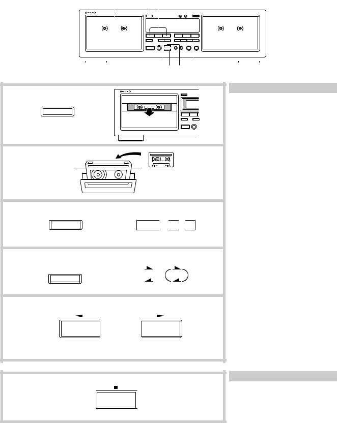
Listening to a tape
1.Press the EJECT button to open the cassette holder.
2.Insert a cassette.
•The side of the cassette with the exposed tape should be facing downward.
3.Set the Dolby NR by pressing the DOLBY NR button repeatedly until the proper Dolby NR indicator (OFF, B or C) turns on.
•Select the same noise reduction system that was used when the cassette was recorded. For instance, tapes recorded using Dolby B NR should be played back with Dolby B NR.
4.Set the Reverse Mode by pressing the REVERSE MODE button repeatedly until the desired mode is displayed.
( v ) one side: Only one side of the tape is played back.
( b ) repeat: Both sides of the tape are played back repeatedly eight times or until the e button is pressed.
5.Start playback.
•Press the a or s button depending on which side of the cassette you wish to listen to.
s : Playback starts from the front side.
a : Playback starts from the reverse side.
•The auto-stop mechanism will automatically stop the tape (depending on the tape transport mode) if a tape is played through to the end.
Stopping playback
Press the e button.
6
Loading...