


 Loading...
Onkyo SKM-550S, SKF-550F, SKC-550C, HT-R550, SKB-550 User Manual
...7.1ch Home Theater System
HT-SR800
AV Receiver (HT-R550)
Front Speakers (SKF-550F)
Center Speaker (SKC-550C)
Surround Speakers (SKM-550S)
Surround Back Speakers (SKB-550)
Powered Subwoofer (SKW-550)
Instruction Manual
Thank you for purchasing an Onkyo 7.1ch Home Theater System. Please read this manual thoroughly before making connections and plugging in the unit. Following the instructions in this manual will enable you to obtain optimum performance and listening enjoyment from your new 7.1ch Home Theater System.
Please retain this manual for future reference.
Contents
Introduction ..................................... |
2 |
Connection .................................... |
19 |
Turning On & First Time Setup..... 36
Basic Operation |
|
Playing your AV components ....... |
42 |
Listening to the Radio .................. |
44 |
Enjoying the Listening Modes ..... 48
Advanced Operation ..................... |
55 |
Troubleshooting ............................ |
65 |
En
WARNING:
TO REDUCE THE RISK OF FIRE OR ELECTRIC SHOCK, DO NOT EXPOSE THIS APPARATUS TO RAIN OR MOISTURE.
CAUTION:
TO REDUCE THE RISK OF ELECTRIC SHOCK, DO NOT REMOVE COVER (OR BACK). NO USER-SERVICEABLE PARTS INSIDE. REFER SERVICING TO QUALIFIED SERVICE PERSONNEL.
WARNING |
|
AVIS |
RISK OF ELECTRIC SHOCK |
|
RISQUE DE CHOC ELECTRIQUE |
DO NOT OPEN |
|
NE PAS OUVRIR |
|
|
|
The lightning flash with arrowhead symbol, within an equilateral triangle, is intended to alert the user to the presence of uninsulated “dangerous voltage” within the product’s enclosure that may be of sufficient
magnitude to constitute a risk of electric shock to persons.
The exclamation point within an equilateral triangle is intended to alert the user to the presence of important operating and maintenance (servicing) instructions in the literature accompanying the appliance.
Important Safety Instructions
1.Read these instructions.
2.Keep these instructions.
3.Heed all warnings.
4.Follow all instructions.
5.Do not use this apparatus near water.
6.Clean only with dry cloth.
7.Do not block any ventilation openings. Install in accordance with the manufacturer’s instructions.
8.Do not install near any heat sources such as radiators, heat registers, stoves, or other apparatus (including amplifiers) that produce heat.
9.Do not defeat the safety purpose of the polarized or grounding-type plug. A polarized plug has two blades with one wider than the other. A grounding type plug has two blades and a third grounding prong. The wide blade or the third prong are provided for your safety. If the provided plug does not fit into your outlet, consult an electrician for replacement of the obsolete outlet.
10.Protect the power cord from being walked on or pinched particularly at plugs, convenience receptacles, and the point where they exit from the apparatus.
11.Only use attachments/accessories specified by the manufacturer.
12. Use only with the cart, stand, tripod, bracket, or table specified by the manufacturer, or sold with the apparatus. When a cart is used, use caution when moving the cart/ apparatus combination to avoid injury from tip-over.
13.Unplug this apparatus during lightning storms or when unused for long periods of time.
14.Refer all servicing to qualified service personnel. Servicing is required when the apparatus has been damaged in any way, such as power-supply cord or plug is damaged, liquid has been spilled or objects have fallen into the apparatus, the apparatus has been exposed to rain or moisture, does not operate normally, or has been dropped.
15.Damage Requiring Service
Unplug the apparatus from the wall outlet and refer servicing to qualified service personnel under the following conditions:
A.When the power-supply cord or plug is damaged,
B.If liquid has been spilled, or objects have fallen into the apparatus,
C.If the apparatus has been exposed to rain or water,
D.If the apparatus does not operate normally by following the operating instructions. Adjust only those controls that are covered by the operating instructions as an improper adjustment of other controls may result in damage and will often require extensive work by a qualified technician to restore the apparatus to its normal operation,
E.If the apparatus has been dropped or damaged in any way, and
F.When the apparatus exhibits a distinct change in performance this indicates a need for service.
16.Object and Liquid Entry
Never push objects of any kind into the apparatus through openings as they may touch dangerous voltage points or short-out parts that could result in a fire or electric shock.
The apparatus shall not be exposed to dripping or splashing and no objects filled with liquids, such as vases shall be placed on the apparatus.
Don’t put candles or other burning objects on top of this unit.
17.Batteries
Always consider the environmental issues and follow local regulations when disposing of batteries.
18.If you install the apparatus in a built-in installation, such as a bookcase or rack, ensure that there is adequate ventilation.
Leave 20 cm (8") of free space at the top and sides and 10 cm (4") at the rear. The rear edge of the shelf or board above the apparatus shall be set 10 cm (4") away from the rear panel or wall, creating a flue-like gap for warm air to escape.
2

Precautions
1.Recording Copyright—Unless it’s for personal use only, recording copyrighted material is illegal without the permission of the copyright holder.
2.AC Fuse—The AC fuse inside the unit is not userserviceable. If you cannot turn on the unit, contact your Onkyo dealer.
3.Care—Occasionally you should dust the unit all over with a soft cloth. For stubborn stains, use a soft cloth dampened with a weak solution of mild detergent and water. Dry the unit immediately afterwards with a clean cloth. Don’t use abrasive cloths, thinners, alcohol, or other chemical solvents, because they may damage the finish or remove the panel lettering.
4.Power WARNING
BEFORE PLUGGING IN THE UNIT FOR THE FIRST TIME, READ THE FOLLOWING SECTION CAREFULLY.
AC outlet voltages vary from country to country. Make sure that the voltage in your area meets the voltage requirements printed on the unit’s rear panel (e.g., AC 230–240 V, 50 Hz or AC 120 V, 60 Hz).
The power cord plug is used to disconnect this unit from the AC power source. Make sure that the plug is readily operable (easily accessible) at all times.
Pressing the [STANDBY/ON] button to select Standby mode does not fully shutdown the unit. If you do not intend to use the unit for an extended period, remove the power cord from the AC outlet.
5.Never Touch this Unit with Wet Hands—Never handle this unit or its power cord while your hands are wet or damp. If water or any other liquid gets inside this unit, have it checked by your Onkyo dealer.
6.Handling Notes
•If you need to transport this unit, use the original packaging to pack it how it was when you originally bought it.
•Do not leave rubber or plastic items on this unit for a long time, because they may leave marks on the case.
•This unit’s top and rear panels may get warm after prolonged use. This is normal.
•If you do not use this unit for a long time, it may not work properly the next time you turn it on, so be sure to use it occasionally.
For U.S. models
FCC Information for User
CAUTION:
The user changes or modifications not expressly approved by the party responsible for compliance could void the user’s authority to operate the equipment.
NOTE:
This equipment has been tested and found to comply with the limits for a Class B digital device, pursuant to Part 15 of the FCC Rules. These limits are designed to provide reasonable protection against harmful interference in a residential installation.
This equipment generates, uses and can radiate radio frequency energy and, if not installed and used in accordance with the instructions, may cause harmful interference to radio communications. However, there is no guarantee that interference will not occur in a particular installation. If this equipment does cause harmful interference to radio or television reception, which can be determined by turning the equipment off and on, the user is encouraged to try to correct the interference by one or more of the following measures:
•Reorient or relocate the receiving antenna.
•Increase the separation between the equipment and receiver.
•Connect the equipment into an outlet on a circuit different from that to which the receiver is connected.
•Consult the dealer or an experienced radio/TV technician for help.
For Canadian Models
NOTE: THIS CLASS B DIGITAL APPARATUS COMPLIES WITH CANADIAN ICES-003.
For models having a power cord with a polarized plug: CAUTION: TO PREVENT ELECTRIC SHOCK, MATCH WIDE BLADE OF PLUG TO WIDE SLOT, FULLY INSERT.
Modèle pour les Canadien
REMARQUE: CET APPAREIL NUMÉRIQUE DE LA CLASSE B EST CONFORME À LA NORME NMB-003 DU CANADA.
Sur les modèles dont la fiche est polarisée: ATTENTION: POUR ÉVITER LES CHOCS ÉLECTRIQUES, INTRODUIRE LA LAME LA PLUS LARGE DE LA FICHE DANS LA BORNE CORRESPONDANTE DE LA PRISE ET POUSSER JUSQU’AU FOND.
3

Speaker Precautions
Placement
•The speaker cabinets are made out of wood and are therefore sensitive to extreme temperatures and humidity, do not put them in locations subject to direct sunlight or in humid places, such as near an air conditioner, humidifier, bathroom, or kitchen.
•Do not put water or other liquids close to the speakers. If liquid is spilled over the speakers, the drive units may be damaged.
•Speakers should only be placed on sturdy, flat surfaces that are free from vibration. Putting them on uneven or unstable surfaces, where they may fall and cause damage, will affect the sound quality.
•Subwoofer is designed to be used in the upright vertical position only. Do not use it in the horizontal or tilted position.
•If the unit is used near a turntable, CD player or DVD player, howling or slipping of sound may occur. To prevent this, move the unit away from the turntable, CD player or DVD player otherwise lower the unit’s output level.
Using Close to a TV or Computer
TVs and computer monitors are magnetically sensitive devices and as such are likely to suffer discoloration or picture distortion when conventional speakers are placed nearby. To prevent this, the SKF-550F and SKC-550C feature internal magnetic shielding. In some situations, however, discoloration may still be an issue, in which case you should turn off your TV or monitor, wait 15 to 30 minutes, and then turn it back on again. This normally activates the degaussing function, which neutralizes the magnetic field, thereby removing any discoloration effects. If discoloration problems persist, try moving the speakers away from your TV or monitor. Note that discoloration can also be caused by a magnet or demagnetizing tool that’s too close to your TV or monitor.
Input Signal Warning
The speakers can handle the specified input power when used for normal music reproduction. If any of the following signals are fed to them, even if the input power is within the specified rating, excessive current may flow in the speaker coils, causing burning or wire breakage:
1.Interstation noise from an untuned FM radio.
2.Sound from fast-forwarding a cassette tape.
3.High-pitched sounds generated by an oscillator, electronic musical instrument, and so on.
4.Amplifier oscillation.
5.Special test tones from audio test CDs and so on.
6.Thumps and clicks caused by connecting or disconnecting audio cables (Always turn off your amplifier before connecting or disconnecting cables.)
7.Microphone feedback.
4
Enjoying Home Theater
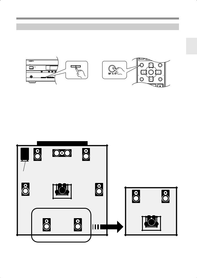
Speaker Sets A and B
You can use two sets of speakers with the AV receiver: speaker set A and speaker set B.
Speaker set A (included speakers) should be used in your main listening room for up to 7.1-channel playback.
*While speaker set B is on, speaker set A is reduced to 5.1-channel playback.
Speaker set B (not included) can be used in another room and offers 2-channel stereo playback.
*Only analog input sources are output by speaker set B.
|
|
|
|
|
|
|
|
|
|
|
|
|
|
|
MASTER VOLUME |
STANDBY/ON |
|
|
|
|
|
|
|
|
A |
SPEAKERSTUNING |
BPRESET |
|
|
||
STANDBY |
|
|
|
|
|
|
|
|
|
|
|
|
|
|
|
|
|
|
|
|
|
|
|
|
|
|
|
|
|
|
or |
MULTI CH |
|
DVD |
VCR/DVR |
CBL/SAT |
AUX |
TAPE |
TUNER |
C D |
|
SETUP |
ENTER |
RETURN |
|
|
|
|
|
|
|
|
|
|
|
|
|
|
|
|
|
AUX INPUT |
|
PHONES |
|
|
|
|
|
|
|
|
|
|
|
SETUP MIC |
VIDEO |
L AUDIO |
R |
A |
SPEAKERS |
B |
TONE |
|
STEREO |
LISTENING MODE |
DISPLAY DIGITAL INPUT |
DIMMER |
MEMORY TUNING MODE |
|
|
|
|
||
SP A / B |
MUTING |
|
ENTER |
PLAYLIST/CAT |
PLAYLIST/CAT |
Speaker set A |
Speaker set B |
|
Indicator |
|
Output |
|||
|
|
|
|
|
|
|
|
|
|
On |
|
|
|
|
|
|
Set A: 5.1 channels |
On |
|
A |
|
B |
|
|
Set B: 2 channels |
|
|
|
|
|
|
|
|
||
|
Off |
|
|
|
|
|
|
Set A: 7.1 channels |
|
|
A |
|
|
|
|
||
Off |
On |
|
|
|
B |
|
|
Set B: 2 channels |
|
|
|
|
|
|
|
|
|
Off |
|
|
|
|
|
|
No sound |
|
|
|
|
|
|
|
|
||
|
|
|
|
|
|
|
|
|
Main Room (speaker set A, the supplied speakers) |
|
Center speaker |
|
Front left |
Front right |
speaker |
speaker |
Subwoofer |
|
Surround |
Surround |
left |
right |
speaker |
speaker |
Surround back |
Surround back |
left speaker |
right speaker |
*While speaker set B is on, the surround back speakers output no sound.
Sub Room (speaker set B)
*Digital input sources are not output by speaker set B. Connect your source component with an analog connection.
5
Package Contents
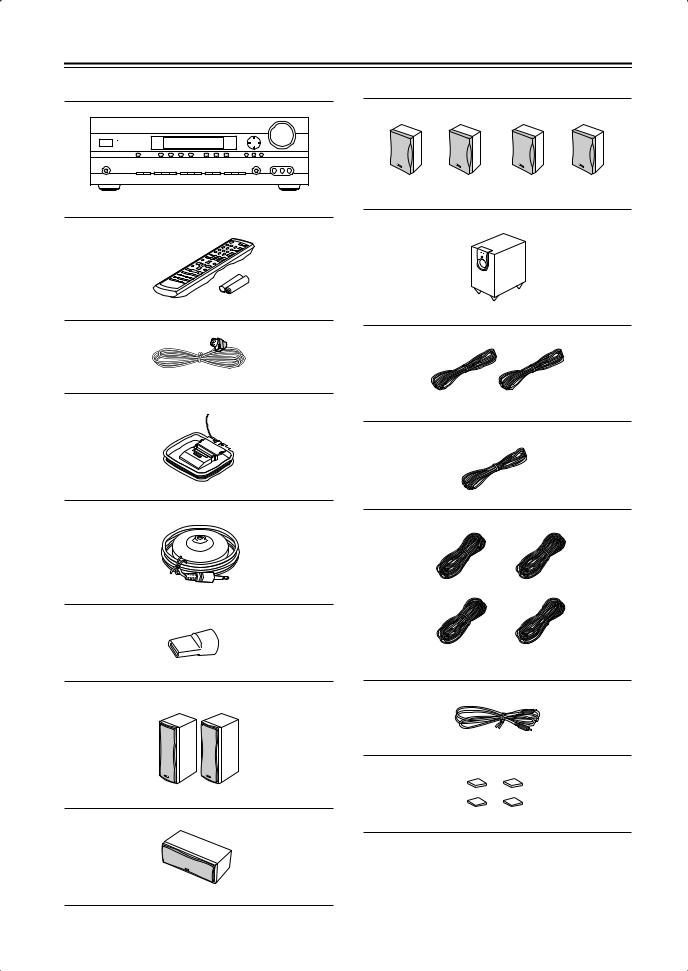
Make sure you have the following items:
AV receiver (HT-R550)
Remote controller and two batteries (AA/R6)
Indoor FM antenna
AM loop antenna
Speaker setup microphone
Speaker terminal tool
Front speakers (SKF-550F)
Center speaker (SKC-550C)
Surround and Surround back speakers (SKM-550S/SKB-550)
Subwoofer (SKW-550)
(Red) (White)
Speaker cable for front speakers 11 ft. (3.5 m)
(Green)
Speaker cable for center speaker 10 ft. (3 m)
(Blue) (Gray)
(Brown) (Tan)
Speaker cables for surround speakers 30 ft. (9 m)
RCA cable for subwoofer connection 10 ft. (3 m)
4 floor pads for the subwoofer
*In catalogs and on packaging, the letter at the end of the product name indicates the color. Specifications and operation are the same regardless of color.
6
Features
Amplifier
•7-channel amplifier
•110 watts per channel rms into 8 ohms, 2 channels driven at 1 kHz, less than 0.9% total harmonic distortion (FTC rating)
•WRAT (Wide Range Amplifier Technology)
•Optimum Gain Volume Circuitry
•Audyssey 2EQ/HTIB room correction*1
Processing
•Dolby*2 Digital EX and Dolby Pro Logic IIx
•DTS, DTS-ES Matrix/Discrete, DTS Neo:6, and DTS 96/24*3
•Neural Surround*4 (North American models only)
•Theater-Dimensional*5 virtual surround sound
•Linear PCM 192 kHz/24-bit D/A converters on all channels
•Pure Audio listening mode (not North American model)
•Powerful and highly accurate 32-bit DSP processing
Audio/Video
•2 HDMI*6 inputs, 1 output
•Adjustable crossover (40, 50, 60, 80, 100, 120, 150, 200 Hz)
•HDTV-capable component video (3 inputs, 1 output)
•3 S-Video inputs, 2 outputs
•4 assignable digital inputs (2 optical, 2 coaxial)
•Subwoofer pre out
•Color-coded 7.1 multichannel input for use with Super Audio CD and DVD-Audio
•A/B speaker drive
•Color-coded speaker terminal posts
Tuner
•XM*7 Satellite Radio (North American models only)
*XM Passport System required; sold separately.
•SIRIUS*8 Satellite Radio (North American models only)
•40 radio presets
•AM/FM auto tuning
Remote Controller
• Preprogrammed for use with other AV components
Speaker
•Color-coded speaker terminals and speaker cables
•Subwoofer Auto standby function
•Magnetically shielded front and center speakers
*1
Manufactured under license from Audyssey Laboratories. U.S. and foreign patents pending. Audyssey 2EQ/HTIB is a trademark of Audyssey Laboratories.
*2
Manufactured under license from Dolby Laboratories. “Dolby”, “Pro Logic” and the double-D symbol are registered trademarks of Dolby Laboratories.
*3
“DTS” and “DTS-ES | Neo: 6” are registered trademarks of DTS, Inc. “96/24” is a trademark of DTS, Inc.
*4
Neural Surround name and related logos are trademarks owned by Neural Audio Corporation.
*5
Theater-Dimensional is a trademark of Onkyo Corporation.
*6
HDMI, the HDMI logo and High Definition Multimedia Interface are trademarks or registered trademarks of HDMI Licensing, LLC. This unit incorporates HDMI technology.
*7
XM Ready® is a registered trademark of XM Satellite Radio Inc. All rights reserved.
*8
©2005 SIRIUS Satellite Radio Inc. “SIRIUS,” the SIRIUS dog logo, channel names and logos are trademarks of SIRIUS Satellite Radio Inc. Available only in the contiguous United States (excluding Alaska and Hawaii) and Canada.
7

Getting Started in Five Easy Steps
1. Hookup
Connect the speakers and your AV components to the AV receiver.
page 19
|
HDMI |
SIRIUS |
XM |
IN 2 |
IN 1 |
ANTENNA |
|
DIGITAL IN |
|
|
L |
|
|
|
CBL/SAT |
VCR/DVR |
DVD |
MONITOR |
|
|
|
|
|
OUT |
V |
|
|||
|
|
|
V |
|
|
|
R |
|
|
|
|
|
|
|
|
S |
|
|
|
|
S |
|
|
|
|
|
|
|
|
|
|
|
|
SURROUND BACK |
SURROUND |
COMPONENT VIDEO |
|
|
|
|
|
SPEAKERS |
SPEAKERS |
|
L |
|
L |
L |
|
|
|
L |
|
R |
|
R |
R |
|
|
|
R |
|
CD |
TAPE |
|
CBL/SAT |
VCR/DVR |
|
DVD |
|
|
L |
|
R |
|
FRONT |
CENTER |
SPEAKERS A |
SPEAKER |
L |
|
R |
|
FRONT |
|
SPEAKERS B |
|
2. Turning On
With the hookup complete, you’re ready to switch on.
page 36
3. First Time Setup
A few simple settings to get the very best from your system.
page 37 |
HDMI Video |
|
Setup |
||
|
||
|
Automatic |
|
|
Speaker Setup |
Digital Input
Input Display
4. Playing Your AV Components
Enjoying movies and music.
page 42
5. Using the Listening Modes
Time to really enjoy your home theater system!
page 48
8
Contents
Introduction |
|
|
Important Safety Instructions .................... |
2 |
|
Precautions ................................................. |
|
3 |
Speaker Precautions .................................. |
|
4 |
Enjoying Home Theater.............................. |
5 |
|
Speaker Sets A and B ................................... |
|
5 |
Package Contents....................................... |
|
6 |
Features ....................................................... |
|
7 |
Getting to Know the AV Receiver............ |
10 |
|
Remote Controller..................................... |
|
13 |
Speakers .................................................... |
|
18 |
Connection |
|
|
Connecting Your Speakers ...................... |
19 |
|
Connecting Antennas............................... |
|
22 |
Connecting Your Components ................ |
24 |
|
About AV Connections ................................ |
|
24 |
Connecting Audio and Video Signals |
|
|
to the AV Receiver .................................... |
|
25 |
Which Connections Should I Use?.............. |
25 |
|
TV or Projector .......................................... |
|
26 |
DVD player................................................. |
|
27 |
Components with HDMI |
.............................. |
29 |
VCR or DVD Recorder for Playback ........... |
30 |
|
VCR or DVD Recorder for Recording.......... |
31 |
|
Camcorder, Games Console, |
|
|
or Other Device......................................... |
|
31 |
Satellite, Cable, Set-top box, |
|
|
or Other Video Source |
.............................. |
32 |
CD Player or Turntable................................ |
|
33 |
RI Dock........................................................ |
|
34 |
Cassette, CDR, MiniDisc, |
|
|
or DAT Recorder....................................... |
|
34 |
Connecting Onkyo |
Components.......... |
35 |
Connecting the Power Cord ........................ |
35 |
|
Turning On & First Time Setup |
|
|
Turning On the AV Receiver .................... |
36 |
|
First Time Setup........................................ |
|
37 |
Automatic Speaker Setup |
|
|
(Audyssey 2EQ/HTIB)............................... |
|
37 |
HDMI Video Setup....................................... |
|
40 |
Digital Audio Input Setup............................. |
41 |
|
Changing the Input Display ......................... |
41 |
|
Basic Operation |
|
Playing Your AV Components ................ |
42 |
Basic AV Receiver Operation ..................... |
42 |
Using the Multichannel DVD Input.............. |
43 |
Displaying Source Information.................... |
43 |
Listening to the Radio.............................. |
44 |
Listening to AM/FM Stations....................... |
44 |
Presetting AM/FM Stations ......................... |
45 |
Common Functions.................................. |
46 |
Setting the Display Brightness.................... |
46 |
Adjusting the Bass and Treble.................... |
46 |
Muting the AV Receiver .............................. |
46 |
Using the Sleep Timer ................................ |
47 |
Using Headphones ..................................... |
47 |
Adjusting Speaker Levels ........................... |
47 |
Enjoying the Listening Modes |
|
Using the Listening Modes...................... |
48 |
Selecting Listening Modes.......................... |
48 |
About the Listening Modes ......................... |
50 |
Using the Late Night Function |
|
(Dolby Digital only) ................................... |
52 |
Using the CinemaFILTER........................... |
52 |
Using the Audio Adjust Settings ................. |
52 |
Advanced Operation |
|
Recording.................................................. |
55 |
Advanced Setup ....................................... |
56 |
Advanced Speaker Settings ....................... |
56 |
Digital Input Signal Formats ....................... |
61 |
Correcting Sound and Picture Sync ........... |
61 |
Controlling Other Components............... |
62 |
Entering Remote Control Codes................. |
62 |
Remote Control Codes for Onkyo |
|
Components Connected via .............. |
63 |
Resetting REMOTE MODE Buttons ........... |
63 |
Resetting the Remote Controller ................ |
63 |
Troubleshooting ....................................... |
65 |
If you can’t resolve an issue, try resetting the AV receiver by holding down the [VCR/DVR] button and pressing the [STANDBY/ON] button.
Specifications ........................................... |
69 |
9
Getting to Know the AV Receiver
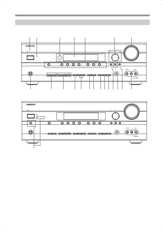
Front Panel
North American Model
1 |
2 |
|
|
3 |
|
4 |
5 |
|
|
|
|
6 |
|
7 |
|
|
|
|
|
|
|
|
|
|
|
|
|
|
|
|
|
|
MASTER VOLUME |
STANDBY/ON |
|
|
|
|
|
|
|
|
|
|
TUNING |
PRESET |
|
|
||
|
STANDBY |
|
|
|
|
|
|
|
|
|
|
|
|
|
|
|
|
MULTI CH |
|
DVD |
VCR/DVR |
CBL/SAT |
AUX |
TAPE |
TUNER |
C D |
SETUP |
ENTER |
RETURN |
|
|
||
|
|
|
|
|
|
|
|
|
|
|
|
|
|
|
AUX INPUT |
|
PHONES |
|
|
|
|
|
|
|
|
|
|
|
|
SETUP MIC |
VIDEO |
L AUDIO |
R |
|
A |
SPEAKERS |
B |
TONE |
|
STEREO |
LISTENING MODE |
DISPLAY DIGITAL INPUT |
DIMMER |
MEMORY TUNING MODE |
|
|
|
|
|
|
|
|
|
|
|
|
|
|
|
|
|
CLEAR |
|
|
|
|
|
8 |
|
9 J K L MN OP Q R S T U |
|
|||||||||||||
Other Models
|
|
|
|
|
|
|
|
|
|
|
|
MASTER VOLUME |
STANDBY/ON |
|
|
|
|
|
|
|
|
TUNING PRESET |
|
||
|
STANDBY |
|
|
|
|
|
|
|
|
|
|
|
|
PURE AUDIO |
|
|
|
|
|
|
|
|
|
|
|
PURE AUDIO |
MULTI CH |
DVD |
VCR/DVR |
CBL/SAT |
AUX |
TAPE |
TUNER |
C D |
SETUP |
ENTER |
RETURN |
|
|
|
|
|
|
|
|
|
|
|
|
|
AUX INPUT |
PHONES |
|
|
|
|
|
|
|
|
|
SETUP MIC |
VIDEO |
L AUDIO R |
|
A SPEAKERS B |
TONE |
|
STEREO |
LISTENING MODE |
DISPLAY DIGITAL INPUT |
DIMMER MEMORY TUNING MODE |
|
|
|
||
|
|
|
|
|
|
|
|
|
CLEAR |
|
|
|
V |
|
|
|
|
|
|
|
|
|
|
|
|
For detailed information, see the pages in parentheses. |
|
F Arrow/TUNING/PRESET and ENTER buttons |
||||||||||
ASTANDBY/ON button (36)
Sets the AV receiver to On or Standby.
BSTANDBY indicator (36)
Lights up when the AV receiver is on Standby and flashes while a signal is being received from the remote controller.
CRemote-control sensor (13)
Receives control signals from the remote controller.
DDisplay
See “Display” on page 11.
EInput selector buttons (42)
Select the input sources.
The [MULTI CH] button selects the multichannel DVD input.
When the tuner is selected, the TUNING [ ] [
] [ ] buttons are used for radio tuning, and the PRESET [
 ] [
] [ ] buttons are used to select radio presets (see page 45). With the setup menus, they work as arrow buttons and are used to select and set items. The ENTER button is also used with the setup menus.
GMASTER VOLUME control (42)
Sets the volume of the AV receiver to MIN, 1 through 79, or MAX.
HPHONES jack (47)
This 1/4-inch phone jack is for connecting a standard pair of stereo headphones for private listening.
ISPEAKERS A and B buttons (5, 42)
Turn speaker sets A and B on or off.
10
Getting to Know the AV Receiver—Continued
JTONE, [–], and [+] buttons (46)
Used to adjust the bass and treble.
KSTEREO button (48)
Selects the Stereo listening mode.
LLISTENING MODE [ ]/[
]/[ ] buttons (48)
Select the listening modes.
MDISPLAY button (43)
Displays various information about the currently selected input source.
NDIGITAL INPUT button (41, 61)
Used to assign the digital inputs and to specify the format of digital input signals.
ODIMMER button (46)
Adjusts the display brightness.
PMEMORY button (45)
Used when storing or deleting radio presets.
Display
1 2 |
3 |
|
|
|
|
QTUNING MODE button (44)
Selects the Auto or Manual tuning mode for AM and FM radio.
RSETUP button
Used to access the setup menus.
SSETUP MIC (38)
The automatic speaker setup microphone connects here.
TRETURN button
Selects the previously displayed setup menu.
UAUX INPUT (31, 55)
Used to connect a camcorder, games console, and so on. There are jacks for composite video and analog audio.
VPURE AUDIO button and indicator (48)
The North American model doesn’t have this button and indicator.
Selects the Pure Audio listening mode. The indicator lights up when this mode is selected.
4 5
6 |
7 |
8 |
For detailed information, see the pages in parentheses.
1A and B speaker indicators (5, 42)
Indicator A lights up when speaker set A is on. Indicator B lights up when speaker set B is on.
2MUTING indicator (46)
Flashes while the AV receiver is muted.
3Input signal format indicators
Show the audio signal format of the current input source.
4Listening mode indicators (50)
Show the selected listening mode.
5Radio indicators
FM STEREO (44): Lights up when tuned to a stereo FM station.
AUTO (44): For AM and FM radio, lights up when Auto Tuning mode is selected, and disappears when Manual Tuning mode is selected.
TUNED (44): Lights up when tuned to a radio station.
6SLEEP indicator (47)
Lights up when the Sleep function has been set.
7Message area
Displays various information about the selected input source.
8Audyssey indicator (37)
Lights up during automatic speaker setup.
11

Getting to Know the AV Receiver—Continued
Rear Panel
78(North American model only)
1 |
2 |
3 |
4 56 |
|
9 |
|
|
|
|
|
|
|
|
|
|
|
HDMI |
SIRIUS |
XM |
IN 2 |
IN 1 |
OUT |
ASSIGNABLE |
ANTENNA |
|
|
|
|
AM |
FM 75 |
|
DIGITAL IN |
L |
L |
ASSIGNABLE |
|
|
|
|
|
|
|
|
|
|
|
|
|
|
COAX- |
|
|
|
|
|
|
|
|
|
|
|
|
|
|
IAL1 |
|
|
|
Y |
|
|
|
|
|
|
|
|
|
|
(DVD) |
|
|
|
|
|
|
|
|
MONITOR |
|
|
|
|
|
|
|
|
|
|
CBL/SAT |
VCR/DVR |
DVD |
|
|
|
|
|||
|
|
|
|
|
OUT |
V |
|
|
|
|
||||
2 |
|
|
|
CB/PB |
V |
|
|
|
|
R |
|
|
R |
|
(CBL/SAT) |
|
|
|
|
|
|
|
|
|
|
|
|
|
|
OPTICAL |
|
|
|
|
|
|
|
|
|
S |
|
|
|
|
1 |
|
|
|
CR/PR |
S |
|
|
|
|
|
|
|
|
|
(VCR/DVR) |
|
|
|
|
|
|
|
|
|
SURROUND BACK |
SURROUND |
FRONT |
CENTER |
|
|
|
|
|
|
|
|
|
|
|
|||||
|
CBL/SAT IN VCR/DVR IN |
DVD IN |
OUT |
|
IN |
OUT |
IN |
IN |
|
SPEAKERS |
SPEAKERS |
SPEAKERS A |
SPEAKER |
|
|
COMPONENT VIDEO |
|
|
|
|
|
|
|
|
|||||
2 |
|
|
|
|
|
|
|
|
|
|
|
|
||
IN |
OUT |
IN |
|
IN |
OUT |
IN |
FRONT |
SURROUND CENTER |
SURR BACK |
|
PRE OUT |
|
||
(CD) |
|
|
L |
|
||||||||||
|
|
|
|
|
|
|
|
|
|
|
|
|
|
|
|
|
|
|
|
|
|
|
|
|
|
|
|
SUB |
|
|
L |
|
|
L |
L |
|
|
|
|
|
L |
|
WOOFER |
|
|
R |
|
|
R |
|
|
|
|
|
|
|
|
R |
|
|
|
|
R |
|
|
|
|
|
R |
|
|
|
||
REMOTE |
|
|
|
|
|
|
|
|
|
SUB |
|
|
FRONT |
|
|
|
|
|
|
|
|
|
|
WOOFER |
|
|
|
||
CONTROL |
CD |
TAPE |
|
|
CBL/SAT |
VCR/DVR |
|
DVD |
|
|
SPEAKERS B |
|
||
|
|
|
|
|
|
|
|
|||||||
J K L M N O P
ADIGITAL IN OPTICAL 1, 2 and COAXIAL 1, 2
These optical and coaxial digital audio inputs are for connecting components with optical or coaxial digital audio outputs, such as CD and DVD players.
BHDMI IN 1, 2, and OUT
These jacks are for connecting HDMI-compatible components. Audio and video signals received by the HDMI IN jacks pass through to the HDMI OUT jack.
CCOMPONENT VIDEO
A DVD player, TV, or other component that supports component video can be connected here.
DAM ANTENNA
These push terminals are for connecting an AM antenna.
EFM ANTENNA
This jack is for connecting an FM antenna.
FMONITOR OUT
The S-Video or composite video output should be connected to a video input on your TV or projector.
GSIRIUS antenna (North American models only)
This jack is for connecting a SIRIUS Satellite Radio antenna (see the separate SIRIUS instructions).
HXM antenna (North American models only)
This jack is for connecting an XM Passport System, sold separately (see the separate XM instructions).
IFRONT SPEAKERS A, SURROUND SPEAKERS, CENTER SPEAKER, and SURROUND BACK SPEAKERS
These terminal posts are for connecting speaker set A.
J
 REMOTE CONTROL
This 
 Remote Interactive jack can be connected to the
 jack on another
 -capable Onkyo component. To use
 , you must make an analog audio connection (RCA) between the AV receiver and the other component, even if they are connected digitally.
KCD IN
This analog audio input is for connecting a CD player’s analog audio output.
LTAPE IN/OUT
This analog audio input and output are for connecting a recorder with an analog audio input and output, such as a cassette deck, MD recorder, etc.
MVCR/DVR IN/OUT and CBL/SAT IN
The VCR/DVR inputs and outputs can be used to connect a VCR or DVR (digital video recorder).
The CBL/SAT inputs can be used to connect a cable/satellite receiver, set-top box, etc.
NDVD IN
These jacks can be used to connect a DVD player with an analog multichannel audio output for SACD and DVD-Audio playback.
OSUBWOOFER PRE OUT
A powered subwoofer can be connected here.
PFRONT SPEAKERS B
These push terminals are for connecting speaker set B.
See pages 19–35 for hookup information.
12
Remote Controller
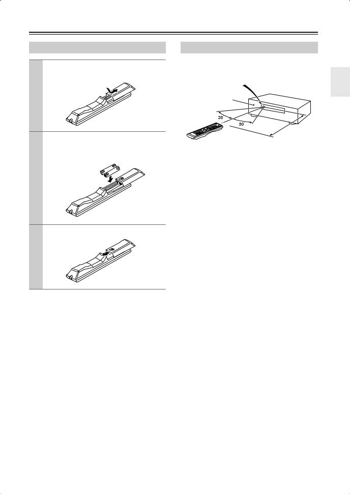
Installing the Batteries
1 To open the battery compartment, press the small hollow and slide open the cover.
2 Insert the two supplied batteries (AA/R6) in accordance with the polarity diagram inside the battery compartment.
3 Slide the cover shut.
Notes:
•If the remote controller doesn’t work reliably, try replacing the batteries.
•Don’t mix new and old batteries or different types of batteries.
•If you intend not to use the remote controller for a long time, remove the batteries to prevent damage from leakage or corrosion.
•Expired batteries should be removed as soon as possible to prevent damage from leakage or corrosion.
Aiming the Remote Controller
When using the remote controller, point it toward the AV receiver’s remote control sensor, as shown below.
Remote control sensor
AV receiver
STANDBY indicator
Approx. 16 ft. (5 m)
Notes:
•The remote controller may not work reliably if the AV receiver is subjected to bright light, such as direct sunlight or inverter-type fluorescent lights. Keep this in mind when installing.
•If another remote controller of the same type is used in the same room, or the AV receiver is installed close to equipment that uses infrared rays, the remote controller may not work reliably.
•Don’t put anything on top of the remote controller, such as a book or magazine, because a button may be pressed continuously, thereby draining the batteries.
•The remote controller may not work reliably if the AV receiver is installed in a rack behind colored glass doors. Keep this in mind when installing.
•The remote controller will not work if there’s an obstacle between it and the AV receiver’s remote control sensor.
13
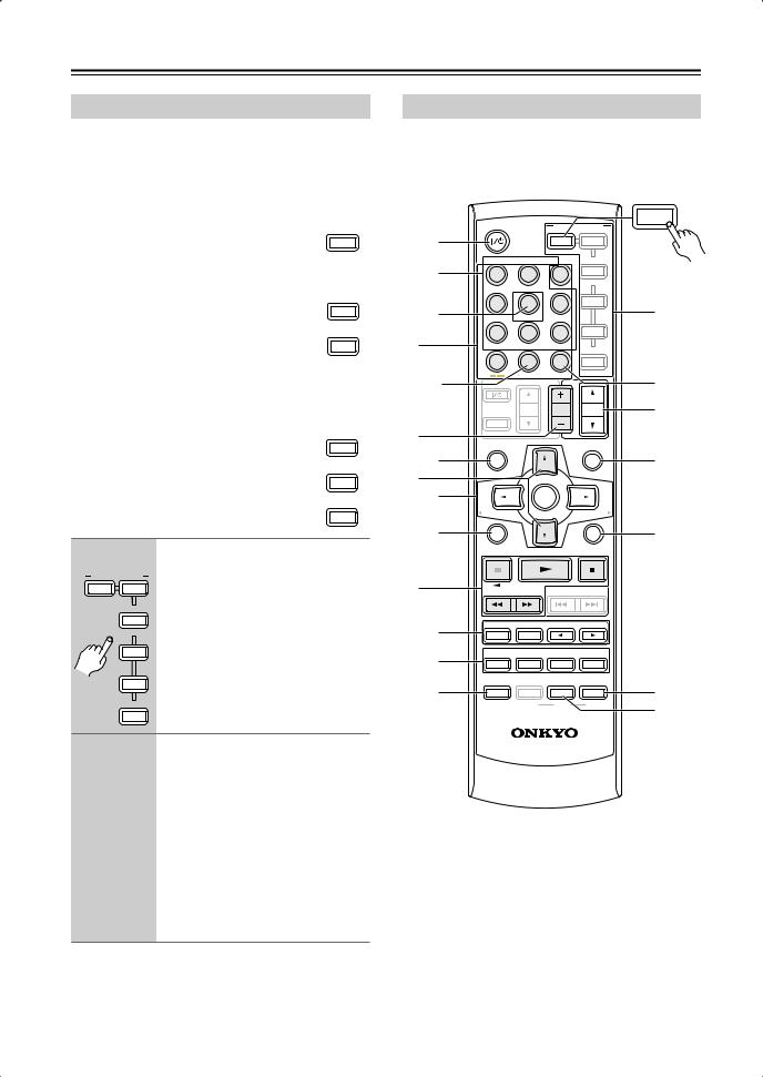
Remote Controller—Continued
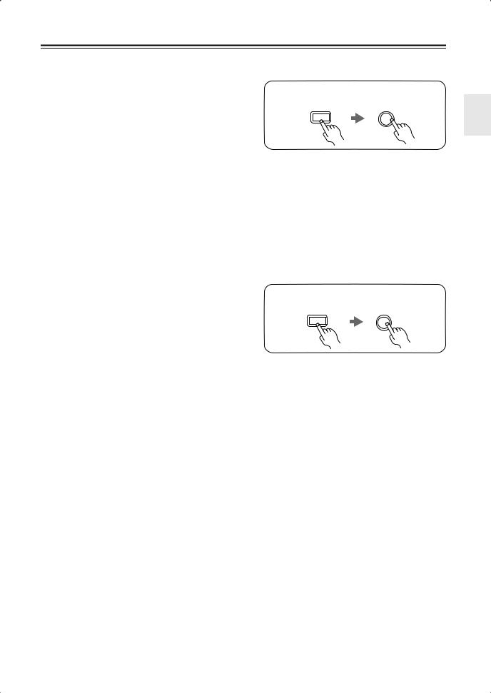
Using the Remote Controller
Including the AV receiver, the remote controller can be used to control up to seven different components. The remote controller has a specific operating mode for use with each type of component. Modes are selected by using the six REMOTE MODE buttons.
■ RECEIVER/TAPE Mode
In RECEIVER/TAPE mode, you can control the AV receiver and an Onkyo cassette recorder connected via 
 .
.
■ DVD and CD/MD/CDR/DOCK
Modes
With these modes, you can control a DVD
player and CD player, MD recorder, CDR, or RI dock. By entering the appropriate
remote control code, you can control Onkyo components or components made by other manufacturers (see page 62).
■ TV, VCR and SAT/CABLE Modes
With these modes, you can control a TV, |
TV |
|
|
||
VCR, and satellite or cable receiver. You |
VCR |
|
must enter the appropriate remote control |
||
|
||
code first (see page 62). |
CABLE |
|
|
SAT |
1 |
Press one of the REMOTE MODE |
|
|
REMOTE MODE |
buttons to select a mode. |
|
|
RECEIVER DVD |
|
TAPE/AMP |
|
M D/CDR |
|
CD |
|
DOCK |
|
TV |
|
VCR |
|
CABLE |
|
SAT |
|
2 |
Use the buttons supported by |
|
|
|
that mode to control the compo- |
|
nent. |
|
RECEIVER/TAPE mode: |
|
see right column |
DVD mode: see page 16
CD/MD/CDR/DOCK mode: see page 17
TV, VCR, SAT/CABLE modes: see page 64
Note:
Some of the remote controller operations described in this manual may not work as expected with other components.
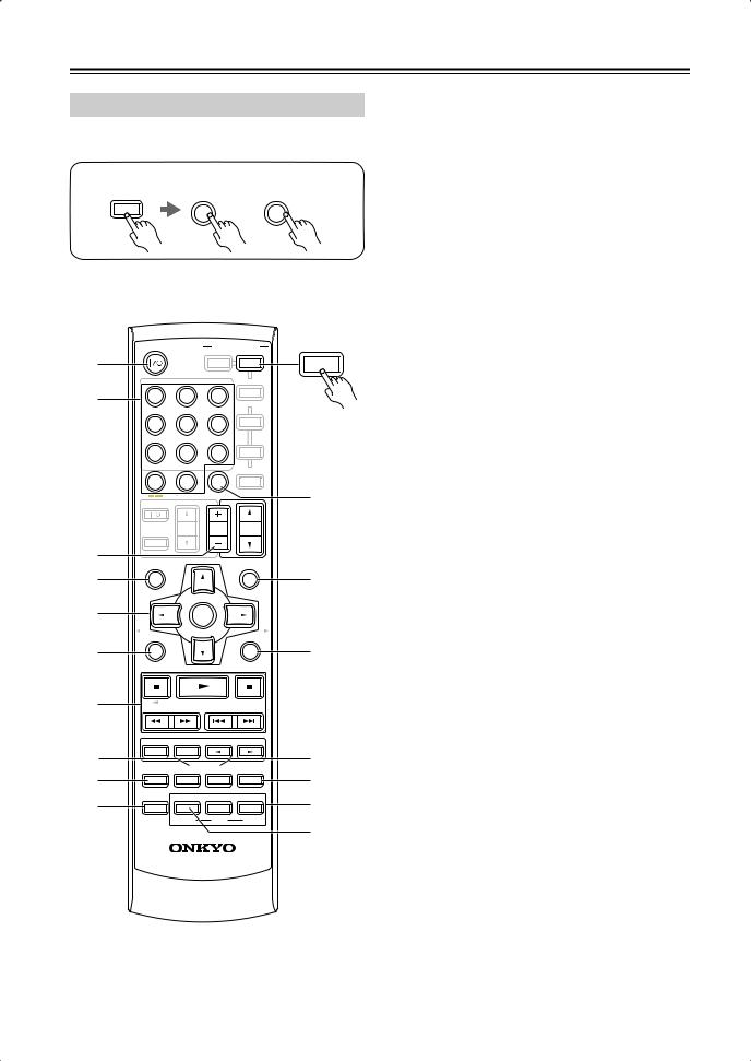
RECEIVER/TAPE Mode
RECEIVER/TAPE mode is used to control the AV receiver. It can also be used to control an Onkyo cassette recorder connected via 
 .
.
RECEIVER
|
STANDBY/ON |
|
REMOTE MODE |
|
|
1 |
|
|
RECEIVER |
DVD |
TAPE/AMP |
|
|
|
|||
|
|
|
|
||
|
|
TAPE/AMP |
|
||
|
INPUT SELECTOR |
M D/CDR |
|
||
2 |
1 |
2 |
3 |
CD |
|
DOCK |
|
||||
|
|
|
|
|
|
|
VCR/DVR |
CBL/SAT |
|
|
|
3 |
4 |
5 |
6 |
TV |
K |
AUX |
MULTI CH |
DVD |
|
||
1 |
7 |
8 |
9 |
VCR |
|
TAPE |
TUNER |
CD |
12 CABLE |
|
|
|
10 |
11 |
|
|
|
|
+10 |
0 |
CLR |
SAT |
|
|
D TUN |
ENT |
|
|
|
4 |
--/--- |
DIMMER |
SLEEP |
|
L |
|
|
|
|
||
|
TV |
VOL |
CH |
VOL |
M |
|
DISC |
||||
|
|
|
ALBUM |
|
|
|
INPUT |
|
|
|
|
2 |
GUIDE |
|
|
PREVIOUS |
|
|
TOP MENU |
|
|
MENU |
|
5 |
|
|
|
|
N |
3 |
SP A / B |
|
|
MUTING |
|
6 |
|
ENTER |
|
|
|
|
PLAYLIST/CAT |
|
PLAYLIST/CAT |
|
|
7 |
|
|
|
|
O |
SETUP |
RETURN |
4 |
|
8 |
|
LISTENING MODE |
|
|
|
STEREO |
SURROUND |
|
|
|
|
9 |
AUDIO |
SUBTITLE RANDOM |
REPEAT |
|
|
TEST TONE |
CH SEL |
LEVEL- |
LEVEL+ |
|
|
J |
|
PLAY MODE |
|
|
P |
DISPLAY |
|
L NIGHT |
CINE FLTR |
||
|
|
VCR |
DVD |
HDD |
Q |
|
|
|
|
|
|
|
|
RC-681M |
|
|
|
Buttons 1, 2, 3, and 4 are used when the TUNER or TAPE input is selected.
14
Remote Controller—Continued
For detailed information, see the pages in parentheses.
ASTANDBY/ON button (36)
Sets the AV receiver to On or Standby.
BINPUT SELECTOR buttons (42)
Used to select the input sources.
CMULTI CH button (43)
Selects the multichannel DVD input.
DDIMMER button (46)
Adjusts the display brightness.
ESP A/B button (5, 42)
Used to turn speaker sets A and B on or off.
FArrow [ ]/[
]/[ ]/[
]/[ ]/[
]/[ ] and ENTER buttons
Used to select and adjust settings.
GSETUP button
Used to access the setup menus.
HLISTENING MODE buttons (48)
Used to select the listening modes. These buttons work in all remote controller modes.
STEREO button
Selects the Stereo listening mode.
SURROUND button
Selects the Dolby and DTS listening modes and the Neural Surround listening mode (North American model only).
[ ]/[
]/[ ] buttons
Used to select the available listening modes.
ITEST TONE, CH SEL, LEVEL-, and LEVEL+ buttons (47, 59)
Used to adjust the level of each speaker.
JDISPLAY button (43)
Displays various information about the selected input source.
KREMOTE MODE buttons (14)
Used to select the remote controller modes. When a remote controller button is pressed, the REMOTE MODE button for the currently selected mode lights up.
LSLEEP button (47)
Used with the Sleep function.
MVOL [ ]/[
]/[ ] button (42)
Adjusts the volume of the AV receiver regardless of the currently selected remote controller mode.
NMUTING button (46)
Mutes or unmutes the AV receiver.
ORETURN button
Selects the previously displayed setup menu.
PCINE FLTR button (52)
Used with the CinemaFILTER function.
QL NIGHT button (52)
Used with the Late Night function.
■Buttons used when the TUNER input is selected
To select the Tuner (AM/FM) as the input source, press:
RECEIVER |
8 |
|
TUNER |
1Number, D TUN, and ENT buttons (45)
Used to select AM and FM radio stations directly.
2CH +/– button (45)
Used to select radio presets.
3Arrow [ ]/[
]/[ ] buttons
For AM and FM, the Up and Down [ ]/[
]/[ ] buttons are used for tuning.
■Buttons used when the TAPE input is selected
To select your Cassette deck as the input source, press:
RECEIVER |
7 |
|
TAPE |
4Playback buttons
On twin cassette decks, only deck B can be controlled.
Play [ ] button
Starts playback.
Stop [ ] button
Stops playback.
Reverse Play [ ] button
Starts reverse playback.
Rewind and FF [ ]/[
]/[ ] buttons
The Rewind [ ] button starts rewind. The FF [
 ] button starts fast forward.
15
Remote Controller—Continued
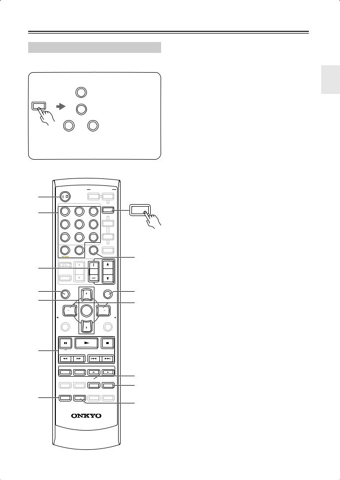
DVD Mode
By default, the remote controller is set to control an Onkyo DVD player.
To select your DVD player as the input source, press:
RECEIVER |
6 |
or |
5 |
|
|
||
|
DVD |
|
MULTI CH |
ASTANDBY/ON button
Sets the DVD player to On or Standby.
BNumber buttons
Used to enter title, chapter, and track numbers and times for locating specific points.
CDISC +/– button
Selects discs on a DVD changer.
DTOP MENU button
Selects a DVD’s top menu.
EArrow [ ]/[
]/[ ]/[
]/[ ]/[
]/[ ] and ENTER buttons
1
2
3
4
5
6
7
8
9
J
STANDBY/ON REMOTE MODE
|
|
RECEIVER |
DVD |
DVD |
|
TAPE/AMP |
|
|
|
INPUT SELECTOR |
M D/CDR |
|
||
1 |
2 |
3 |
CD |
|
|
|
|
DOCK |
|
VCR/DVR |
CBL/SAT |
|
|
|
4 |
5 |
6 |
TV |
|
AUX |
MULTI CH |
DVD |
|
|
7 |
8 |
9 |
VCR |
|
TAPE |
TUNER |
CD |
CABLE |
|
10 |
11 |
12 |
|
|
+10 |
0 |
CLR |
SAT |
|
D TUN |
ENT |
|
|
K |
--/--- |
DIMMER |
SLEEP |
|
|
TV |
VOL |
CH |
VOL |
|
DISC |
|
|||
|
|
ALBUM |
|
|
INPUT |
|
|
|
|
GUIDE |
|
PREVIOUS |
|
|
TOP MENU |
|
|
MENU |
|
|
|
|
|
L |
SP A / B |
|
|
MUTING |
|
|
ENTER |
|
|
|
PLAYLIST/CAT |
PLAYLIST/CAT |
|
||
M
SETUP |
RETURN |
|
LISTENING MODE |
|
|
||
STEREO |
SURROUND |
|
|
N |
|
AUDIO |
SUBTITLE RANDOM |
REPEAT |
|||
O |
|||||
TEST TONE |
CH SEL |
LEVEL- |
LEVEL+ |
||
|
PLAY MODE |
|
|
P |
|
DISPLAY |
|
L NIGHT |
CINE FLTR |
||
|
VCR |
DVD |
HDD |
|
|
|
|
|
|
Q |
|
|
RC-681M |
|
|
||
Used to navigate DVD menus and the DVD player’s onscreen setup menus.
FSETUP button
Used to access the DVD player’s onscreen setup menus.
GPlayback buttons
From left to right: Pause, Play, Stop, Fast Reverse, Fast Forward, Previous, and Next.
HSUBTITLE button
Selects subtitles.
IAUDIO button
Selects foreign language soundtracks and audio formats (e.g., Dolby Digital or DTS).
JDISPLAY button
Displays information about the current disc, title, chapter, or track, including elapsed time, remaining time, total time, and so on.
KCLR button
Cancels functions and clears entered numbers.
LMENU button
Displays a DVD’s menu.
MRETURN button
Exits the DVD player’s onscreen setup menus.
NRANDOM button
Used with the random playback function.
OREPEAT button
Used with the repeat playback functions.
PVCR, DVD, and HDD buttons
Used to select VCR, HDD (hard disk drive), or DVD playback on a VCR/DVD recorder with a built-in hard disk drive.
QPLAY MODE button
Selects play modes on components with selectable play modes.
16
Remote Controller—Continued
CD/MD/CDR/DOCK Mode
By default, the remote controller is set to control an Onkyo CD player.
To select the input source, press:
9 |
CD player |
CD |
|
RECEIVER |
MD or CD recorder |
7 |
|
TAPE |
|
7 or 2 RI Dock
TAPE CBL/SAT
*If you’re using an MD, CDR, or an RI Dock, you must change the Input Display (see page 41).
ASTANDBY/ON button
Sets the component to On or Standby.
BNumber buttons
Used to enter track numbers and times for locating specific points on CD/MD players.
CDISC/ALBUM +/– button
Selects discs on a CD changer, or the next or previous album on an HDD-compatible component connected to an RI Dock.
DTOP MENU button
Works as a Mode button when used with a DS-A2 RI Dock.
EArrow [ ]/[
]/[ ] and ENTER buttons
Used to navigate menus on an HDD-compatible component connected to an RI Dock.
FPlayback buttons
1
2
3
4
5
6
7
STANDBY/ON REMOTE MODE
|
|
RECEIVER |
DVD |
|
TAPE/AMP |
|
|
INPUT SELECTOR |
M D/CDR |
||
1 |
2 |
3 |
CD |
|
|
|
DOCK |
VCR/DVR |
CBL/SAT |
|
|
4 |
5 |
6 |
TV |
AUX |
MULTI CH |
DVD |
|
7 |
8 |
9 |
VCR |
TAPE |
TUNER |
CD |
CABLE |
10 |
11 |
12 |
|
+10 |
0 |
CLR |
SAT |
D TUN |
ENT |
|
|
--/--- |
DIMMER |
SLEEP |
|
TV |
VOL |
CH |
VOL |
DISC |
|||
|
|
ALBUM |
|
INPUT
GUIDE |
PREVIOUS |
TOP MENU |
MENU |
SP A / B |
MUTING |
ENTER
PLAYLIST/CAT |
PLAYLIST/CAT |
M D/CDR
CD
DOCK
8
9
J
From left to right: Pause, Play, Stop, Fast Reverse, Fast Forward, Previous and Next.
GDISPLAY button
Displays information about the current disc or track on a CD player or MD/CD recorder, including elapsed time, remaining time, total time, and so on. On an HDD-compatible component connected to an RI Dock, it turns on the back light for 30 seconds.
HCLR button
Cancels functions and clears entered numbers on a CD player or MD/CD recorder.
IMENU button
Used to navigate menus on an HDD-compatible component connected to an RI Dock.
JPLAYLIST [ ]/[
]/[ ] buttons
Selects the previous or next playlist on an HDDcompatible component connected to an RI Dock.
KRANDOM button
Used with the random/shuffle playback function.
|
|
|
|
L REPEAT button |
|
SETUP |
|
|
RETURN |
Used with the repeat playback functions. |
|
|
|
|
|||
|
|
|
|
M PLAY MODE button |
|
|
|
|
|
Used to select play modes on components with |
|
|
|
|
|
selectable play modes. |
|
|
|
|
|
Works as a Resume button when used with a DS-A2 |
|
|
LISTENING MODE |
|
RI Dock. |
||
STEREO |
SURROUND |
|
|
||
|
|
K |
|||
AUDIO |
SUBTITLE RANDOM REPEAT |
||||
L |
|||||
TEST TONE |
CH SEL |
LEVEL- |
LEVEL+ |
||
PLAY MODE |
|
|
|
|
DISPLAY |
L NIGHT |
CINE FLTR |
M |
|
VCR |
DVD |
HDD |
||
|
RC-681M
17
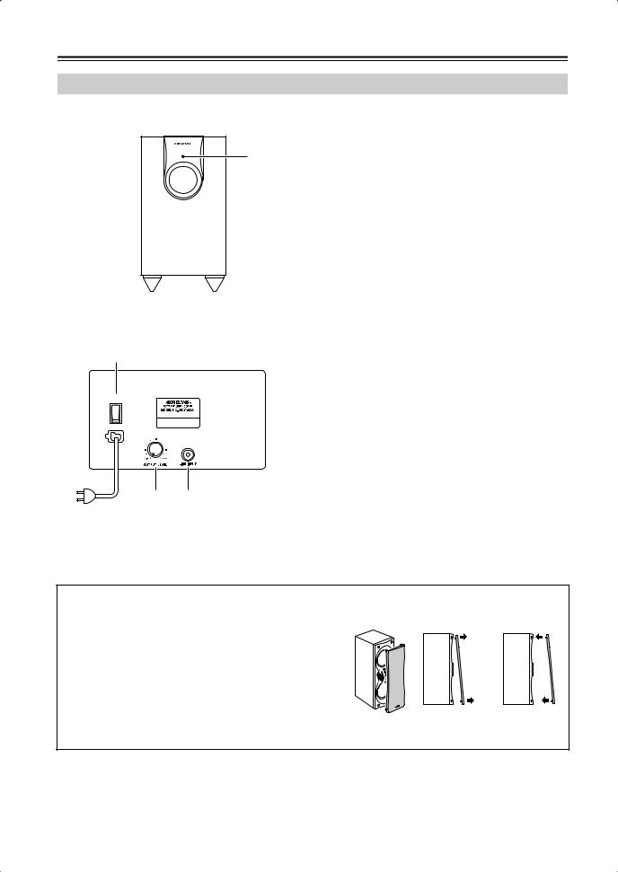
Speakers
Subwoofer (SKW-550)
For detailed information, see the pages in parentheses.
■ Front
1
■ Rear
4 (Not North American model)
 POWER
POWER
ON
OFF
2 3
To AC outlet
ASTANDBY/ON indicator
Red: Subwoofer in standby mode Green: Subwoofer on
With the Auto Standby function, the SKW-550 automatically turns on when an input signal is detected in Standby mode. When there’s no input signal for a while, the SKW-550 automatically enters Standby mode.
BOUTPUT LEVEL control (42)
This control is used to adjust the volume of the subwoofer.
CLINE INPUT (20)
This RCA input should be connected to the subwoofer pre out on the AV receiver with supplied RCA cable.
DPOWER switch (Not North American model) (36)
Press this switch to the ON position to turn on the power. Press it to the OFF position to turn off the power.
Note:
The Auto Standby function turns the subwoofer on when the input signal exceeds a certain level. If the Auto Standby function does not work reliably, try slightly increasing or decreasing the subwoofer output level on the AV receiver (page 59).
■Attaching and detaching the speaker grilles
Front and Center speakers have detachable grilles. Use the
following method to attach or detach the grilles. |
Removal |
Replacement |
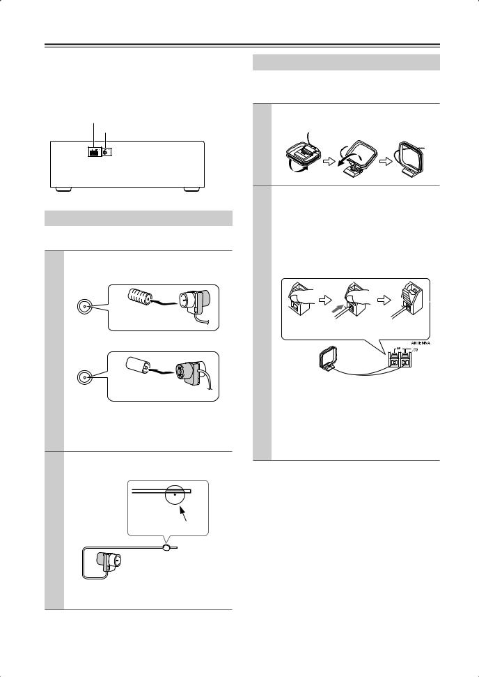
1. While holding the bottom edge of the speaker grille with your both hands, pull it gently toward you to remove the bottom of the grille.
2.In the same way, gently pull the upper edge of the speaker grille toward you to remove it from the main
unit.
3.To replace the grill, push the projections at the corners into the grille plug holes on the speaker cabinet.
18
Connecting Your Speakers
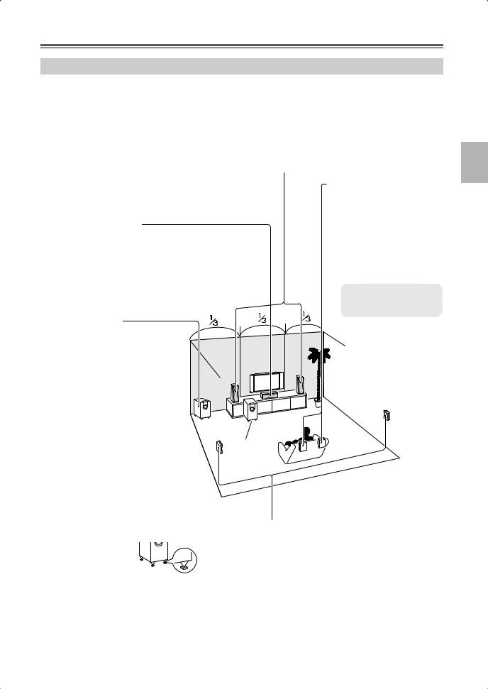
Enjoying Home Theater
Thanks to the AV receiver’s superb capabilities, you can enjoy surround sound with a real sense of movement in your own home—just like being in a movie theater or concert hall. You can enjoy DVDs featuring DTS and Dolby Digital. With analog and digital TV, you can enjoy Dolby Pro Logic IIx and Onkyo’s own DSP surround listening modes.
Front left and right speakers (SKF-550F)
These output the overall sound. Their role in a home theater is to provide a solid anchor for the sound image. They should be positioned facing the listener at about ear level, and equally spaced from the TV. Angle them inward slightly so as to create a triangle, with the listener at the apex.
Center speaker (SKC-550C)
This speaker enhances the front left and right speakers, making sound movements distinct and providing a full sound image. For movies it’s used mainly for dialog.
Position it close to your TV facing forward at about ear level, or at the same height as the front left and right speakers.
Subwoofer (SKW-550)
The subwoofer handles the bass sounds of the LFE (Low-Frequency Effects) channel. The volume and quality of the bass output from your subwoofer will depend on its position, the shape of your listening room, and your listening position. In general, a good bass sound can be obtained by installing the subwoofer in a front corner, or at one-third the way along the wall, as shown.
Tip: To find the best position for your sub- |
Corner |
|||
|
|
|||
woofer, while playing a movie or some |
|
|
||
music with good bass, experiment by plac- |
|
|
||
|
|
|||
ing your subwoofer at various positions |
|
|
||
within the room, and choose the one that |
|
|
||
provides the most satisfying results. |
|
|
||
|
|
|
||
If the subwoofer is placed on a hard floor |
|
|
||
(wood, vinyl, tile, etc.) and playback is very |
|
|
||
loud, the subwoofer's feet |
may damage |
the |
|
|
flooring. To prevent this, |
place the supplied |
|
|
|
pads underneath the sub |
- |
|
|
|
woofer's feet. The pads |
|
|
|
|
also provide a stable base |
|
|
||
for the subwoofer. |
|
|
||
|
|
|
|
|
Surround back left and right speakers (SKB-550)
These speakers are necessary to enjoy Dolby Digital EX, DTS-ES Matrix, DTS-ES Discrete. They enhance the realism of surround sound and improve sound localization behind the listener. Position them behind the listener about 2–3 feet (60–100 cm) above ear level.
* While speaker set B is on, these speakers output no sound.
1/3 wall length
Surround left and right speakers (SKM-550S)
These speakers are used for precise sound positioning and to add realistic ambience.
Position them at the sides of the listener, or slightly behind, about 2–3 feet (60–100 cm) above ear level. Ideally they should be equally spaced from the listener.
19
Connecting Your Speakers—Continued
Speaker Connection Precautions
Read the following before connecting your speakers:
•You can connect speakers with an impedance of between 8 and 16 ohms. If you use speakers with a lower impedance, and use the amplifier at high volume levels for a long period of time, the built-in amp protection circuit may be activated.
•Disconnect the power cord from the wall outlet before making any connections.
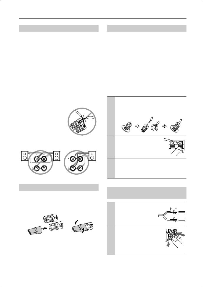
•Pay close attention to speaker wiring polarity. In other words, connect positive (+) terminals to only positive
(+) terminals, and negative (–) terminals to only negative (–) terminals. If you get them the wrong way around, the sound will be out of phase and will sound unnatural.
•Unnecessarily long or very thin speaker cables may affect the sound quality and should be avoided.
•Be careful not to short the positive and negative wires.
Doing so may damage the AV receiver.
• Don’t connect more than one cable to each speaker terminal. Doing so may damage the AV receiver.
• Don’t connect a speaker to several terminals.
Connecting Speaker Set A
The AV receiver’s positive (+) speaker terminals and speaker’s positive (+) terminals are color-coded for ease of identification. (The negative (–) speaker terminals are all black.) Match the color of each cable to the corresponding speaker terminal.
Speaker terminal |
Color |
|
|
Front left |
White |
|
|
Front right |
Red |
|
|
Center |
Green |
|
|
Surround left |
Blue |
|
|
Surround right |
Gray |
|
|
Surround back left |
Brown |
|
|
Surround back right |
Tan |
|
|
1 On the AV receiver, unscrew the terminal. Fully insert the bare wires. Make sure that the bare wire is touching the inside of the pole. Screw the terminal tight.
2 |
On the speakers, while pressing |
|
the terminal lever, insert the |
|
wire into the hole, and then |
|
release the lever. |
3 |
Using the supplied RCA cable, connect the AV |
receiver’s SUBWOOFER PRE OUT to LINE INPUT on the subwoofer.
Make sure the cable is plugged all the way.
Using the Speaker Terminal Tool
The supplied speaker terminal tool makes it easy to tighten and loosen the speaker terminals. If you are using banana plugs, to ensure optimum sound quality, tighten the speaker terminal before inserting the banana plug.
Connecting Speaker Set B (sold separately)
1 |
Strip 3/8" (10 mm) of insu- |
3/8" (10 mm) |
|
||
|
lation from the ends of the |
|
|
speaker cables, and twist |
|
|
the bare wires tightly, as |
|
|
shown. |
|
2 While pressing the lever, insert |
|
|
|
the wire into the hole, and then |
|
|
release the lever. |
|
|
Make sure that the terminals are |
|
|
gripping the bare wires, not the |
|
|
insulation. |
|
Note:
When speaker set B is turned on, speaker set A is reduced to 5.1-channel playback.
20
Connecting Your Speakers—Continued
The following illustration shows which speaker should be connected to each pair of terminals.
|
|
|
|
|
|
|
|
|
|
|
|
|
Speaker Set A (supplied) |
|
|
|
|
|
|
|
|||||
|
|
|
|
|
|
|
|
|
|
|
|
|
Front right |
|
Front left |
||||||||||
|
|
|
|
|
|
|
|
|
|
|
|
|
|
|
|
|
|
|
|
||||||
|
|
|
|
|
|
|
|
|
|
|
|
|
|
|
|
|
|
|
|
||||||
|
|
|
|
|
|
|
Surround |
Surround |
Surround |
Surround |
speaker |
|
speaker |
||||||||||||
Subwoofer |
back right |
back left |
|
right |
|
left |
|
|
|
|
|
|
|
||||||||||||
speaker |
speaker |
speaker |
speaker |
|
|
|
Center |
|
|
||||||||||||||||
|
|
|
|
|
|
|
|
|
|
|
|
|
|
|
|
|
|
|
|
|
|
speaker |
|
|
|
|
|
|
|
|
|
|
|
|
|
|
|
|
|
|
|
|
|
|
|
|
|
|
|
||
|
|
|
|
|
|
|
|
|
|
|
|
|
|
|
|
|
|
|
|
|
|
|
|
|
|
|
|
|
|
|
|
|
|
|
|
|
|
|
|
|
|
|
|
|
|
|
|
|
|
|
|
|
|
|
|
|
|
|
|
|
|
|
|
|
|
|
|
|
|
|
|
|
|
|
|
|
|
|
|
|
|
|
|
|
|
|
|
|
|
|
|
|
|
|
|
|
|
|
|
|
|
|
|
SURROUND BACK |
SURROUND |
FRONT |
CENTER |
SPEAKERS |
SPEAKERS |
SPEAKERS A |
SPEAKER |
L |
|
|
L |
R |
|
|
R |
|
IN 2 |
IN 1 |
OUT |
HDMI |
ANTENNA |
|
|
SIRIUS |
XM |
|
|
|
|
ASSIGNABLE |
|
|
|
|
|
|
|
||||
DIGITAL IN |
|
|
|
AM |
|
FM 75 |
|
|
L |
|
|
L |
|
|
|
|
|
|
|
|
|
|
|||
ASSIGNABLE |
|
|
|
|
|
|
|
|
|
|
|
|
COAX- |
|
|
|
|
|
|
|
|
|
|
|
|
IAL1 |
|
|
Y |
|
|
|
|
|
|
|
|
|
|
|
|
|
CBL/SAT |
VCR/DVR |
DVD |
MONITOR |
|
|
|
|
|
|
|
|
|
|
|
|
|
OUT V |
|
|
|
|
2 |
|
|
CB/PB |
V |
|
|
|
|
R |
|
|
R |
OPTICAL |
|
|
|
|
|
|
|
S |
|
|
|
|
1 |
|
|
CR/PR |
S |
|
|
|
|
|
|
|
|
|
|
|
|
|
|
|
|
|
SURROUND BACK |
SURROUND |
FRONT |
|
|
CBL/SAT IN VCR/DVR IN |
DVD IN |
OUT |
IN |
OUT |
IN |
IN |
|
SPEAKERS |
SPEAKERS |
SPEAKERS A |
|
|
COMPONENT VIDEO |
|
|
|
|
|
|
|||||
2 |
IN |
OUT |
IN |
IN |
OUT |
IN |
FRONT |
SURROUND CENTER |
SURR BACK |
|
PRE OUT |
|
|
|
L |
||||||||||
|
|
|
|
|
|
|
|
|
|
|
|
SUB |
|
L |
|
L |
L |
|
|
|
|
|
L |
|
WOOFER |
|
R |
|
R |
|
|
|
|
|
|
|
|
R |
|
|
R |
|
|
|
|
|
R |
|
|
||
REMOTE |
|
|
|
|
|
|
|
|
SUB |
|
|
FRONT |
CONTROL |
CD |
TAPE |
|
CBL/SAT |
VCR/DVR |
|
DVD |
WOOFER |
|
|
||
|
|
|
|
|
|
SPEAKERS B |
||||||
|
|
|
|
|
|
|
|
|
|
|
|
|
|
|
|
|
|
|
|
|
|
|
|
|
|
|
|
|
|
|
|
|
|
|
|
|
|
|
|
|
|
|
|
|
|
|
|
|
|
|
|
|
|
|
|
|
|
|
|
|
|
|
|
|
|
|
|
|
|
|
|
|
|
|
|
|
|
|
|
|
|
|
|
|
|
|
|
|
|
|
|
|
|
|
|
|
|
|
|
|
|
|
|
|
|
|
|
|
|
|
|
|
|
|
|
|
|
|
|
|
|
|
|
|
|
|
|
|
|
|
|
|
|
|
|
|
|
|
|
|
|
|
|
|
|
|
Front right |
Front left |
||||
|
|
|
|
|
|
|
|
|
|
|||||||
|
|
|
|
|
|
|
|
|||||||||
|
|
|
|
|
|
|
|
|
|
|
speaker |
speaker |
||||
|
|
|
|
|
|
|
|
|
|
|
||||||
Speaker Set B
Wall Mounting
The speakers can easily be mounted on a wall by using the attached wall brackets.
To mount a front, surround, or surround back speaker vertically, use its wall bracket, as shown, to hang it on a screw that's securely screwed into the wall.
To mount the center speaker horizontally, use its two wall brackets, as shown, to hang it on two screws that are securely screwed into the wall.
 Wall brackets
Front speaker |
Surround and |
(SKF-550F) |
Surround back speaker |
|
(SKM-550S/SKB-550) |
13" (330 mm) |
Center speaker (SKC-550C)
Caution:
A mounting screw’s ability to support a speaker depends on how well it’s anchored to the wall. If you have hollow walls, screw each mounting screw into a stud. If there are no studs, or the walls are solid, use suitable wall anchors.
Use screws with a head diameter of 5/16" (9 mm) or less and a shank diameter of 1/8" (4 mm) or less. With hollow walls, use a cable/pipe detector to check for any power cables or water pipes before making any holes.
Leave a gap of between 5/16" (7 mm) and 7/16" (10 mm) between the wall and the base of the screw head, as shown.
(We recommend that you consult a home installation professional.)
Wall
5/16" – 7/16" (7 mm) – (10 mm)
21
Connecting Antennas
This section explains how to connect the supplied indoor FM antenna and AM loop antenna, and how to connect commercially available outdoor FM and AM antennas. The AV receiver won’t pick up any radio signals without any antenna connected, so you must connect the antenna to use the tuner.
 AM antenna push terminals
 FM antenna jack
|
ANTENNA |
AM |
FM 75 |
Connecting the AM Loop Antenna
The supplied indoor AM loop antenna is for indoor use only.
1 Assemble the AM loop antenna, inserting the tabs into the base, as shown.
Connecting the Indoor FM Antenna
The supplied indoor FM antenna is for indoor use only.
1 Attach the FM antenna, as shown.
■ American Model
 FM 75
FM 75
Insert the plug fully into the jack.
■ Other Models
 FM 75
FM 75
Insert the plug fully into the jack.
Once your AV receiver is ready for use, you’ll need to tune into an FM radio station and adjust the position of the FM antenna to achieve the best possible reception.
2 Use thumbtacks or something similar to fix the FM antenna into position.
Thumbtacks, etc.
Caution: Be careful that you don’t injure yourself when using thumbtacks.
If you cannot achieve good reception with the supplied indoor FM antenna, try a commercially available outdoor FM antenna instead (see page 23).
2 Connect both wires of the AM loop antenna to the AM push terminals, as shown.
(The antenna’s wires are not polarity sensitive, so they can be connected either way around). Make sure that the wires are attached securely and that the push terminals are gripping the bare wires, not the insulation.
Push |
Insert wire |
Release |
Once your AV receiver is ready for use, you’ll need to tune into an AM radio station and adjust the position of the AM antenna to achieve the best possible reception.
Keep the antenna as far away as possible from your AV receiver, TV, speaker cables, and power cords.
If you cannot achieve good reception with the supplied indoor AM loop antenna, try using it with a commercially available outdoor AM antenna (see page 23).
22
Loading...