


MiniDisc Recorder
MD-105X
Operating Instructions
|
MINDISC RECODER |
|
AMCS |
|
|
|
|
PUSH TO ENTER |
|
|
|
DISC LOADING MECHANISM0 |
|
|
STANDBY/ON |
CD |
|
|
|
|
|
|
|
|
|
DUBBING |
REC |
|
|
|
|
|
|
|
STANDBY |
|
|
|
|
INPUT |
|
DISPLAY |
EDIT/NO |
YES |
MO ST D1 D2 |
|
|
|
|
ANALOG |
|
|
|
|
|
|
|
MD-105X |
|
English
using Before
Connections
Operations
Information Other
Before using
Thank you for purchasing ...
Thank you for purchasing the ONKYO MD-105X MD Recorder.
Please read this manual thoroughly before making connections and plugging in the unit.
Following the instructions in this manual will enable you to obtain the optimum performance and listening enjoyment from your new MD-105X.
Please retain this manual for future reference.
Main Features
• 24-Bit A/D and D/A Converters • Digital Rec Level Adjustment
• Rec Volume Control for Analog and Digital Inputs
• Album Dubbing and Fade Out Control • Unique "Dub It" Feature
• Monaural Recording • One-Touch Dubbing • Signal Synchro Recording
Memory Preservation
This unit does not require memory preservation batteries. A built-in memory power back-up system preserves the contents of the memory during power failures and even when the unit is unplugged. The unit must be plugged-in in order to charge the back-up system.
The memory preservation period after the unit has been unplugged varies depending on climate and placement of the unit. On the average, memory contents are protected over a period of a few weeks after the last time the unit was unplugged. This period is shorter when the unit is exposed to a highly humid climate.
Declaration of Conformity
We, ONKYO EUROPE ELECTRONICS GmbH INDUSTRIESTRASSE 20 82110 GERMERING, GERMANY
declare in own responsibility, that the ONKYO product described in this instruction manual is in compliance with the corresponding technical standards such as EN60065, EN55013, EN55020 and EN61000-3-2, -3-3 (or EN60555-2, -3)
GERMERING, GERMANY
K.OTSU
ONKYO EUROPE ELECTRONICS GmbH
U.S. and foreign patents licensed from Dolby Laboratories Licensing Corporation.
WARNING:
TO REDUCE THE RISK OF FIRE OR ELECTRIC SHOCK, DO NOT EXPOSE THIS APPLIANCE TO RAIN OR MOISTURE.
CAUTION:
TO REDUCE THE RISK OF ELECTRIC SHOCK, DO NOT REMOVE COVER (OR BACK). NO USER-SERVICEABLE PARTS INSIDE. REFER SERVICING TO QUALIFIED SERVICE PERSONNEL.
WARNING |
|
AVIS |
RISK OF ELECTRIC SHOCK |
|
RISQUE DE CHOC ELECTRIQUE |
DO NOT OPEN |
|
NE PAS OUVRIR |
The lightning flash with arrowhead symbol, within an equilateral triangle, is intended to alert the user to the presence of uninsulated “dangerous voltage” within the product’s enclosure that may be of sufficient magnitude to constitute a risk of electric shock to persons.
The exclamation point within an equilateral triangle is intended to alert the user to the presence of important operating and maintenance (servicing) instructions in the literature accompanying the appliance.
2
Important Safeguards
1.Read Instructions – All the safety and operating instructions should be read before the appliance is operated.
2.Retain Instructions – The safety and operating instructions should be retained for future reference.
3.Heed Warnings – All warnings on the appliance and in the operating instructions should be adhered to.
4.Follow Instructions – All operating and use instructions should be followed.
5.Water and Moisture – The appliance should not be used near water – for example, near a bathtub, washbowl, kitchen sink, laundry tub, in a wet basement, or near a swimming pool, and the like.
6.Carts and Stands – The appliance should be used only with a cart or stand that is recommended by the manufacturer.
6A. An appliance and cart combination should be moved with care. Quick stops, excessive force, and uneven surfaces may cause the appliance and cart combination to overturn.
PORTABLE CART WARNING
S3125A 
7.Wall or Ceiling Mounting – The appliance should be mounted to a wall or ceiling only as recommended by the manufacturer.
8.Ventilation – The appliance should be situated so that its location or position does not interfere with its proper ventilation. For example, the appliance should not be situated on a bed, sofa, rug, or similar surface that may block the ventilation openings; or if placed in a built-in installation, such as a bookcase or cabinet that may impede the flow of air through the ventilation openings, there should be free space of at least 5 cm (2 in.) and an opening behind the appliance.
9.Heat – The appliance should be situated away from heat sources such as radiators, heat registers, stoves, or other appliances (including amplifiers) that produce heat.
10.Power Sources – The appliance should be connected to a power supply only of the type described in the operating instructions or as marked on the appliance.
11.Polarization – If the appliance is provided with a polarized plug having one blade wider than the other, please read the following information:
The polarization of the plug is a safety feature. The polarized plug will only fit the outlet one way. If the plug does not fit fully into the outlet, try reversing it. If there is still trouble, the user should seek the services of a qualified electrician. Under no circumstances should the user attempt to defeat the polarization of the plug.
12.Power-Cord Protection – Power-supply cords should be routed so that they are not likely to be walked on or pinched by items placed upon or against them, especially near plugs, convenience receptacles, and the point where they exit from the appliance.
13.Cleaning – The appliance should be cleaned only as recommended by the manufacturer.
14.Nonuse Periods – The power cord of the appliance should be unplugged from the outlet when left unused for a long period of time.
15.Object and Liquid Entry – Care should be taken so that objects do not fall and liquids are not spilled into the enclosure through openings.
16.Damage Requiring Service – The appliance should be serviced by qualified service personnel when:
A.The power-supply cord or the plug has been damaged; or
B.Objects have fallen, or liquid has been spilled into the appliance; or
C.The appliance has been exposed to rain; or
D.The appliance does not appear to operate normally or exhibits a marked change in performance; or
E.The appliance has been dropped, or the enclosure damaged.
17.Servicing – The user should not attempt to service the appliance beyond that described in the operating instructions. All other servicing should be referred to qualified service personnel.
Using Before
Connections
Operations
Information Other
3

Precautions
1. Warranty Claim
You can find the serial number on the rear panel of this unit. In case of warranty claim, please report this number.
2. Recording Copyright
Recording of copyrighted material for other than personal use is illegal without permission of the copyright holder.
3. Power
WARNING
BEFORE PLUGGING IN THE UNIT FOR THE FIRST TIME, READ THE FOLLOWING SECTION CAREFULLY.
The voltage of the available power supply differs according to country or region. Be sure that the power supply voltage of the area where this unit will be used meets the required voltage (e.g., AC 230 V, 50 Hz or AC 120 V, 60 Hz) written on the rear panel.
Turning off the standby button does not shut off the power completely. So the power cord should be removed from the AC outlet when the unit is not used for a prolonged time.
4.Do not touch this unit with wet hands
Do not handle this unit or power cord when your hands are wet or damp. If water or any other liquid enters the case, take this unit to an authorized service center for inspection.
5.Location of this unit
Place this unit in a well-ventilated location.
Take special care to provide plenty of ventilation on all sides of this unit especially when it is placed in an audio rack. If ventilation is blocked, this unit may overheat and malfunction.
Do not expose this unit to direct sunlight or heating units as this unit’s internal temperature may rise and shorten the life of the pickup.
Avoid damp and dusty places and places directly affected by vibrations from the speakers. In particular, avoid placing the unit on or above one of the speakers.
Be sure this unit is placed in a horizontal position. Never place it on its side or on a slanted surface as it may malfunction.
Do not place near tuners or TV sets.
If placed next to a TV or tuner, it may cause reception interference resulting in some noise in the TV or tuner output.
6. Care
From time to time you should wipe the front and rear panels and the cabinet with a soft cloth. For heavier dirt, dampen a soft cloth in a weak solution of mild detergent and water, wring it out dry, and wipe off the dirt. Following this, dry immediately with a clean cloth.
Do not use rough material, thinners, alcohol or other chemical solvents or cloths since these could damage the finish or remove the panel lettering.
7. Points to remember
If this unit is brought from a cold environment to a warm one or is in a cold room that is quickly heated, condensation may form on the pickup, preventing proper operation. In this case, remove the disc and leave the power ON for about one hour to remove the condensation.
When transporting this unit, be careful not to bump it.
DANGER:
INVISIBLE LASER RADIATION WHEN OPEN AND INTERLOCK FAILED OR DEFEATED. AVOID DIRECT EXPOSURE TO BEAM.
CAUTION:
THIS PRODUCT UTILIZES A LASER. USE OF CONTROLS OR ADJUSTMENTS OR PERFORMANCE OF PROCEDURES OTHER THAN THOSE SPECIFIED HEREIN MAY RESULT IN HAZARDOUS RADIATION EXPOSURE.
4

Precautions(continued)
For U.S. model
The laser is covered by a housing which prevents exposure d uring operation or maintenance. However, this product is classified as a Laser Product by CDRH (Center for Devices and Radiological Health) which is a department of the Food and Drug Administration. According to their regulations 21 CFR section 1002.30, all manufactures who sell Laser Products must maintain records of written communications between the manufacturer, dealers and customers concerning radiation safety. If you have any complaints about instructions or explanations affecting the use of this product, please feel free to write to the address on the back page of this manual. When you write us, please include the model number and serial number of your unit.
In compliance with Federal Regulations, the certification, identification and the period of manufacture are indicated on the rear panel.
FCC INFORMATION FOR USER
CAUTION:
The user changes or modifications not expressly approved by the party responsible for compliance could void the user’s authority to operate the equipment.
NOTE:
This equipment has been tested and found to comply with the limits for a Class B digital device, pursuant to Part 15 of the FCC Rules. These limits are designed to provide reasonable protection against harmful interference in a residential installation. This equipment generates, uses and can radiate radio frequency energy and, if not installed and used in accordance with the instructions, may cause harmful interference to radio communications. However, there is no guarantee that interference will not occur in a particular installation. If this equipment does cause harmful interference to radio or television reception, which can be determined by turning the equipment off and on, the user is encouraged to try to correct the interference by one or more of the following measures:
• Reorient or relocate the receiving antenna.
•Increase the separation between the equipment and receiver.
•Connect the equipment into an outlet on a circuit different from that to which the receiver is connected.
•Consult the dealer or an experienced radio/TV technician for help.
Using Before
Connections
Operations
Information Other
5

Precautions(continued)
For Canadian model
CAUTION: THIS DIGITAL APPARATUS DOES NOT EXCEED THE CLASS B LIMITS FOR RADIO NOISE EMISSION FROM DIGITAL APPARATUS SET OUT IN THE RADIO INTERFERENCE REGULATIONS OF THE CANADIAN DEPARTMENT OF COMMUNICATIONS.
For models having a power cord with a polarized plug:
CAUTION: TO PREVENT ELECTRIC SHOCK, MATCH WIDE BLADE OF PLUG TO WIDE SLOT, FULLY INSERT.
Modele pour les Canadien
ATTENTION: L’ I N T E R F É R E N C E R A D I O ÉLECTRIQUE GÉNÉRÉE PAR CET APPAREIL NUMÉRIQUE DE TYPE B NE DÉPASSE PAS LES LIMITES ÉNONCÉES DANS LE RÈGLEMENT SUR LES PERTURBATIONS RADIO ÉLECTRIQUES, SECTION APPAREIL NUMÉRIQUE, DU MINISTÈRE DES COMMUNICATIONS.
Sur les modèles dont la fiche est polarisée:
ATTENTION: POUR ÉVITER LES CHOCS ÉLECTRIQUES, INTRODUIRE LA LAME LA PLUS LARGE DE LA FICHE DANS LA BORNE CORRESPONDANTE DE LA PRISE ET POUSSER JUSQU’AU FOND.
For European model
This unit contains a semiconductor laser system and is classified as a “CLASS 1 LASER PRODUCT”. So, to use this model properly, read this Instruction Manual carefully. In case of any trouble, please contact the store where you purchased the unit. To prevent being exposed to the laser beam, do not try to open the enclosure.
“CLASS 1 LASER
PRODUCT”
This label on the left hand panel states that:
1.This unit is a CLASS 1 LASER PRODUCT and employs a laser inside the cabinet.
2.To prevent the laser from being exposed, do not remove the cover. Refer servicing to qualified personnel.
For British model
Replacement and mounting of an AC plug on the power supply cord of this unit should be performed only by qualified service personnel.
IMPORTANT
The wires in the mains lead are coloured in accordance with the following code:
Blue : Neutral Brown : Live
As the colours of the wires in the mains lead of this apparatus may not correspond with the coloured markings identifying the terminals in your plug, proceed as follows:
The wire which is coloured blue must be connected to the terminal which is marked with the letter N or coloured black.
The wire which is coloured brown must be connected to the terminal which is marked with the letter L or coloured red.
IMPORTANT
A 5 amp fuse is fitted in this plug. Should the fuse need to be replaced, please ensure that the replacement fuse has a rating of 5 amps and that it is approved by ASTA or BSI to BS1362. Check for the ASTA mark or the BSI mark on the body of the fuse.
IF THE FITTED MOULDED PLUG IS UNSUITABLE FOR THE SOCKET OUTLET IN YOUR HOME, THEN THE FUSE SHOULD BE REMOVED AND THE PLUG CUT OFF AND DISPOSED OF SAFELY. THERE IS A DANGER OF SEVERE ELECTRICAL SHOCK IF THE CUT OFF PLUG IS INSERTED INTO ANY 13 AMP SOCKET.
If in any doubt, please consult a qualified electrician.
6

Table of contents |
|
Before Using |
|
Checking the supplied accessories ............................................... |
Below |
Using the remote controller ................................................................ |
8 |
Connections |
|
Connecting to the Onkyo Separate Collection series components....... |
9 |
Connecting to the other components............................................... |
10 |
Operations |
|
Normal play ..................................................................................... |
14 |
Random play .................................................................................... |
18 |
Repeat play ...................................................................................... |
19 |
Memory play .................................................................................... |
21 |
CD-dubbing ..................................................................................... |
23 |
Analog recording ............................................................................. |
25 |
Digital recording .............................................................................. |
28 |
Signal Synchro recording .................................................................. |
31 |
System operation ............................................................................. |
32 |
Other information for recording ....................................................... |
36 |
Editing the contents of an MD ......................................................... |
37 |
Naming a track or disc ..................................................................... |
42 |
Canceling the last editing ................................................................. |
45 |
Other Information |
|
Message list ..................................................................................... |
46 |
System limitations ............................................................................ |
47 |
Rules for digital recording ................................................................ |
48 |
Troubleshooting ............................................................................... |
49 |
Precautions for handling the MiniDisc (MD) ...................................... |
51 |
Indexed to parts and controls ........................................................... |
52 |
Specifications ................................................................................... |
56 |
Checking the supplied accessories |
|
Check that the following accessories are supplied with this unit. |
|
• z remote control cable x1 • Audio connection cable x2 • Optical fiber cable x1
• Remote controller x1 |
• Dry batteries UM-3 x2 |
RC-409MD |
|
Using Before
Connections
Operations
Information Other
7
Using the remote controller
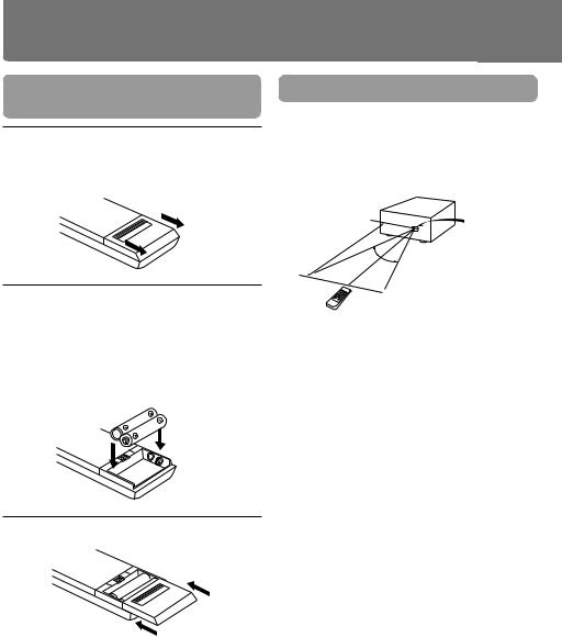
Inserting the remote controller batteries
1 Remove the battery compartment cover by opening it as shown in the illustration.
2 Insert two AA (R6 or UM-3)-size batteries into the battery compartment.
Carefully follow the polarity diagram (positive(+) and negative (–) symbols) inside the battery compartment.
3 Replace the compartment cover.
Notes
•Do not mix new batteries with old batteries or differnt kinds of batteries.
•To avoid corrosion, remove the batteries if the remote controller is not to be used for a long time.
•Remove dead batteries immediately to avoid damage from corrosion. If the remote controller doesn't operate smoothly, replace both the batteries at the same time.
•The life of the batteries supplied is about six months but this will vary depending on usage.
Using the remote controller
Point the remote controller toward the remote control sensor.
With the supplied remote controller (RC-409MD)
MD-105X
Remote
5m |
control sensor |
30° 30°
RC-409MD
Point the remote controller toward
MD-105X’s remote control sensor.
•Place the unit away from strong light such as direct sunlight or inverted flourescent light which can prevent proper operation of the remote contoroller.
•Using another remote controller of the same type in the same room or using the unit near equipment which uses infrared rays may cause operational interference.
•Do not put any object such as a book on the remote contoroller. The buttons of the remote contoroller may be pressed by mistake and drain the batteries.
•Make sure the audio rack doors do not have colored glass. Placing the unit behind such doors may prevent proper remote contoroller operation.
•If there is any obstacle between the remote contoroller and the remote control sensor, the remote controller will not operate.
8
Using the remote controller(continued)
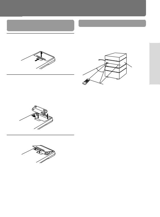
Inserting the remote controller batteries
1 Remove the battery compartment cover by pressing the tab and lifting up the cover.
2 Insert two AA (R6 or UM-3)-size batteries into the battery compartment.
Carefully follow the polarity diagram (positive(+) and negative (–) symbols) inside the battery compartment.
3 Replace the compartment cover.
Notes
•Do not mix new batteries with old batteries or differnt kinds of batteries.
•To avoid corrosion, remove the batteries if the remote controller is not to be used for along time.
•remove dead batteries immediately to avoid damage from corrosion.if the remote controller doesn't operate smoothly, replace both the batteries at the same time.
•The life of the batteries supplied is about six months but this Will vary depending on usage.
Using the remote controller
Point the remote controller toward the remote control sensor.
With RC-398S
(supplied with A-905X amplifier)
Remote control sensor
A-905X
30°
30°
5m
RC-398S
Point the remote controller toward
A-905X’s remote control sensor.
•Place the unit away from strong light such as direct sunlight or inverted flourescent light which can prevent proper operation of the remote contoroller.
•Using another remote controller of the same type in the same room or using the unit near equipment which uses infrared rays may cause operational interference.
•Do not put any object such as a book on the remote contoroller. The buttons of the remote contoroller may be pressed by mistake and drain the batteries.
•Make sure the audio rack doors do not have colored glass. Placing the unit behind such doors may prevent proper remote contoroller operation.
•If there is any obstacle between the remote contoroller and the remote control sensor, the remote controller will not operate.
Using Before
Connections
Operations
Information Other
9

Connections
Connecting to the Onkyo Separate Collection series components
This section introduces you to the other Separate Collection Series system components and their convenient system functions, followed by connecting instructions.
The following Separate Collection series components are commercially available:
•T-405X ........ Stereo Tuner
•A-905X ....... Integrated Stereo Amplifier
•K-505X ....... Stereo Cassette Tape Deck
•C-705X ....... Compact Disc (CD) Player (Not available in U.S.A and Canada)
•C-707CH .... Compact Disc (CD) Changer (Only available in U.S.A. and Canada)
Note that the available components may vary according to the area.
Combination use of the unit with the above system components enables you to operate the following convenient functions.
•Auto Power On
–You can turn on the power to the amplifier by pressing the STANDBY/ON button on one of the system components.(The amplifier's POWER switch must be set to ON.)
–When the amplifier's POWER switch is set to ON, you can turn on the power to all the system components simultaneously by pressing the STANDBY/ON button the amplifier.
Afterwards, you can turn off the power to the individual components that are not in use.
•Direct Change
Pressing the n button of the MD-105X automatically selects the “MD” input source on the A-905X before playing the MD.
•Remote control of the System Components
You can control the operation of this MD recorder using the A-905X's remote controller.
•Program Timer
You can record the desired broadcasting programs or play your favorite MD at a specified time using the T-405X’s built-in timer. (Refer to the T-405X instruction manual for details.)
•Sleep Timer
You can fall asleep to a music/radio program with the timer. (Refer to the T-405X instruction manual for details.)
•CD-dubbing
You can start recording from a CD player to your MD-105X by pressing the CD DUBBING button.
•CD-synchro Recording
When this function is enabled, you can immediately start recording to the MD by pressing the s button on the CD player. (Refer to page 32 for details.)
•Cassette-synchro Recording
When this function is enabled, you can start recording to the MD by pressing the s button on the cassette deck. (Refer to page 33 for details.)
10
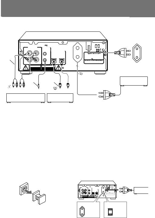
Connecting to the other components
Before connecting
•Do not connect the unit's AC power cord to a wall outlet until you have completed all the other connections.
•On each pair of connectors, a red connector (marked R) corresponds to the right channel, and a white connector (marked L) to the left channel. Connect white plugs of audio connection cables to L connectors and connect red pugs of audio connection cables to R connectors.
|
Audio conection cable |
To L connectors (White) |
(White) To L connectors |
To R connectors (Red) |
(Red) To R connectors |
Improper connection |
|
Using Before
 Insert completely
•Insert the plug securely. If the connection is incomplete, noise or malfunction may result.
•When you use a digital audio optical cable, do not bend it sharply nor coil it tightly.
•Bundling an audio connection cable with the power cord or speaker cord may degrade the sound quality.
•To use the unit with the other Onkyo Separate Collection series components, follow the connection diagram in the A-905X instruction manual to connect the unit to the system.
Note:
The 230 V model is show in the following illustrations.
Connections
Operations
Information Other
11
Connecting to the other components
• This unit use heat-sensitive parts. Do not place this unit on the Amplitier or Receiver.
Connections
Audio connection cable
ANALOG |
REMOTE |
US AND FOREIGN PATENTS LICENSED |
||
FROM DOLBY LABORATORIES. |
||||
INPUT |
OUTPUT |
CONTROL |
|
|
(REC) |
(PLAY) |
|
DIGITAL INPUT |
|
|
|
|
||
L |
|
L |
|
OPTICAL |
|
1 |
2 |
||
R |
|
R |
|
|
WARNING |
AVIS |
RISK OF ELECTRIC SHOCK |
RISQUE DE CHOC ELECTRIQUE |
DO NOT OPEN |
NE PAS OUVRIR |
AC OUTLET
AC230V 50Hz UNSWITCHED 100W MAX.
MINIDISC RECORDER
MODEL NO. MD-105X
RATING:
AC230V 50Hz 11W
2-1, NISSHIN-CHO, NEYAGAWA-SHI,OSAKA, JAPAN MADE IN JAPAN
|
|
z cable |
Optical fiber |
|
|
|
cable |
L R |
L R |
|
|
OUT |
IN |
z |
OUT |
|
|
Amplifier
CD player,
DAT deck, etc.
To wall outlet
1 Connection with the Amplifier
Connect the MD-105X to the MD (or TAPE) jacks of your amplifier.
2 Connection to the Digital Input
Terminals (DIGITAL INPUT 1, 2)
You can perform digital recording on the MD105X if a CD (Compact Disc) player or DAT (Digital Audio Tapedeck) equipped with a digital (OPTICAL) output terminal is available. For digital recording, you need to connect the equipment to either DIGITAL INPUT 1 or 2 terminal using the supplied optical cable. These terminals can also be used for connecting an amplifier which is equipped with a digital output terminal.
•Terminal protection caps are attached to the DIGITAL INPUT terminals. Remove the cap for the terminal you wish to use when connecting the MD-105X to digital equipment. Replace the caps if you are not using the DIGITAL INPUT terminals.
3Connection to AC outlet (UNSWITCHED)
The power cord of another unit can be connected to this outlet.
Note
The shape, number, and total capacity of the AC outlets may differ depending on the area where the unit is purchased.
230 V, 50 Hz model: Capacity is 100 W in total. 120 V, 60 Hz model: Capacity is 120 W in total.
Note
•If the DIGITAL INPUT 2 is used for connecting the amplifier, you cannot use the full capability of the MD-105X.
•If you attempt to perform digital recording using a digital input terminal which is not connected, “D.In Unlock” will appear.
|
|
|
UP 27122647 |
|
|
|
|
ANALOG |
|
US AND FOREIGN PATENTS LICENSED |
|
|
|
||
|
REMOTE FROM DOLBY LABORATORIES. |
|
|
|
|||
INPUT |
OUTPUT |
|
CONTROL |
|
|
|
|
(REC) |
(PLAY) |
|
DIGITAL INPUT |
|
|
|
|
|
|
|
|
|
|
||
L |
|
L |
|
OPTICAL |
|
|
|
|
1 |
2 |
MINIDISC RECORDER |
||||
|
|
|
|
|
MODEL NO. MD-105X |
||
|
|
|
|
|
RATING: |
50Hz |
11W |
R |
|
R |
|
|
AC230V |
||
|
|
|
|
|
|
||
|
|
|
|
|
2-1, NISSHIN-CHO, NEYAGAWA-SHI,OSAKA, |
||
|
|
|
|
|
JAPAN |
MADE IN JAPAN |
|
WARNING |
|
AVIS |
|
AC OUTLET |
|
|
|
|
|
AC230V 50Hz |
|
|
|||
RISK OF ELECTRIC SHOCK RISQUE DE CHOC ELECTRIQUE |
|
UNSWITCHED |
|
|
|||
|
DO NOT OPEN |
|
NE PAS OUVRIR |
|
100W MAX. |
|
|
230V, 50Hz models |
120V, 60Hz models |
Capacity is |
Capacity is |
100 wats. |
120 wats. |
12

Connecting to the other components (continued)
Connecting the (z) controller
If you are using other ONKYO components equipped with z connectors, you can control these components using the amplifier's remote cnotroller.
Before connecting
•The amplifier must be connected in the z system hookups for z control operation.
•Each component has two z connentors. There is no differents between those connectors.
•The components may be connected in any order.
•Remote control operation is not possible if only the z remote control cable is connected to the z connectors.Connect the audio connection cables correctly.
Tuner
Amplifier
MD-105X |
z cable |
CD player
Connecting the AC power cord (mains lead)
Insert the AC power cord into a wall outlet. The STANDBY indicator lights.
 STANDBY/ON
 STANDBY
•To use the unit with the other Onkyo Separate Collection series components, follow the connection diagram in the A-905X instruction manual to connect the unit to the system.
•If you press the EJECT button whil the unit is in the STANDBY mode, the power will turn on and the display will light up automatically.
Using Before
Connections
Operations
Information Other
13

Operations
Normal play
|
|
r e |
RC-409MD (supplied) RC-398S (supplied |
||||
|
|
|
|
|
|
|
with A-905X) |
|
|
POWER |
POWER |
|
|
|
EJECT EJECT |
MINDISC RECODER |
|
AMCS |
|
|
|
|
|
|
|
PUSH TO ENTER |
|
|
|
|
POWER INPUT SELECTOR |
|
|
|
|
|
|
|
|
|
|
n |
|
PLAY MODE |
|
|
|
|
|
CONTINUE RANDOM |
MEMORY |
|
|
||
|
DISC LOADING MECHANISM0 |
A |
B |
C |
D |
E |
|
|
|
1F |
G2 |
H3 |
4I |
5J |
|
STANDBY/ON |
|
|
6 |
7 |
8 |
9 |
10 |
CD |
|
|
K |
L |
M |
N |
O |
DUBBING |
|
REC |
|
|
13 |
14 |
|
|
|
11 |
12 |
15 |
|||
|
|
|
P |
Q |
R |
S |
T |
|
16 |
17 |
18 |
19 |
20 |
STANDBY |
U |
V |
W |
X |
Y |
|
|
|
|
|
INPUT |
DISPLAY |
EDIT/NO |
YES |
21 |
22 |
23 |
24 |
25 |
MO ST D1 D2 |
|
|
|
Z |
|
|
|
|
|
|
|
|
>25 |
|
|
|
|
ANALOG |
e |
MD-105X
SCROLL DISPLAY NAME
e |
s |
s |
g |
g |
|
1 Press the STANDBY/ON button. (or the POWER button on the remote controller)
The STANDBY indicator goes out.
 STANDBY/ON (RC-409MD)
POWER
 STANDBY
DIGITAL IN 1
L |
|
|
|
|
|
1 |
2 |
3 |
4 |
5 |
|
40 |
20 |
10 |
6 |
2 |
0 |
6 |
7 |
8 |
9 |
10 |
|
R |
|
|
|
|
|
11 |
12 |
13 |
14 |
15 |
15 |
2 Insert an MD.
DIGITAL IN 1
The MD recorder reads TOC (Table Of Contents) information on the MD to display the total number of tracks and total playing time.
MINDISC RECODER |
AMCS |
|
PUSH TO ENTER |
DISC LOADING MECHANISM0
STANDBY/ON
CD
DUBBING
REC
STANDBY
INPUT |
DISPLAY EDIT/NO |
YES |
MO ST D1 D2 |

 ANALOG
MD-105X
The total number of tracks
DIGITAL IN 1
L |
|
|
|
|
|
1 |
2 |
3 |
4 |
5 |
|
40 |
20 |
10 |
6 |
2 |
0 |
6 |
7 |
8 |
9 |
10 |
|
R |
|
|
|
|
|
11 |
12 |
13 |
14 |
15 |
15 |
Current track number
•When an MD recorded with a disc name (title) is inserted, the disc name is displayed. If the disc name is too long and you cannot view the entire name, press the SCROLL button on your remote controller to shift the display.
14
Normal play (continued) |
|
|
|
|
|
|
|
|
|
|
|
|
|
RC-409MD (supplied) |
RC-398S (supplied with |
||||||
|
|
|
|
|
|
|
|
|
|
A-905X) |
MINDISC RECODER |
|
|
POWER |
|
|
|
EJECT |
|
|
|
AMCS |
|
|
|
|
|
|
|
|
|
|
|
PUSH TO ENTER |
|
|
|
|
|
|
|
|
|
|
|
|
|
|
|
|
|
|
POWER |
INPUT SELECTOR |
|
|
|
|
PLAY MODE |
|
|
|
|
|
|
|
|
|
CONTINUE RANDOM |
MEMORY |
|
|
|
|
|
|
DISC LOADING MECHANISM0 |
|
|
A |
B |
C |
D |
E |
|
|
|
|
|
|
1 |
2 |
3 |
4 |
5 |
|
|
|
STANDBY/ON |
|
|
F |
G |
H |
I |
J |
|
|
|
CD |
|
|
6 |
7 |
8 |
9 |
10 |
|
|
|
DUBBING |
REC |
|
K |
L |
M |
N |
O |
|
|
|
|
|
|
|
|
|
|
|
|
|
|
|
|
|
11 |
12 |
13 |
14 |
15 |
|
|
|
|
|
|
P |
Q |
R |
S |
T |
SCROLL |
|
|
INPUT |
DISPLAY EDIT/NO |
YES |
21 |
22 |
23 |
24 |
25 |
|
|
|
STANDBY |
|
|
16 |
17 |
18 |
19 |
20 |
|
|
|
|
|
U |
V |
W |
X |
Y |
|
|
CLEAR |
|
MO ST D1 D2 |
|
|
>25 |
|
|
. |
, |
|
|
|
|
|
Z |
|
|
|
|
|
|||
ANALOG |
|
|
CLEAR |
|
MD-105X |
|
|
|
|
SCROLL |
SCROLL DISPLAY NAME |
|
|
|
DISPLAY |
DISPLAY
REMOTE CONTROLLER RC-409MD
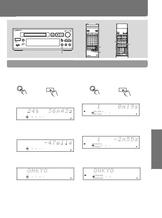
Changing the display mode
When the MD recorder is stopped
Pressing the DISPLAY button changes the display in the following sequence:
Remote controller
DISPLAY
DISPLAY
Total number of tracks on the MD and its total playing time
DIGITAL IN 1
L |
|
|
|
|
|
1 |
2 |
3 |
4 |
5 |
|
40 |
20 |
10 |
6 |
2 |
0 |
6 |
7 |
8 |
9 |
10 |
|
R |
|
|
|
|
|
11 |
12 |
13 |
14 |
15 |
15 |
↓
Time remaining for recording on the MD (Not displayed if it is a premastered MD)
DISC
DIGITAL IN 1
L |
|
|
|
|
|
1 |
2 |
3 |
4 |
5 |
|
40 |
20 |
10 |
6 |
2 |
0 |
6 |
7 |
8 |
9 |
10 |
|
R |
|
|
|
|
|
11 |
12 |
13 |
14 |
15 |
15 |
↓
Disc name ("No Name" when not set)
DISC
DIGITAL IN 1
L |
|
|
|
|
|
1 |
2 |
3 |
4 |
5 |
|
40 |
20 |
10 |
6 |
2 |
0 |
6 |
7 |
8 |
9 |
10 |
|
R |
|
|
|
|
|
11 |
12 |
13 |
14 |
15 |
15 |
When an MD is playing
Pressing the DISPLAY button changes the display
in the following sequence:
Remote controller
DISPLAY
DISPLAY
Playing track number and elapsed playing time
TRACK
DIGITAL IN 1
L |
|
|
|
|
|
1 |
2 |
3 |
4 |
5 |
|
40 |
20 |
10 |
6 |
2 |
0 |
6 |
7 |
8 |
9 |
10 |
|
R |
|
|
|
|
|
11 |
12 |
13 |
14 |
15 |
15 |
↓
Playing track number and remaining playing time
TRACK
DIGITAL IN 1
L |
|
|
|
|
|
1 |
2 |
3 |
4 |
5 |
|
40 |
20 |
10 |
6 |
2 |
0 |
6 |
7 |
8 |
9 |
10 |
|
R |
|
|
|
|
|
11 |
12 |
13 |
14 |
15 |
15 |
↓
Track name (Track number with "No Name" when not set)
TRACK
DIGITAL IN 1
L |
|
|
|
|
|
1 |
2 |
3 |
4 |
5 |
|
40 |
20 |
10 |
6 |
2 |
0 |
6 |
7 |
8 |
9 |
10 |
|
R |
|
|
|
|
|
11 |
12 |
13 |
14 |
15 |
15 |
If the track name is too long to display
You can scroll the track name by pressing the SCROLL button on the remote controller.
Press the SCROLL button when the track name is scrolling to stop the scrolling of the track name; press the SCROLL button again to resume the scrolling of the track name.
To exit the display scroll mode, press the CLEAR button on the remote controller.
Using Before
Connections
Operations
Information Other
(Continued to the next page) 15

Normal play (continued) |
|
|
|
|
|
|
|
|
|
|
qAMCSw |
RC-409MD(supplied) |
RC-398S (supplied with |
||||||
|
|
|
|
|
|
|
|
A-905X) |
|
|
|
POWER |
|
|
|
EJECT |
|
|
|
MINDISC RECODER |
AMCS |
|
|
|
|
|
|
|
|
|
PUSH TO ENTER |
|
PLAY MODE |
|
|
|
|
POWER |
INPUT SELECTOR |
|
|
CONTINUE RANDOM |
MEMORY |
|
|
|
|
|
|
|
|
A |
B |
C |
D |
E |
|
|
|
|
DISC LOADING MECHANISM0 |
1 |
2 |
3 |
4 |
5 |
|
|
|
|
|
F |
G |
H |
I |
J |
|
|
|
STANDBY/ON |
|
6 |
7 |
8 |
9 |
10 |
|
|
|
CD |
|
K |
L |
M |
N |
O |
|
|
|
DUBBING |
REC |
11 |
12 |
13 |
14 |
15 |
Number |
|
|
|
P |
Q |
R |
S |
T |
|
|
||
|
|
U |
V |
W |
X |
Y |
|
|
|
|
|
16 |
17 |
18 |
19 |
20 |
button |
|
|
MO ST D1 D2 |
DISPLAY EDIT/NO YES |
>25 |
|
|
|
|
|
|
|
STANDBY |
|
21 |
22 |
23 |
24 |
25 |
|
|
|
INPUT |
|
Z |
|
|
. |
, |
|
|
q,w |
|
|
|
|
|
|
|
|||
|
|
|
|
|
|
|
|
|
|
ANALOG |
|
|
|
|
|
|
|
|
Number |
|
MD-105X |
|
|
SCROLL |
DISPLAY NAME |
q,w |
|
||
|
|
|
|
|
|
|
|
button |
|
|
|
REMOTE CONTROLLER RC-409MD |
|
|
|
|
|||
Selecting the track to play using the number buttons
Press the number button on the remote controller to select the track you want to play.
(RC-409MD) (RC-398S)
|
|
|
|
|
|
|
|
|
|
1 |
C D / M D |
3 |
|
|
|
|
|
|
|
|
|
|
2 |
||
|
1 |
|
2 |
|
3 |
|
4 |
|
5 |
|
|
|
|
F |
|
G |
H |
|
I |
|
J |
|
|
|
|
|
|
|
|
|
|
|
|
|
|
|
|
|
|
6 |
|
7 |
|
8 |
|
9 |
|
10 |
4 |
5 |
6 |
|
K |
|
L |
M |
|
N |
|
O |
|
|
|
|
|
|
|
|
|
|
|
|
|
|
|
|
|
|
11 |
|
12 |
|
13 |
|
14 |
|
15 |
|
|
|
|
P |
|
Q |
R |
|
S |
|
T |
7 |
8 |
9 |
|
|
|
|
|
|
|
|
|
|
|
|
|
|
|
16 |
|
17 |
|
18 |
|
19 |
|
20 |
|
|
|
|
U |
|
V |
W |
|
X |
|
Y |
-- / - - - |
10 / 0 |
|
|
|
|
|
|
|
|
|
|
|
|
|
||
|
|
|
|
|
|
|
|
|
|
|
|
|
|
21 |
|
22 |
|
23 |
|
24 |
|
25 |
|
|
|
|
Z |
|
|
|
|
|
. |
|
, |
|
|
|
|
|
|
|
|
|
|
|
|
|
|
|
|
|
>25 |
|
|
|
|
|
|
|
|
|
|
|
/ |
|
|
|
|
|
|
|
|
|
|
|
|
|
|
|
|
|
|
|
|
|
|
|
||
|
|
TRACK |
|
|
|
|
|
|
|
|
||
|
DIGITAL IN 1 |
|
|
|
|
|
|
|
|
|||
|
|
|
L |
40 |
20 |
10 |
6 |
2 |
0 |
|
|
|
|
|
|
R |
|
|
|||||||
|
|
|
|
|
|
|
|
|
|
15 |
||
|
|
|
|
|
|
|
|
|
|
|
|
|
To select a track numbered 26 or above using RC-409MD
Press the [>25] button first. Set a value for the 10th place and then the 1st place using the number buttons in this order. ("0" can be entered by pressing the [10] button.)
Ex. To select the 30th track: [>25] + [3] + [10]
To select the 100th track:
[>25] + [>25] + [1] + [10] + [10]
To select a track numbered 11 or above using RC-398S
Press the [--/---] button first. Set a value for the 10th place and then the 1st place using the number buttons in this order. ("0" can be entered by pressing the [10/0] button.)
Ex. To select the 30th track: [--/---] + [3] + [10/0]
To select the 100th track:
[--/---] + [--/---] + [1] + [10/0] + [10/0]
Changing the playing track using the AMCS
During play, you can change the track that is playing by turning the AMCS knob (or by pressing the q and w buttons on the remote controller).
If the MD recorder is stopped, turn the AMCS knob to select the track number you wish to play, and press that knob (with the remote controller, use the q or w button to select the track, then press the s button.)
 AMCS
AMCS 
( PUSH TO ENTER )
Remote controller
q w
To play the next track or a later track
Turn the AMCS knob clockwise (or press the w button on the remote controller several times) until the desired track is located.
To start play again from the beginning of the track that is currently playing or to play the previous track or an earlier track
Turn the AMCS knob counterclockwise (or press the q button on the remote controller several times) until the desired track is located. In the Memory play mode (see page 19), turning the AMCS knob (or pressing the w or q button) selects the track in the stored sequence.
16
Normal play (continued)
RC-409MD (supplied)
|
|
|
|
POWER |
|
|
|
EJECT |
|
MINDISC RECODER |
|
AMCS |
|
|
|
|
|
|
|
|
PUSH TO ENTER |
|
PLAY MODE |
|
|
|
|
|
|
|
CONTINUE RANDOM |
MEMORY |
|
|
|
|
|
|
|
A |
B |
C |
D |
E |
|
|
DISC LOADING MECHANISM0 |
d,f |
1 |
2 |
3 |
4 |
5 |
|
|
|
F |
G |
H |
I |
J |
|
|
|
|
6 |
7 |
8 |
9 |
10 |
|
STANDBY/ON |
CD |
|
11K |
12L |
13M |
14N |
15O |
|
|
DUBBING |
REC |
|
P |
Q |
R |
S |
T |
|
|
|
|
16 |
17 |
18 |
19 |
20 |
|
|
|
|
U |
V |
W |
X |
Y |
STANDBY |
|
|
|
21 |
22 |
23 |
24 |
25 |
|
|
|
Z |
|
|
. |
, |
|
INPUT |
DISPLAY EDIT/NO |
YES |
>25 |
MO ST D1 D2 |
|
|
|
ANALOG |
|
|
M SCAN |
MD-105X |
SCROLL DISPLAY NAME |
d,f |
REMOTE CONTROLLER RC-409MD
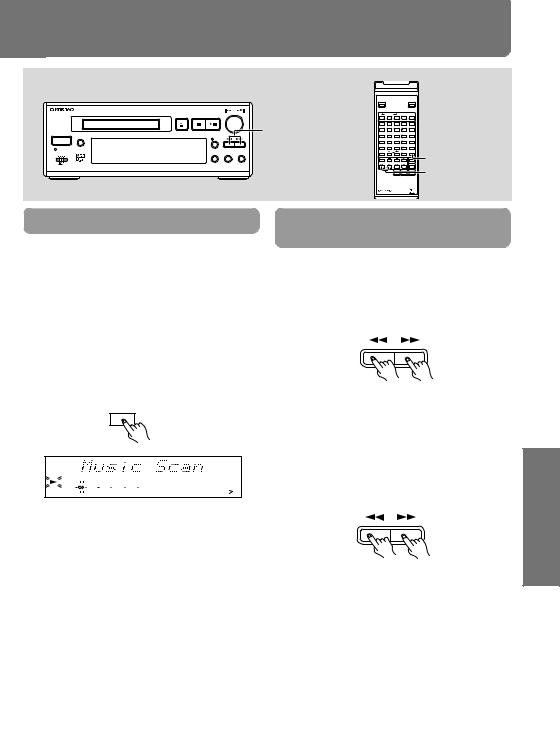
Music Scan
The following operation is possible only when using the supplied remote controller (RC-409MD).
Pressing the M.SCAN button plays the beginning (8 seconds) of each track on the disc in sequence whether the MD recorder is either playing or stopped.
•The s indicator flashes during Music Scan.
•You can press the s or M.SCAN button on the remote controller when the beginning of the desired track is playing to start playing
from that track.
M.SCAN
DIGITAL IN 1
L |
|
|
|
|
|
1 |
2 |
3 |
4 |
5 |
|
40 |
20 |
10 |
6 |
2 |
0 |
6 |
7 |
8 |
9 |
10 |
|
R |
|
|
|
|
|
11 |
12 |
13 |
14 |
15 |
15 |
Searching for a part to play (Search play)
Searching for a part to play by sound (at play)
During play, hold down the d or f button and release it when the part you want to hear is playing.
Searching for a part to play by using displayed time (at pause, high-speed search)
When playing is temporarily stopped (paused), keep pressing the d or f button and release it when the playing time of the part you want to hear is displayed.
•Press the n button (or the s button on the remote controller) to start playing from that part.
•"Over" in the display indicates that the end of the last track is reached.
Using Before
Connections
Operations
Information Other
(Continued to the next page) 17
 Loading...