


 Loading...
AV RECEIVER
HT-RC460
Instruction Manual
Contents |
|
Safety Information and Introduction |
............2 |
Table of Contents........................................... |
5 |
Connections ................................................. |
11 |
Turning On & Basic Operations.................. |
19 |
Advanced Operations .................................. |
43 |
Controlling Other Components................... |
66 |
Appendix....................................................... |
73 |
Internet Radio Guide |
|
Remote Control Codes |
|
En
WARNING:
TO REDUCE THE RISK OF FIRE OR ELECTRIC SHOCK, DO NOT EXPOSE THIS APPARATUS TO RAIN OR MOISTURE.
CAUTION:
TO REDUCE THE RISK OF ELECTRIC SHOCK, DO NOT REMOVE COVER (OR BACK). NO USER-SERVICEABLE PARTS INSIDE. REFER SERVICING TO QUALIFIED SERVICE PERSONNEL.
WARNING |
|
AVIS |
RISK OF ELECTRIC SHOCK |
|
RISQUE DE CHOC ELECTRIQUE |
DO NOT OPEN |
|
NE PAS OUVRIR |
|
|
|
The lightning flash with arrowhead symbol, within an equilateral triangle, is intended to alert the user to the presence of uninsulated “dangerous voltage” within the product’s enclosure that may be of sufficient
magnitude to constitute a risk of electric shock to persons.
The exclamation point within an equilateral triangle is intended to alert the user to the presence of important operating and maintenance (servicing) instructions in the literature accompanying the appliance.
Important Safety Instructions
1.Read these instructions.
2.Keep these instructions.
3.Heed all warnings.
4.Follow all instructions.
5.Do not use this apparatus near water.
6.Clean only with dry cloth.
7.Do not block any ventilation openings. Install in accordance with the manufacturer’s instructions.
8.Do not install near any heat sources such as radiators, heat registers, stoves, or other apparatus (including amplifiers) that produce heat.
9.Do not defeat the safety purpose of the polarized or grounding-type plug. A polarized plug has two blades with one wider than the other. A grounding type plug has two blades and a third grounding prong. The wide blade or the third prong are provided for your safety. If the provided plug does not fit into your outlet, consult an electrician for replacement of the obsolete outlet.
10.Protect the power cord from being walked on or pinched particularly at plugs, convenience receptacles, and the point where they exit from the apparatus.
11.Only use attachments/accessories specified by the
manufacturer.
12. Use only with the cart, stand, tripod, bracket, or table
specified by the manufacturer, or sold with the apparatus.
When a cart is used, use caution when moving the
cart/apparatus combination to
S3125A
avoid injury from tip-over.
13.Unplug this apparatus during lightning storms or when unused for long periods of time.
14.Refer all servicing to qualified service personnel. Servicing is required when the apparatus has been damaged in any way, such as power-supply cord or plug is damaged, liquid has been spilled or objects have fallen into the apparatus, the apparatus has been exposed to rain or moisture, does not operate normally, or has been dropped.
15.Damage Requiring Service
Unplug the apparatus from the wall outlet and refer servicing to qualified service personnel under the following conditions:
A.When the power-supply cord or plug is damaged,
B.If liquid has been spilled, or objects have fallen into the apparatus,
C.If the apparatus has been exposed to rain or water,
Safety Information and Introduction
D.If the apparatus does not operate normally by following the operating instructions. Adjust only those controls that are covered by the operating instructions as an improper adjustment of other controls may result in damage and will often require extensive work by a qualified technician to restore the apparatus to its normal operation,
E.If the apparatus has been dropped or damaged in any way, and
F.When the apparatus exhibits a distinct change in performance this indicates a need for service.
16.Object and Liquid Entry
Never push objects of any kind into the apparatus through openings as they may touch dangerous voltage points or short-out parts that could result in a fire or electric shock.
The apparatus shall not be exposed to dripping or splashing and no objects filled with liquids, such as vases shall be placed on the apparatus.
Don’t put candles or other burning objects on top of this unit.
17.Batteries
Always consider the environmental issues and follow local regulations when disposing of batteries.
18.If you install the apparatus in a built-in installation, such as a bookcase or rack, ensure that there is adequate ventilation.
Leave 20 cm (8") of free space at the top and sides and 10 cm (4") at the rear. The rear edge of the shelf or board above the apparatus shall be set 10 cm (4") away from the rear panel or wall, creating a flue-like gap for warm air to escape.
En-2

Precautions
1.Recording Copyright—Unless it’s for personal use only, recording copyrighted material is illegal without the permission of the copyright holder.
2.AC Fuse—The AC fuse inside the unit is not userserviceable. If you cannot turn on the unit, contact your Onkyo dealer.
3.Care—Occasionally you should dust the unit all over with a soft cloth. For stubborn stains, use a soft cloth dampened with a weak solution of mild detergent and water. Dry the unit immediately afterwards with a clean cloth. Don’t use abrasive cloths, thinners, alcohol, or other chemical solvents, because they may damage the finish or remove the panel lettering.
4.Power WARNING
BEFORE PLUGGING IN THE UNIT FOR THE FIRST TIME, READ THE FOLLOWING SECTION CAREFULLY.
AC outlet voltages vary from country to country. Make sure that the voltage in your area meets the voltage requirements printed on the unit’s rear panel (e.g., AC 230 V, 50 Hz or AC 120 V, 60 Hz).
The power cord plug is used to disconnect this unit from the AC power source. Make sure that the plug is readily operable (easily accessible) at all times.
For models with [POWER] button, or with both [POWER] and [ON/STANDBY] buttons: Pressing the [POWER] button to select OFF mode
does not fully disconnect from the mains. If you do not intend to use the unit for an extended period, remove the power cord from the AC outlet.
For models with [ON/STANDBY] button only: Pressing the [ON/STANDBY] button to select Standby mode does not fully disconnect from the mains. If you do not intend to use the unit for an extended period, remove the power cord from the AC outlet.
5.Preventing Hearing Loss Caution
Excessive sound pressure from earphones and headphones can cause hearing loss.
6.Batteries and Heat Exposure Warning
Batteries (battery pack or batteries installed) shall not be exposed to excessive heat as sunshine, fire or the like.
7.Never Touch this Unit with Wet Hands—Never handle this unit or its power cord while your hands are wet or damp. If water or any other liquid gets inside this unit, have it checked by your Onkyo dealer.
8.Handling Notes
•If you need to transport this unit, use the original packaging to pack it how it was when you originally bought it.
•Do not leave rubber or plastic items on this unit for a long time, because they may leave marks on the case.
•This unit’s top and rear panels may get warm after prolonged use. This is normal.
•If you do not use this unit for a long time, it may not work properly the next time you turn it on, so be sure to use it occasionally.
For U.S. models
FCC Information for User CAUTION:
The user changes or modifications not expressly approved by the party responsible for compliance could void the user’s authority to operate the equipment.
NOTE:
This equipment has been tested and found to comply with the limits for a Class B digital device, pursuant to Part 15 of the FCC Rules. These limits are designed to provide reasonable protection against harmful interference in a residential installation.
En-3
Safety Information and Introduction
This equipment generates, uses and can radiate radio frequency energy and, if not installed and used in accordance with the instructions, may cause harmful interference to radio communications. However, there is no guarantee that interference will not occur in a particular installation. If this equipment does cause harmful interference to radio or television reception, which can be determined by turning the equipment off and on, the user is encouraged to try to correct the interference by one or more of the following measures:
•Reorient or relocate the receiving antenna.
•Increase the separation between the equipment and receiver.
•Connect the equipment into an outlet on a circuit different from that to which the receiver is connected.
•Consult the dealer or an experienced radio/TV technician for help.
For Canadian Models
NOTE: THIS CLASS B DIGITAL APPARATUS COMPLIES WITH CANADIAN ICES-003.
For models having a power cord with a polarized plug: CAUTION: TO PREVENT ELECTRIC SHOCK, MATCH WIDE BLADE OF PLUG TO WIDE SLOT, FULLY INSERT.
Modèle pour les Canadien
REMARQUE: CET APPAREIL NUMÉRIQUE DE LA CLASSE B EST CONFORME À LA NORME NMB-003 DU CANADA.
Sur les modèles dont la fiche est polarisée: ATTENTION: POUR ÉVITER LES CHOCS ÉLECTRIQUES, INTRODUIRE LA LAME LA PLUS LARGE DE LA FICHE DANS LA BORNE CORRESPONDANTE DE LA PRISE ET POUSSER JUSQU’AU FOND.
Supplied Accessories
Make sure you have the following accessories:
Indoor FM antenna ( page 18)
AM loop antenna ( page 18)
Speaker cable labels ( page 12)
Speaker setup microphone ( page 33)
Remote controller (RC-834M) and two batteries (AA/R6)
Quick Start Guide
*In catalogs and on packaging, the letter at the end of the product name indicates the color. Specifications and operations are the same regardless of color.
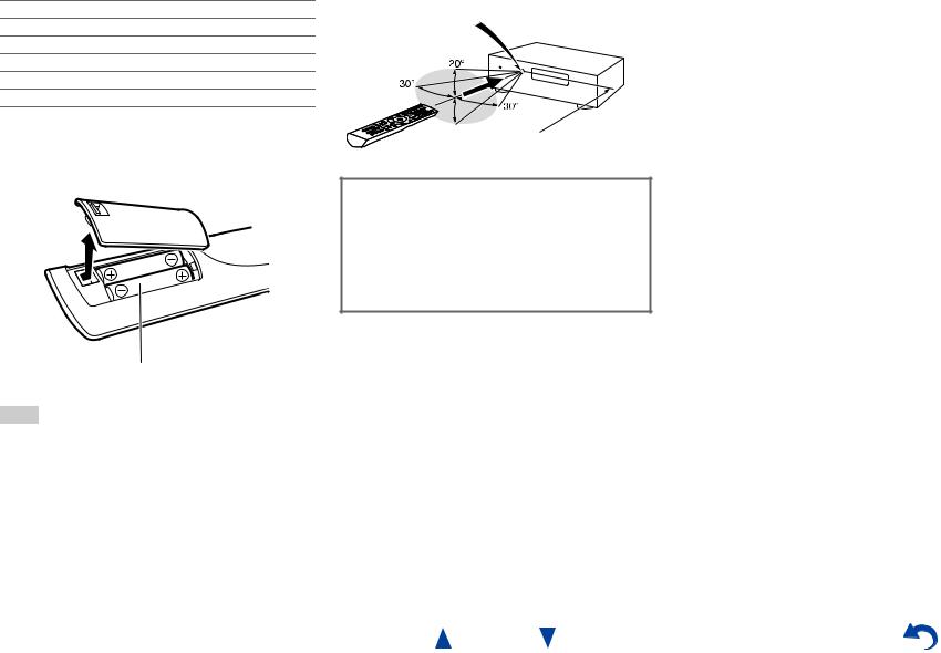
■Installing the batteries
Batteries (AA/R6)
Note
•If the remote controller doesn’t work reliably, try replacing the batteries.
•Don’t mix new and old batteries or different types of batteries.
•If you intend not to use the remote controller for a long time, remove the batteries to prevent damage from leakage or corrosion.
•Remove expired batteries as soon as possible to prevent damage from leakage or corrosion.
Safety Information and Introduction
■Aiming the remote controller
To use the remote controller, point it at the AV receiver’s remote control sensor, as shown below.
Remote control sensor
AV receiver
 Approx. 16 ft. (5 m)
Thank you for purchasing an Onkyo AV Receiver. Please read this manual thoroughly before making connections and plugging in the unit.
Following the instructions in this manual will enable you to obtain optimum performance and listening enjoyment from your new AV Receiver. Please retain this manual for future reference.
En-4
Table of Contents |
|
Safety Information and Introduction |
|
Important Safety Instructions ...................................... |
2 |
Precautions ................................................................... |
3 |
Supplied Accessories................................................... |
4 |
Table of Contents.......................................................... |
5 |
Features ......................................................................... |
6 |
Front & Rear Panels...................................................... |
7 |
Front Panel.................................................................. |
7 |
Display ........................................................................ |
8 |
Rear Panel .................................................................. |
9 |
Remote Controller....................................................... |
10 |
Controlling the AV Receiver...................................... |
10 |
Connections |
|
Connecting the AV Receiver...................................... |
11 |
Connecting Your Speakers ....................................... |
11 |
About AV Connections.............................................. |
14 |
Connecting Components with HDMI ......................... |
15 |
Connecting Your Components.................................. |
16 |
Connecting Onkyo RI Components........................... |
17 |
Connecting the Antennas.......................................... |
18 |
Connecting the Power Cord ...................................... |
18 |
Turning On & Basic Operations |
|
Turning On/Off the AV Receiver ................................ |
19 |
Turning On ................................................................ |
19 |
Turning Off ................................................................ |
19 |
Initial Setup.................................................................. |
20 |
Selecting the Language |
|
for the Onscreen Setup Menus............................... |
20 |
Audyssey 2EQ: Auto Setup....................................... |
20 |
Source Connection.................................................... |
21 |
Remote Mode Setup ................................................. |
21 |
Network Connection.................................................. |
21 |
Terminating the Initial Setup ..................................... |
21 |
Playback ...................................................................... |
22 |
Playing the Connected Component .......................... |
22 |
Controlling Contents of USB or Network Devices..... |
23 |
Understanding Icons on the Display ......................... |
24 |
Playing an iPod/iPhone via USB............................... |
24 |
Playing a USB Device............................................... |
25 |
Listening to vTuner Internet Radio............................ |
26 |
Registering Other Internet Radio .............................. |
27 |
Changing the Icon Layout |
|
on the Network Service Screen.............................. |
27 |
Playing Music Files on a Server ............................... |
28 |
Remote Playback...................................................... |
29 |
Listening to AM/FM Radio ........................................ |
30 |
Using Basic Functions............................................... |
32 |
Using the Automatic Speaker Setup......................... |
32 |
Using the Listening Modes ....................................... |
35 |
Using the Home Menu .............................................. |
40 |
Using the Sleep Timer .............................................. |
41 |
Setting the Display Brightness.................................. |
41 |
Displaying Source Information.................................. |
41 |
Changing the Input Display....................................... |
41 |
Using the Music Optimizer........................................ |
42 |
Muting the AV Receiver ............................................ |
42 |
Using Headphones ................................................... |
42 |
Advanced Operations |
|
On-screen Setup......................................................... |
43 |
Using the Quick Setup .............................................. |
43 |
Using the Audio Settings of Quick Setup.................. |
44 |
Using the Setup Menu (HOME) ................................ |
46 |
About the HYBRID STANDBY indicator ................... |
47 |
Setup menu items..................................................... |
47 |
Input/Output Assign .................................................. |
48 |
Speaker Setup .......................................................... |
50 |
Audio Adjust.............................................................. |
52 |
Source Setup ............................................................ |
53 |
Listening Mode Preset .............................................. |
58 |
Miscellaneous ........................................................... |
59 |
Hardware Setup........................................................ |
59 |
Remote Controller Setup .......................................... |
63 |
Lock Setup................................................................ |
63 |
Zone 2 .......................................................................... |
64 |
Making Zone 2 Connections ..................................... |
64 |
Controlling Zone 2 Components ............................... |
65 |
Safety Information and Introduction |
|
Controlling Other Components |
|
iPod/iPhone Playback via Onkyo Dock .................... |
66 |
Using the Onkyo Dock.............................................. |
66 |
Controlling Your iPod/iPhone ................................... |
67 |
Controlling Other Components................................. |
68 |
Preprogrammed Remote Control Codes .................. |
68 |
Looking up for Remote Control Codes ..................... |
68 |
Entering Remote Control Codes............................... |
69 |
Remapping Colored Buttons .................................... |
69 |
Remote Control Codes |
|
for Onkyo Components Connected via RI ............. |
70 |
Resetting the REMOTE MODE Buttons ................... |
70 |
Resetting the Remote Controller .............................. |
70 |
Controlling Other Components................................. |
70 |
Appendix |
|
Troubleshooting ......................................................... |
73 |
Firmware Update ........................................................ |
79 |
Connection Tips and Video Signal Path .................. |
83 |
Using an RIHD-compatible TV, Player, |
|
or Recorder .............................................................. |
86 |
About HDMI................................................................. |
88 |
Network/USB Features............................................... |
89 |
License and Trademark Information ........................ |
92 |
Specifications ............................................................. |
93 |
To reset the AV receiver to its factory defaults, turn it on and, while holding down CBL/SAT, press
8ON/STANDBY ( page 73).
En-5

Features
Amplifier
•80 Watts/Channel @ 8 ohms (FTC)
•Optimum Gain Volume Circuitry
•H.C.P.S. (High Current Power Supply) Massive High Power Transformer
Processing
•Incorporates Qdeo™ technology for HDMI Video Upscaling (to 4K Compatible)
•HDMI (Audio Return Channel, 3D, DeepColor, x.v.Color, Lip Sync, DTS-HD Master Audio, DTS-HD High Resolution Audio, Dolby TrueHD, Dolby Digital Plus, DSD and Multi-CH PCM)
•Dolby Pro Logic IIz
•Non-Scaling Configuration
•A-Form Listening Mode Memory
•Direct Mode
•Music Optimizer for Compressed Digital Music files
•192 kHz/24-bit D/A Converters
•Powerful and Highly Accurate 32-bit Processing DSP
•Jitter Cleaning Circuit Technology
Safety Information and Introduction
Connections
•8 HDMI Inputs (1 on front panel) and 2 Outputs
•Onkyo pfor System Control
•4 Digital Inputs (2 Optical/2 Coaxial)
•Component Video Switching (1 Input/1 Output)
•Banana Plug-Compatible Speaker Posts
•Powered Zone 2
•Bi-Amping Capability for FL/FR with SBL/SBR
•Internet Radio Connectivity
•Network Capability for Streaming Audio Files
•2 USB Inputs (Front/Rear) for Memory Devices and iPod®/iPhone® models (Enables Display of Album Artwork)
*Only the front-panel USB input is compatible with iPod/iPhone.
•MHL-Enabled AUX Front Input
Miscellaneous
•40 FM/AM Presets
•Audyssey 2EQ® to correct room acoustic problems
•Audyssey Dynamic EQ® for loudness correction
•Audyssey Dynamic Volume® to maintain optimal listening level and dynamic range
•Crossover Adjustment (40/50/60/70/80/90/100/120/150/200 Hz)
•A/V Sync Control Function (up to 800 ms)
•Auto Standby Function
•On-Screen Display via HDMI
•Preprogrammed u-Compatible Remote
En-6
Safety Information and Introduction
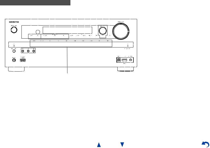
Front & Rear Panels
Front Panel
a |
|
|
|
|
|
|
|
b c d e |
|
|
|
|
f g h i j k l |
m |
|
||||||||||||||||||||||||||||||||||||||||||||||||||||||||||||||||||||
|
|
|
|
|
|
|
|
|
|
|
|
|
|
|
|
|
|
|
|
|
|
|
|
|
|
|
|
|
|
|
|
|
|
|
|
|
|
|
|
|
|
|
|
|
|
|
|
|
|
|
|
|
|
|
|
|
|
|
|
|
|
|
|
|
|
|
|
|
|
|
|
|
|
|
|
|
|
|
|
|
|
|
|
|
|
|
|
|
|
|
|
|
|
|
|
|
|
|
|
|
|
|
|
|
|
|
|
|
|
|
|
|
|
|
|
|
|
|
|
|
|
|
|
|
|
|
|
|
|
|
|
|
|
|
|
|
|
|
|
|
|
|
|
|
|
|
|
|
|
|
|
|
|
|
|
|
|
|
|
|
|
|
|
|
|
|
|
|
|
|
|
|
|
|
|
|
|
|
|
|
|
|
|
|
|
|
|
|
|
|
|
|
|
|
|
|
|
|
|
|
|
|
|
|
|
|
|
|
|
|
|
|
|
|
|
|
|
|
|
|
|
|
|
|
|
|
|
|
|
|
|
|
|
|
|
|
|
|
|
|
|
|
|
|
|
|
|
|
|
|
|
|
|
|
|
|
|
|
|
|
|
|
|
|
|
|
|
|
|
|
|
|
|
|
|
|
|
|
|
|
|
|
|
|
|
|
|
|
|
|
|
|
|
|
|
|
|
|
|
|
|
|
|
|
|
|
|
|
|
|
|
|
|
|
|
|
|
|
|
|
|
|
|
|
|
|
|
|
|
|
|
|
|
|
|
|
|
|
|
|
|
|
|
|
|
|
|
|
|
|
|
|
|
|
|
|
|
|
|
|
|
|
|
|
|
|
|
|
|
|
|
|
|
|
|
|
|
|
|
|
|
|
|
|
|
|
|
|
|
|
|
|
|
|
|
|
|
|
|
|
|
|
|
|
|
|
|
|
|
|
|
|
|
|
|
|
|
|
|
|
|
|
|
|
|
|
|
|
|
|
|
|
|
|
|
|
|
|
|
|
|
|
|
|
|
|
|
|
|
|
|
|
|
|
|
|
|
|
|
|
|
|
|
|
|
|
|
|
|
|
|
|
|
|
|
|
|
|
|
|
|
|
|
|
|
|
|
|
|
|
|
|
|
|
|
|
|
|
|
|
|
|
|
|
|
|
|
|
|
|
|
|
|
|
|
|
|
|
|
|
|
|
|
|
|
|
|
|
|
|
|
|
|
|
|
|
|
|
|
|
|
|
|
|
|
|
|
|
|
|
|
|
|
|
|
|
|
|
|
|
|
|
|
|
|
|
|
|
|
|
|
|
|
|
|
|
|
|
|
|
|
|
|
|
|
|
|
|
|
|
|
|
|
|
|
|
|
|
|
|
|
|
|
|
|
|
|
|
|
|
|
|
|
|
|
|
|
|
|
|
|
|
|
|
|
|
|
|
|
|
|
|
|
|
|
|
|
|
|
|
|
|
|
|
|
|
|
|
|
|
|
|
|
|
|
|
|
|
|
|
|
|
|
|
|
|
|
|
|
|
|
|
|
|
|
|
|
|
|
|
|
|
|
|
|
|
|
|
|
|
|
|
|
|
|
|
|
|
|
|
|
|
|
|
|
|
|
|
|
|
|
|
|
|
|
|
|
|
|
|
|
|
|
|
|
|
|
|
|
|
|
|
|
|
|
|
|
|
|
|
|
|
|
|
|
|
|
|
|
|
|
|
|
|
|
|
|
|
|
|
|
|
|
|
|
|
|
|
|
|
|
|
|
|
|
|
|
|
|
|
|
|
|
|
|
|
|
|
|
|
|
|
|
|
|
|
|
|
|
|
|
|
|
|
|
|
|
|
|
|
|
|
|
|
|
|
|
|
|
|
|
|
|
|
|
|
|
|
|
|
|
|
|
|
|
|
|
|
|
|
|
|
|
|
|
|
|
|
|
|
|
|
|
|
|
|
|
|
|
|
|
|
|
|
|
|
|
|
|
|
|
|
|
|
|
|
|
|
|
|
|
|
|
|
|
|
|
|
|
|
|
|
|
|
|
|
|
|
|
|
|
|
|
|
|
|
|
|
|
|
|
|
|
|
|
|
|
|
|
|
|
|
|
|
|
|
|
|
|
|
|
|
|
|
|
|
|
|
|
|
|
|
|
|
|
|
|
|
|
|
|
|
|
|
|
|
|
|
|
|
|
|
|
|
|
|
|
|
|
|
|
|
|
|
|
|
|
|
|
|
|
|
|
|
|
|
|
|
|
|
|
|
|
|
|
|
|
|
|
|
|
|
|
|
|
|
|
|
|
|
|
|
|
|
|
|
|
|
|
|
|
|
|
|
|
|
|
|
|
|
|
|
|
|
|
|
|
|
|
|
|
|
|
|
|
|
|
|
|
|
|
|
|
|
|
|
|
|
|
|
|
|
|
|
|
|
|
|
|
|
|
|
|
|
|
|
|
|
|
|
|
|
|
|
|
|
|
|
|
|
|
|
|
|
|
|
|
|
|
|
|
|
|
|
|
|
|
|
|
|
|
|
|
|
|
|
|
|
|
|
|
|
|
|
|
|
|
|
|
|
|
|
|
|
|
|
|
|
|
|
|
|
|
|
|
|
|
|
|
|
|
|
|
|
|
|
|
|
|
|
|
|
|
|
|
|
|
|
|
|
|
|
|
|
|
n o p q |
r |
For detailed information, see the pages in parentheses.
a 8ON/STANDBY button (19)
b ZONE 2, OFF buttons (65)
c Remote control sensor (4)
d Display (8)
e LISTENING MODE buttons (35)
f DIMMER button (41)
g MEMORY button (31)
h TUNING MODE button (30)
i DISPLAY button (41)
j SETUP button (46)
s t u v
k TUNING q/w(30), PRESET e/r(31), cursor and |
v HYBRID STANDBY indicator (47) |
ENTER buttons |
|
l RETURN button |
|
m MASTER VOLUME control (22) |
|
n MUSIC OPTIMIZER button and indicator (42, 45) |
|
o PHONES jack (42) |
|
p AUX INPUT HDMI/MHL jack (15) |
|
q TONE and Tone Level buttons (44) |
|
r Input selector buttons (22) |
|
s VIDEO jack (16) |
|
t USB port (16) |
|
u SETUP MIC jack (33) |
|
En-7
Safety Information and Introduction
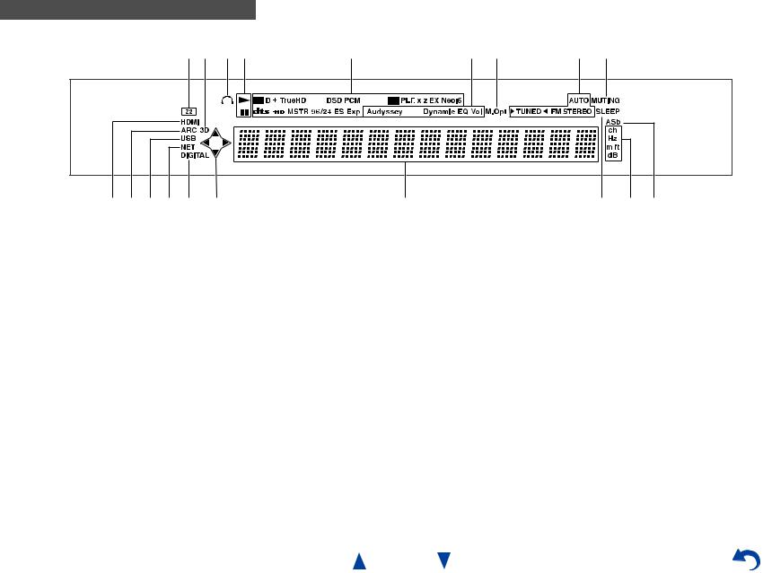
Display
ab cd |
e |
f g |
h i |
j k l m j d |
n |
|
o p q |
For detailed information, see the pages in parentheses.
a Z2 (Zone 2) indicator (65)
b3D indicator
This lights when a 3D input signal is detected.
c Headphone indicator (42)
d 1, 3and cursor indicators (24)
e Listening mode and format indicators (35)
fAudyssey indicator (32, 53) Dynamic EQ indicator (54) Dynamic Vol indicator (54)
g M.Opt indicator (42, 45)
hTuning indicators AUTO indicator (30) TUNED indicator (30)
FM STEREO indicator (30)
i MUTING indicator (42)
jInput indicators (84) HDMI indicator (60) DIGITAL indicator
k ARC indicator (61) l USB indicator (24, 25)
m NET indicator (26 to 29, 62) n Message area
o SLEEP indicator (41)
pChannel/Unit indicators ch indicator
Hz indicator m/ft indicator dB indicator
q ASb indicator (61)
En-8
Safety Information and Introduction
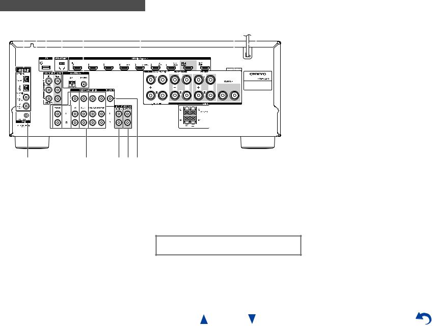
Rear Panel
a bc d e |
|
|
|
|
|
|
f |
|
|
|
|
|
|
g h |
|||||||||||||||||||||||||||||||||||||||||||||
|
|
|
|
|
|
|
|
|
|
|
|
|
|
|
|
|
|
|
|
|
|
|
|
|
|
|
|
|
|
|
|
|
|
|
|
|
|
|
|
|
|
|
|
|
|
|
|
|
|
|
|
|
|
|
|
|
|
|
|
|
|
|
|
|
|
|
|
|
|
|
|
|
|
|
|
|
|
|
|
|
|
|
|
|
|
|
|
|
|
|
|
|
|
|
|
|
|
|
|
|
|
|
|
|
|
|
|
|
|
|
|
|
|
|
|
|
|
|
|
|
|
|
|
|
|
|
|
|
|
|
|
|
|
|
|
|
|
|
|
|
|
|
|
|
|
|
|
|
|
|
|
|
|
|
|
|
|
|
|
|
|
|
|
|
|
|
|
|
|
|
|
|
|
|
|
|
|
|
|
|
|
|
|
|
|
|
|
|
|
|
|
|
|
|
|
|
|
|
|
|
|
|
|
|
|
|
|
|
|
|
|
|
|
|
|
|
|
|
|
|
|
|
|
|
|
|
|
|
|
|
|
|
|
|
|
|
|
|
|
|
|
|
|
|
|
|
|
|
|
|
|
|
|
|
|
|
|
|
|
|
|
|
|
|
|
|
|
|
|
|
|
|
|
|
|
|
|
|
|
|
|
|
|
|
|
|
|
|
|
|
|
|
|
|
|
|
|
|
|
|
|
|
|
|
|
|
|
|
|
|
|
|
|
|
|
|
|
|
|
|
|
|
|
|
|
|
|
|
|
|
|
|
|
|
|
|
|
|
|
|
|
|
|
|
|
|
|
|
|
|
|
|
|
|
|
|
|
|
|
|
|
|
|
|
|
|
|
|
|
|
|
|
|
|
|
|
|
|
|
|
|
|
|
|
|
|
|
|
|
|
|
|
|
|
|
|
|
|
|
|
|
|
|
|
|
|
|
|
|
|
|
|
|
|
|
|
|
|
|
|
|
|
|
|
|
|
|
|
|
|
|
|
|
|
|
|
|
|
|
|
|
|
|
|
|
|
|
|
|
|
|
|
|
|
|
|
|
|
|
|
|
|
|
|
|
|
|
|
|
|
|
|
|
|
|
|
|
|
|
|
|
|
|
|
|
|
|
|
|
|
|
|
|
|
|
|
|
|
|
|
|
|
|
|
|
|
|
|
|
|
|
|
|
|
|
|
|
|
|
|
|
|
|
|
|
|
|
|
|
|
|
|
|
|
|
|
|
|
|
|
|
|
|
|
|
|
|
|
|
|
|
|
|
|
|
|
|
|
|
|
|
|
|
|
|
|
|
|
|
|
|
|
|
|
|
|
|
|
|
|
|
|
|
|
|
|
|
|
|
|
|
|
|
|
|
|
|
|
|
|
|
|
|
|
|
|
|
|
|
|
|
|
|
|
|
|
|
|
|
|
|
|
|
|
|
|
|
|
|
|
|
|
|
|
|
|
|
|
|
|
|
|
|
|
|
|
|
|
|
|
|
|
|
|
|
|
|
|
|
|
|
|
|
|
|
|
|
|
|
|
|
|
|
|
|
|
|
|
|
|
|
|
|
|
|
|
|
|
|
|
|
|
|
|
|
|
|
|
|
|
|
|
|
|
|
|
|
|
|
|
|
|
|
|
|
|
|
|
|
|
|
|
|
|
|
|
|
|
|
|
|
|
|
|
|
|
|
|
|
|
|
|
|
|
|
|
|
|
|
|
|
|
|
|
|
|
|
|
|
|
|
|
|
|
|
|
|
|
|
|
|
|
|
|
|
|
|
|
|
|
|
|
|
|
|
|
|
|
|
|
|
|
|
|
|
|
|
|
|
|
|
|
|
|
|
|
|
|
|
|
|
|
|
|
|
|
|
|
|
|
|
|
|
|
|
|
|
|
|
|
|
|
|
|
|
|
|
|
|
|
|
|
|
|
|
|
|
|
|
|
|
|
|
|
|
|
|
|
|
|
|
|
|
|
|
|
|
|
|
|
|
|
|
|
|
|
|
|
|
|
|
|
|
|
|
|
|
|
|
|
|
|
|
|
|
|
|
|
|
|
|
|
|
|
|
|
|
|
|
|
|
|
|
|
|
|
|
|
|
|
|
|
|
|
|
|
|
|
|
|
|
|
|
|
|
|
|
|
|
|
|
|
|
|
|
|
|
|
|
|
|
|
|
|
|
|
|
|
|
i j klm
a DIGITAL IN COAXIAL and OPTICAL jacks b COMPONENT VIDEO IN and OUT jacks c USB port
d ETHERNET port
e FM ANTENNA jack and AM ANTENNA terminal
fHDMI IN and HDMI output (HDMI OUT MAIN and HDMI OUT SUB) jacks
gSPEAKERS terminals
(CENTER, FRONT, SURROUND, SURROUND BACK or FRONT HIGH, ZONE 2)
h Power cord
i u REMOTE CONTROL jack
jComposite video and analog audio jacks (BD/DVD IN, CBL/SAT IN, GAME IN, PC IN, TV/CD IN)
k ZONE 2 LINE OUT jacks
l SUBWOOFER PRE OUT jacks m MONITOR OUT V jack
See “Connecting the AV Receiver” for connection ( pages 11 to 18).
En-9
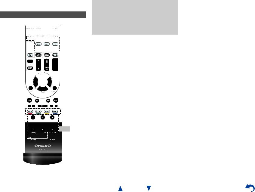
Remote Controller
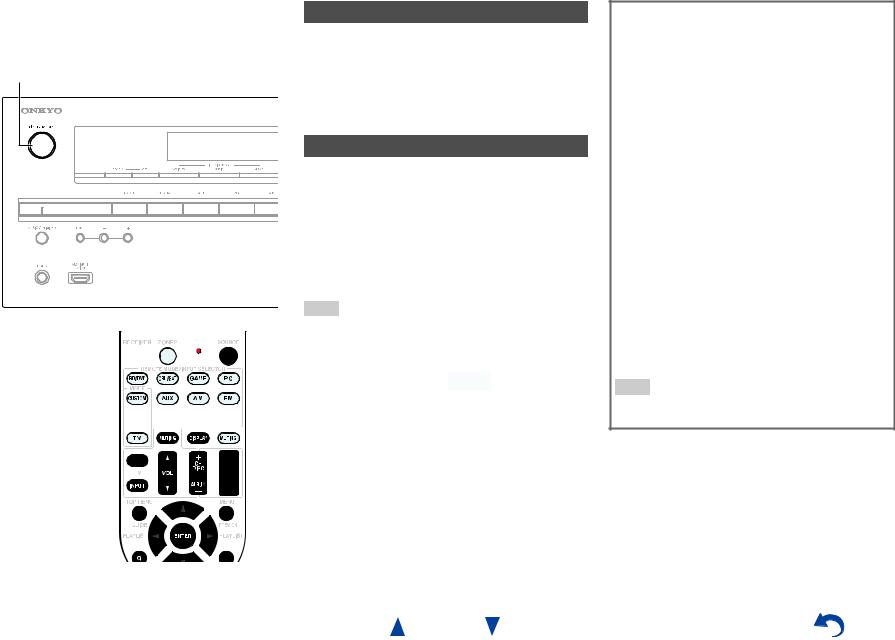
Controlling the AV Receiver
a


 b
b


*1


 g
g  hc
hc


 i
i


 d ac
d ac


d


 j
j  k
k
e


 e
e
bf


 l
l
Safety Information and Introduction
To control the AV receiver, press RECEIVER to select Receiver mode.
You can also use the remote controller to control Onkyo Blu-ray Disc/DVD player, CD player, and other components.
See “Entering Remote Control Codes” for more details ( page 69).
For detailed information, see the pages in parentheses.
a 8RECEIVER button (19)
b REMOTE MODE/INPUT SELECTOR buttons (22) c q/w/e/rand ENTER buttons
d Q SETUP button (43)
e Listening Mode buttons (35) f DIMMER button (41)
g MUTING button (42) h DISPLAY button (41) i VOL q/wbutton (22) j RETURN button
k HOME button (40)
lSLEEP button (41)
Controlling the tuner
To control the AV receiver’s tuner, press AM or FM (or
RECEIVER).
a q/wbuttons (30)
b D.TUN button (30)
c DISPLAY button
d CH +/– button (31)
e Number buttons (30)
*1 To control a component, you must first enter the remote control code.
See “Entering Remote Control Codes” for more details ( page 69).
En-10
Connecting the AV
Receiver
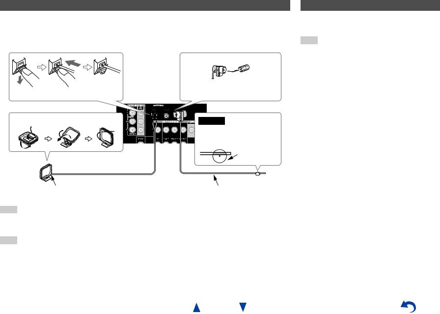
Connecting Your Speakers
Speaker Configuration
The following table indicates the channels you should use depending on the number of speakers that you have.
No matter how many speakers you use, a powered subwoofer is recommended for a really powerful and solid bass.
To get the best from your surround sound system, you need to set the speaker settings automatically ( page 32) or manually ( page 50).
|
|
|
|
|
|
|
|
|
|
|
|
|
|
Number of speakers |
2 3 4 5 6 |
7 |
7 |
||||||||||
|
|
|
|
|
|
||||||||
Front speakers |
|
|
|
|
|||||||||
|
|
|
|
|
|
|
|
||||||
Center speaker |
|
|
|
|
|
|
|||||||
|
|
|
|
|
|
|
|
||||||
Surround speakers |
|
|
|
|
|
|
|||||||
|
|
|
|
|
|
|
|
|
|
|
|
|
|
Surround back speaker*1*2 |
|
|
|
|
|
|
|
|
|
|
|
|
|
|
|
|
|
|
|
|
|||||||
Surround back speakers*2 |
|
|
|
|
|
|
|
|
|
|
|
|
|
Front high speakers*2 |
|
|
|
|
|
|
|
|
|
|
|
|
|
*1 If you’re using only one surround back speaker, connect it to the SURROUND BACK or FRONT HIGH L terminals.
*2 Front high and surround back speakers cannot be used at the same time.
Connecting the Speaker Cables
The following illustration shows how to connect the speakers to each pair of terminals. If you’re using only one surround back speaker, connect it to the SURROUND BACK or FRONT HIGH L terminals.
Tip
•You can specify whether surround back or front high speakers are connected in the “Speaker Configuration” menu ( page 50) or during Audyssey 2EQ® Room Correction and Speaker Setup ( page 32).
Connections
|
|
|
|
|
|
|
Surround |
Surround |
|
|
|
|
|
|
|
|
|
|
|
|
|
|
||||||||||||||||||||
|
|
|
|
|
|
|
|
right |
|
|
|
|
left |
|
|
|
|
|
|
|
|
|
|
|
|
|
|
|||||||||||||||
|
|
|
|
|
|
|
|
|
|
|
|
|
|
|
|
|
|
|
|
|
|
|
|
|
|
|
|
|
|
|
|
|
|
|
|
|
|
|
|
|
|
|
|
|
|
|
|
|
|
|
|
|
|
|
|
|
|
|
|
|
|
|
|
|
|
|
|
|
|
|
|
|
|
|
|
|
|
|
|
|
|
|
|
|
|
|
|
|
|
|
|
|
|
|
|
|
|
|
|
|
|
|
|
|
|
|
|
|
|
|
|
|
|
|
|
|
|
|
|
|
|
|
|
|
|
|
|
|
|
|
|
|
|
|
|
|
|
|
|
|
|
|
|
|
|
|
|
|
|
|
|
|
|
|
|
|
|
|
|
|
|
|
|
|
|
|
|
|
|
|
|
|
|
|
|
|
|
|
|
|
|
|
|
|
|
|
|
|
|
|
|
|
|
|
|
|
|
|
|
|
|
|
|
|
|
|
|
|
|
|
|
|
|
|
|
|
|
|
|
|
|
|
|
|
|
|
|
|
|
|
|
|
|
|
|
|
|
|
|
|
|
|
|
|
|
|
|
|
|
|
|
|
|
|
|
|
|
|
|
|
|
|
|
|
|
|
|
|
|
|
|
|
|
|
|
|
|
|
|
|
|
|
|
|
|
|
|
|
|
|
|
|
|
|
|
|
|
|
|
|
|
|
|
|
|
|
|
|
|
|
|
|
|
|
|
|
|
|
|
|
|
|
|
|
|
|
|
|
|
|
|
|
|
|
|
|
|
|
|
|
|
|
|
|
|
|
|
|
|
|
|
|
|
|
|
|
|
|
|
|
|
|
|
|
|
|
|
|
|
|
|
|
|
|
|
|
|
|
|
|
|
|
|
|
|
|
|
|
|
|
|
|
|
|
|
|
|
|
|
|
|
|
|
|
|
|
|
|
|
|
|
|
|
|
|
|
|
|
|
|
|
|
|
|
|
|
|
|
|
|
|
|
|
|
|
|
|
|
|
|
|
|
|
|
|
|
|
|
|
|
|
|
|
|
|
|
|
|
|
|
|
|
|
|
|
|
|
|
|
|
|
|
|
|
|
|
|
|
|
|
|
|
|
|
|
|
|
|
|
|
|
|
|
|
|
|
|
|
|
|
|
|
|
|
|
|
|
|
|
|
|
|
|
|
|
|
|
|
|
|
|
|
|
|
|
|
|
|
|
|
|
|
|
|
|
|
|
|
|
|
|
|
|
|
|
|
|
|
|
|
|
|
|
|
|
|
|
|
|
|
|
|
|
|
|
|
|
|
|
|
|
|
|
|
|
|
|
|
|
|
|
|
|
|
|
|
|
|
|
|
|
|
|
|
|
|
|
|
|
|
|
|
|
|
|
|
|
|
|
|
|
|
|
|
|
|
|
|
|
|
|
|
|
|
|
|
|
|
|
|
|
|
|
|
|
|
|
|
|
|
|
|
|
|
|
|
|
|
|
|
|
|
|
|
|
|
|
|
|
|
|
|
|
|
|
|
|
|
|
|
|
|
|
|
|
|
|
|
|
|
|
|
|
|
|
|
|
Surround back/ |
Surround back/ |
Front right |
Front left |
Center |
Front high |
Front high |
|
|
|
right |
left |
|
|
|
■Screw-type speaker terminals
Strip 1/2" to 5/8" (12 to 15 mm) of insulation from the ends of the speaker cables, and twist the bare wires tightly, as shown.
1/2" to 5/8" (12 to 15 mm)
■Push-type speaker terminals
Strip 3/8" to 1/2" (10 to 12 mm) of insulation from the ends of the speaker cables, and twist the bare wires tightly, as shown.
3/8" to 1/2"(10 to 12 mm)
■Banana Plugs
•If you are using banana plugs, tighten the speaker terminal before inserting the banana plug.
•Do not insert the speaker code directly into the center hole of the speaker terminal.
En-11

Attaching the Speaker Cable Labels
The speaker terminals are color-coded for identification purpose.
Speaker |
Color |
Front left, Front high left, Zone 2 left |
White |
|
|
Front right, Front high right, Zone 2 right |
Red |
|
|
Center |
Green |
|
|
Surround left |
Blue |
|
|
Surround right |
Gray |
|
|
Surround back left |
Brown |
|
|
Surround back right |
Tan |
|
|
The supplied speaker cable labels are also color-coded and you should attach them to the positive (+) side of each speaker cable in accordance with the table above. Then all you need to do is to match the color of each label to the corresponding speaker terminal.
•Be careful not to short the positive and negative wires. Doing so may damage the AV receiver.
•Make sure the metal core of the wire does not have contact with the AV receiver’s rear panel. Doing so may damage the AV receiver.
Speaker Connection Precautions
Read the following before connecting your speakers:
• You can connect speakers with an impedance of between 6 and 16 ohms. If you use speakers with a lower impedance, and use the amplifier at high volume levels for a long period of time, the built-in amp protection circuit may be activated.
•Disconnect the power cord from the wall outlet before making any connections.
•Read the instructions supplied with your speakers.
•Pay close attention to speaker wiring polarity. In other words, connect positive (+) terminals only to positive (+) terminals, and negative (–) terminals only to negative (–) terminals. If you get them the wrong way around, the sound will be out of phase and will sound unnatural.
•Unnecessarily long, or very thin speaker cables may affect the sound quality and should be avoided.
En-12
Connections
•Don’t connect more than one cable to each speaker terminal. Doing so may damage the AV receiver.
•Don’t connect one speaker to several terminals.
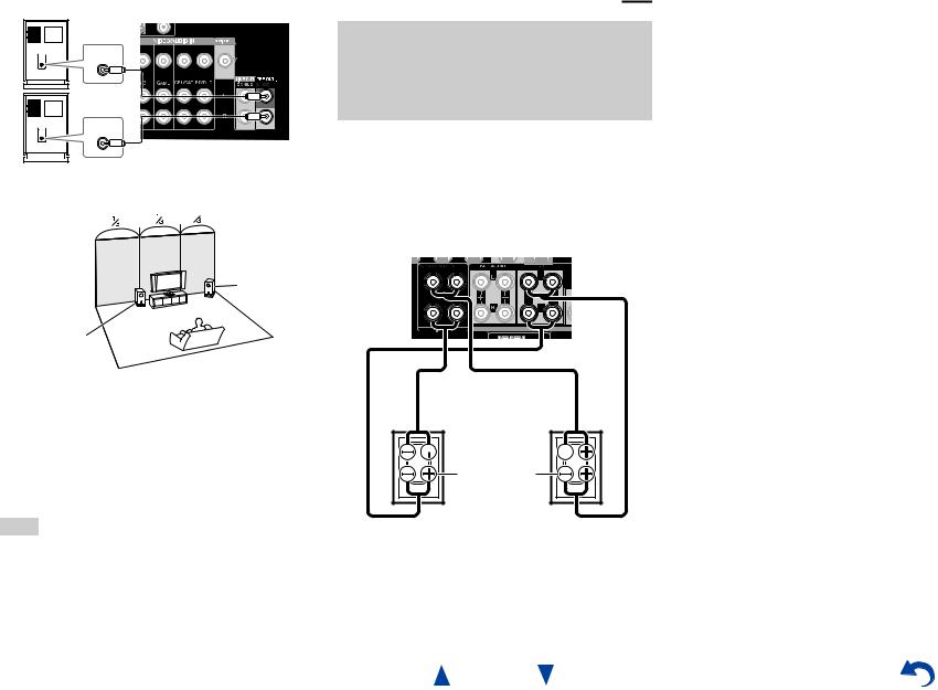
Using Powered Subwoofers
LINE INPUT
LINE INPUT
Powered subwoofer
Corner position
1/3 of wall position
To find the best position for your subwoofer, while playing a movie or some music with good bass, experiment by placing your subwoofer at various positions within the room, and choose the one that provides the most satisfying results.
You can connect the powered subwoofer with two SUBWOOFER PRE OUT jacks respectively. The same signal is output from each jack.
Tip
•If your subwoofer is unpowered and you’re using an external amplifier, connect the subwoofer pre out jack to an input on the amplifier.
Connections
Bi-amping the Front Speakers
Important:
•When making the bi-amping connections, be sure to remove the jumper bars that link the speakers’ tweeter (high) and woofer (low) terminals.
•Bi-amping can be used only with speakers that support biamping. Refer to your speaker manual.
Bi-amping provides improved bass and treble performance. When bi-amping is used, the AV receiver is able to drive up to a 5.1 speaker system in the main room.
Once you’ve completed the bi-amping connections as shown and turned on the AV receiver, you must set the speaker setting to enable bi-amping ( page 50).

 Tweeter (high)

Woofer (low) |
Front right |
Front left |
En-13
About AV Connections
Connecting AV components |
|||||
HDMI cable |
|
|
|
: Video & Audio |
|
TV, projector, etc. |
|
|
|
||
|
|
|
|
|
|
|
|
|
AV receiver |
|
|
|
|
|
|
|
|
|
|
|
|
|
|
Blu-ray Disc/ |
|
DVD player |
Game console |
Other cables
|
|
|
|
|
: Video |
|
|
: Audio |
|||
|
|
|
|
|
|
|
|||||
TV, projector, etc. |
|
||||||||||
|
|
|
|
|
|
AV receiver |
|
||||
|
|
|
|
|
|||||||
|
|
|
|
|
|
|
|
|
|
|
|
|
|
|
|
|
|
|
|
|
|
|
|
|
|
|
|
|
|
|
|
|
|
|
|
|
|
|
|
|
|
|
|
|
|
|
|
Blu-ray Disc/ |
|
DVD player |
Game console |
•Before making any AV connections, read the manuals supplied with your AV components.
•Don’t connect the power cord until you’ve completed and double-checked all AV connections.
• Push plugs in all the way to make |
|
|
|
|
|
Right! |
|
||||||||||
good connections (loose connections |
|
|
|
|
|
|
|
|
|
|
|
|
|
|
|
|
|
can cause noise or malfunctions). |
|
|
|
|
|
|
|
|
|
|
|
|
|
|
|
|
|
• To prevent interference, keep audio |
|
|
|
|
|
|
|
|
|
|
|
|
|
|
|
|
|
and video cables away from power |
|
|
|
|
|
Wrong! |
|
||||||||||
|
|
|
|
|
|
||||||||||||
|
|
|
|
|
|
||||||||||||
cords and speaker cables. |
|
|
|
|
|
|
|
|
|
|
|
|
|
|
|
|
|
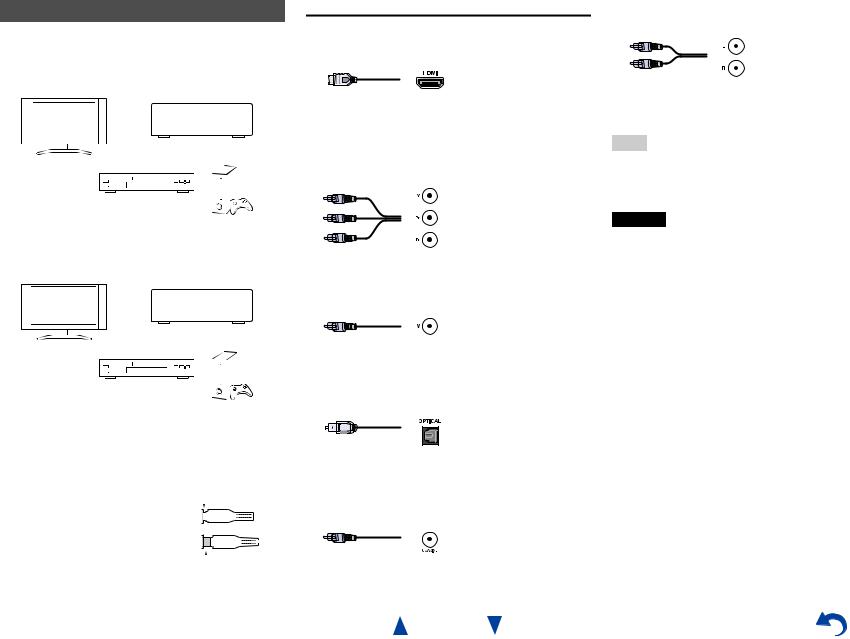
AV Cables and Jacks
■HDMI
HDMI connections can carry digital video and audio.
■Component video
Component video separates the luminance (Y) and color difference signals (PB, PR), providing the best picture quality (some TV manufacturers label their component video sockets slightly differently).
Y |
Green |
PB |
Blue |
PR |
Red |
■Composite video
Composite video is commonly used on TVs, DVDs, and other video equipment.
Yellow
■Optical digital audio
Optical digital connections allow you to enjoy digital sound such as PCM*1, Dolby Digital or DTS. The audio quality is the same as coaxial.
■Coaxial digital audio
Coaxial digital connections allow you to enjoy digital sound such as PCM*1, Dolby Digital or DTS. The audio quality is the same as optical.
Orange
En-14
Connections
■Analog audio (RCA)
Analog audio connections (RCA) carry analog audio.
White
Red
*1 For PCM signals, the supported sampling rates are 32/44.1/48/88.2/96 kHz. With HDMI connections, 176.4 and 192 kHz are also supported.
Note
•The AV receiver does not support SCART plugs.
•The AV receiver’s optical digital jacks have shutter-type covers that open when an optical plug is inserted and close when it’s removed. Push plugs in all the way.
Caution
•To prevent shutter damage, hold the optical plug straight when inserting and removing.
Connecting Components with HDMI
Satellite/cable set-top box, etc.
Personal computer
Game console
*If your TV doesn’t support Audio Return Channel (ARC), you need to connect an optical digital cable together with the HDMI cable to the AV receiver.
*When listening to an HDMI component through the AV receiver, set the HDMI component so that its video can be seen on the TV screen (on the TV, select the input of the HDMI component connected to the AV receiver). If the TV power is off or the TV is set to another input source, this may result in no sound from the AV receiver or the sound may be cut off.
TV, projector, etc.
Blu-ray Disc/DVD player
Connect your components to the appropriate jacks. The default input assignments are shown below.
: Assignment can be changed ( page 48).
Jack |
Components |
|
IN1 |
Blu-ray Disc/DVD player |
|
|
|
|
IN2 |
Satellite/cable set-top box, etc. |
|
|
|
|
IN3 |
Game console |
|
|
|
|
IN4 |
Personal computer |
|
|
|
|
IN5 |
Other components |
|
|
|
|
IN6 |
Other components |
|
|
|
|
IN7 |
Other components |
|
|
|
|
Front |
Camcorder, etc. |
|
|
|
|
OUT MAIN |
TV |
|
|
|
|
OUT SUB |
Projector, etc. |
|
|
|
|
See also:
•“Connection Tips and Video Signal Path” ( page 83)
•“Using an RIHD-compatible TV, Player, or Recorder” ( page 86)
•“About HDMI” ( page 88)
Tip
•To listen to the audio of a component connected via HDMI through your TV’s speakers, enable “HDMI Through” ( page 60) and set the AV receiver to standby mode.
En-15
Connections
Camcorder, etc.
Note
•In the case of Blu-ray Disc/DVD players, if no sound is output despite following the above-mentioned procedure, set your Bluray Disc/DVD player’s HDMI audio settings to PCM.
Audio Return Channel (ARC) function
The Audio Return Channel (ARC) function enables an HDMI capable TV to send the audio stream to HDMI OUT MAIN on the AV receiver.
•This function can be used when:
–Your TV is ARC capable, and
–The TV/CD input selector is selected, and
–“HDMI Control(RIHD)” is set to “On”( page 60), and
–“Audio Return Channel” is set to “Auto” ( page 61).
MHL (Mobile High-Definition Link)
With its support for MHL (Mobile High-Definition Link), the AUX (Front) input allows you to deliver highdefinition video from a connected mobile device.
Connecting Your Components
A B |
C D B E F
The on-screen menus appear only on a TV that is connected to HDMI OUT MAIN. If your TV is connected to other video outputs, use the AV receiver’s display when changing settings.
: Assignment can be changed ( page 49).
No. |
Jack/Port |
Components |
|
A |
USB, VIDEO*1 |
iPod/iPhone (video |
|
|
|
playback) |
|
|
|
|
|
B |
USB*2*3 |
iPod/iPhone, MP3 player, |
|
|
|
USB flash drive |
|
|
|
|
|
C |
DIGITAL IN |
|
|
|
|
|
|
|
OPTICAL 1 (GAME) |
Game consoles |
|
|
|
|
|
|
OPTICAL 2 (TV/CD) |
TV, CD player |
|
|
|
|
|
|
COAXIAL 1 (BD/DVD) |
Blu-ray Disc/DVD player |
|
|
|
|
|
|
COAXIAL 2 (CBL/SAT) |
Satellite/cable set-top box, |
|
|
|
RI dock, etc. |
|
|
|
|
|
D |
COMPONENT VIDEO |
|
|
|
|
|
|
|
IN (CBL/SAT) |
Satellite/cable set-top box, |
|
|
|
RI dock, etc. |
|
|
|
|
|
|
OUT |
TV, projector, etc. |
|
|
|
|
|
E |
ETHERNET |
Router |
|
|
|
|
|
F |
MONITOR OUT |
TV, projector, etc. |
|
|
|
|
|
|
BD/DVD IN |
Blu-ray Disc/DVD player |
|
|
|
|
|
|
CBL/SAT IN |
Satellite/cable set-top box, |
|
|
|
etc. |
|
|
|
|
|
|
GAME IN |
Game console, RI dock |
|
|
|
|
|
|
PC IN |
Personal computer |
|
|
|
|
|
|
TV/CD IN |
TV, CD player, cassette |
|
|
|
tape deck, MD, CD-R, |
|
|
|
Turntable*4, RI dock |
|
Connections
Note
*1 When the USB input is selected, you can input video signals from the VIDEO jack. Video signals input from VIDEO will be output from the MONITOR OUT and HDMI output jacks.
*2 Do not connect the AV receiver’s USB port to a USB port on your computer. Music on your computer cannot be played through the AV receiver in this way.
*3 Only the front-panel USB input is compatible with iPod/iPhone.
*4 Connect a turntable (MM) that has a phono preamp built-in. If your turntable (MM) doesn’t have it, you’ll need a commercially available phono preamp.
If your turntable has a moving coil (MC) type cartridge, you’ll need a commercially available MC head amp or MC transformer as well as a phono preamp. See your turntable’s manual for details.
•With connection C, you can enjoy Dolby Digital and DTS. (To listen in Zone 2 as well, use C and F.)
•With connection F, you can enjoy audio from external components while you are in Zone 2.
•With connection F, if your Blu-ray Disc/DVD player has both the main stereo and multichannel outputs, be sure to connect the main stereo.
Connect your components to the appropriate jacks. The default input assignments are shown below. See “Connection Tips and Video Signal Path” for more information ( page 83).
En-16
Connections
Connecting Onkyo RI Components
1 |
Make sure that each Onkyo component is connected |
|
with an analog audio cable (connection F in the |
|
hookup examples) ( page 16). |
2 |
Make the uconnection (see the illustration). |
3 |
If you’re using an RI Dock, or cassette tape deck, |
|
change the Input Display ( page 41). |
With u(Remote Interactive), you can use the following special functions:
System On/Auto Power On
When you start playback on a component connected via u, while the AV receiver is on standby, the AV receiver will automatically turn on and select that component as the input source.
Direct Change
When playback is started on a component connected via u, the AV receiver automatically selects that component as the input source.
Remote Control
You can use the AV receiver’s remote controller to control your other u-capable Onkyo components, pointing the remote controller at the AV receiver’s remote control sensor instead of the component. You must enter the appropriate remote control code first ( page 70).
R L
ANALOG
AUDIO OUT
e.g., cassette tape deck
R L
ANALOG
AUDIO OUT
RI Dock
Note
•Use only ucables for uconnections. ucables are supplied with Onkyo components.
•Some components have two ujacks. You can connect either one to the AV receiver. The other jack is for connecting additional u-capable components.
•Connect only Onkyo components to ujacks. Connecting other manufacturer’s components may cause a malfunction.
•Some components may not support all ufunctions. Refer to the manuals supplied with your Onkyo components.
•While Zone 2 is on, the System On/Auto Power On and Direct Change ufunctions do not work.
En-17
Connecting the Antennas
This section explains how to connect the supplied indoor FM antenna and AM loop antenna.
The AV receiver won’t pick up any radio signals without any antenna connected, so you must connect the antenna to use the tuner.
Push. |
Insert wire. |
Release. |
Insert the plug fully into the jack. |
|
Assembling the AM loop antenna |
Caution |
|
|
|
• Be careful not to injure yourself |
|
when using thumbtacks. |
|
Thumbtacks, etc. |
AM loop antenna (supplied) |
Indoor FM antenna (supplied) |
Note
•Once your AV receiver is ready for use, you’ll need to tune into a radio station and position the antenna to achieve the best possible reception.
•Keep the AM loop antenna as far away as possible from your AV receiver, TV, speaker cables, and power cords.
Tip
•If you cannot achieve good reception with the supplied indoor FM antenna, try a commercially available outdoor FM antenna instead.
•If you cannot achieve good reception with the supplied indoor AM loop antenna, try using it with a commercially available outdoor AM antenna.
Connections
Connecting the Power Cord
1 Plug the power cord into an AC wall outlet.
Note
•Before connecting the power cord, connect all of your speakers and AV components.
•Turning on the AV receiver may cause a momentary power surge that might interfere with other electrical equipment on the same circuit. If this is a problem, plug the AV receiver into a different branch circuit.
En-18
Turning On/Off the AV
Receiver
8ON/STANDBY
8RECEIVER 

RECEIVER 


Turning On
1 Press 8ON/STANDBY on the front panel. or
Press RECEIVER followed by 8RECEIVER on the remote controller.
The AV receiver comes on and its display lights.
Turning Off
1 Press 8ON/STANDBY on the front panel. or
Press RECEIVER followed by 8RECEIVER on the remote controller.
The AV receiver will enter standby mode. To prevent any loud surprises when you turn on the AV receiver, always turn down the volume before you turn it off.
Tip
•The HYBRID STANDBY indicator may light depending on the status of settings ( page 47).
•For details on power management settings, see “Auto Standby” ( page 61).
Turning On & Basic Operations
Smooth Operation in a Few Easy Steps (Initial Setup)
To ensure smooth operation, here’s a few easy steps to help you configure the AV receiver before you use it for the very first time. These settings only need to be made once. See “Initial Setup” for details ( page 20).
If the “Firmware Update Available” window appears.
When a new version of the firmware is available, the notification window “Firmware Update Available” pops up. This notification only appears when the AV receiver is connected to your home network
( page 89). To perform the firmware update, follow the instructions on screen.
Use q/wand ENTER on the AV receiver or remote controller to select one of the options.
`Update Now:
Starts the firmware update.
Refer to “Firmware Update” ( page 79).
`Remind me Later:
The update notification will pop up again the next time you turn the AV receiver on.
`Never Remind me:
Disables the automatic update notification.
Tip
•The update notification window can be enabled or disabled in “Update Notice” ( page 62).
En-19
Initial Setup
This section explains the settings that we recommend you to make before using the AV receiver for the very first time. A setup wizard is launched upon first-time use to let you perform those settings.
The on-screen menus appear only on a TV that is connected to HDMI OUT MAIN.
Selecting the Language for the Onscreen Setup Menus
This step determines the language used for the onscreen setup menus. See “Language” in “OSD Setup”
( page 59).
Tip
•Pressing HOME will close the setup wizard. To restart the initial setup, select “Initial Setup” in the “Hardware Setup” menu ( page 62).
After selecting the language for on-screen setup menus, a welcome screen is displayed.
Initial Setup
Welcome to initial setup. Have you connected all the speakers and devices?
Before starting, please connect speakers and sources.
Now, would you like to start initial setup?
1st Step : Audyssey 2EQ: Auto Setup 2nd Step : Source Connection
3rd Step : Remote Mode Setup 4th Step : Network Connection
Yes
No
HOME Exit
1 Use q/won the AV receiver or remote controller to select one of the following options, and then press
ENTER.
`Yes:
Continues to “Audyssey 2EQ: Auto Setup”. `No:
Skips the settings and terminates the initial setup. The setup wizard goes to “Terminating the Initial Setup”. You can always restart the initial setup by selecting “Initial Setup” in the “Hardware Setup” menu ( page 62).
Turning On & Basic Operations
Audyssey 2EQ: Auto Setup
This step performs the automatic speaker setup.
1 Use q/wto select one of the following options, and then press ENTER.
`Do it Now:
The automatic speaker setup is performed following instructions on screen. Refer to step 2 of “Using the Automatic Speaker Setup”
( page 32). When this setting is complete, the setup wizard continues to “Source Connection”.
`Do it Later: Skips this setting.
Press ENTER and continue to “Source Connection”.
En-20
Source Connection
This step checks the connection of source components.
1 Use q/wto select one of the following options, and then press ENTER.
`Yes, Continue: Performs the checkings.
`No, Skip:
Skips this step and continues to “Remote Mode Setup”.
2 Select the input selector for which you want to check the connection and press ENTER.
The picture of the corresponding source should appear on screen with a verification prompt.
3 When prompted, use q/wto select one of the following options and then press ENTER.
`Yes:
Confirms that the source is properly displayed.
`No:
Displays an error report. Follow the troubleshooting instructions and recheck the source.
4 Use q/wto select one of the following options, and then press ENTER.
`Yes:
Returns to step 2.
`No, Done Checking:
The setup wizard continues to “Remote Mode Setup”.
Remote Mode Setup
With this step, you can enter remote control codes for the components you want to operate.
1 Use q/wto select one of the following options, and then press ENTER.
`Yes:
Performs the remote control code input. Refer to step 5 of “Looking up for Remote Control Codes” ( page 68).
`No, Skip:
Skips this step and continues to “Network Connection”.
2 When you’re finished, select one of the following options and press ENTER.
`Yes, Done:
The setup wizard continues to “Network Connection”.
`No, not yet:
You can enter other remote control codes.
Turning On & Basic Operations
Network Connection
This step checks your network connection.
1 Use q/wto select one of the following options, and then press ENTER.
`Yes:
Performs the checkings.
`No, Skip:
Skips this step and terminates the initial setup.
Note
•If you use both wired and wireless network connections, the wireless will take priority.
For further details, see the instruction manual provided with your wireless device.
2 Follow the instructions on screen to perform the network checking.
The checking is complete when the message “Successfully connected.” appears at the middle of the screen. Press ENTER to terminate the initial setup.
3 If an error message appears, select one of the following options and press ENTER.
`Retry:
Performs the checking again.
`No, Do it Later:
Skips this step and terminates the initial setup. The setup wizard goes to “Terminating the Initial Setup”.
Terminating the Initial Setup
This step ends the initial setup process.
1 Press ENTER.
To restart the initial setup, select “Initial Setup” in the “Hardware Setup” menu ( page 62).
En-21
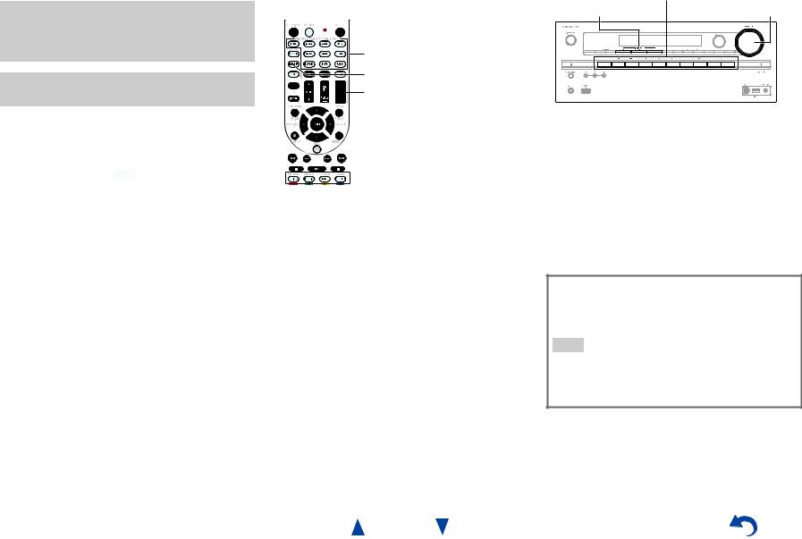
Playback
The on-screen menus appear only on a TV that is connected to HDMI OUT MAIN. If your TV is connected to other video outputs, use the AV receiver’s display when changing settings.
This section describes the procedure for using the remote controller, unless otherwise specified.
Turning On & Basic Operations
|
Operating on the AV receiver |
|
Playing the Connected Component |
||
|
||
|
|
Operating with the remote controller |
Input selector buttons |
||
LISTENING MODE |
MASTER VOLUME |
||
|
|||
INPUT SELECTOR |
|
|
|
RECEIVER |
|
|
|
VOL q/w |
|
|
|
1 |
|
|
Listening mode buttons |
|
|
||
Press RECEIVER followed by an INPUT |
|||
|
SELECTOR button. |
||
2 |
Start playback on the source component. |
||
|
See also: |
||
|
• “Playing an iPod/iPhone via USB” ( page 24) |
||
|
• “Playing a USB Device” ( page 25) |
||
|
• “Listening to vTuner Internet Radio” ( page 26) |
||
|
• “Registering Other Internet Radio” ( page 27) |
||
|
• “Playing Music Files on a Server” ( page 28) |
||
|
• “Remote Playback” ( page 29) |
||
|
• “Listening to AM/FM Radio” ( page 30) |
||
|
• “iPod/iPhone Playback via Onkyo Dock” |
||
|
( page 66) |
||
|
• “Controlling Other Components” ( page 68) |
||
3 |
To adjust the volume, use VOL q/w. |
||
4 |
Select a listening mode and enjoy! |
||
|
See also: |
||
• “Using the Listening Modes” ( page 35)
1 |
Use the input selector buttons to select the input |
|
source. |
2 |
Start playback on the source component. |
3 |
To adjust the volume, use the MASTER VOLUME |
|
control. |
4 |
Select a listening mode and enjoy! |
Screen Saver
If there is no video signal on the current input source and no operation for a specific time (three minutes by default), a screen saver automatically comes on.
Tip
•The time until the screen saver activates itself can be changed in the “Screen Saver” setting ( page 59).
•The screen will return to its previous state if the AV receiver is operated.
En-22
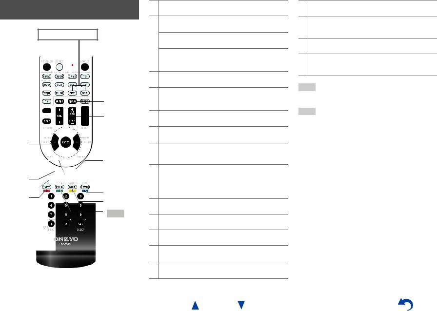
Controlling Contents of USB or Network Devices
Press USB or NET first.
h
i
a


 j
j
b


 k c
k c  l d
l d


 m
m
e

 n
n
f |
o |
|
g |
||
p |
||
|
||
|
q |
aTOP MENU
This button displays the top menu for each media or service.
bq/wand ENTER
These buttons navigate through the menus. e/r
This button cycles through pages.
PLAYLIST e/r
In Standard Mode (iPod/iPhone), this button selects playlists.
c1
This button starts playback.
d7
This button selects the beginning of the current song. Pressing this button twice selects the previous song.
e5
This button fast-reverses the current song.
f3
This button pauses playback.
gSEARCH
You can toggle between the playback screen and the list screen during playback.
hDISPLAY
This button switches between song information during playback.
Press this button while the list screen is displayed to return to the playback screen.
iALBUM +/–
In Standard Mode (iPod/iPhone), this button selects albums.
jMENU
This button displays the menu of Internet radio services.
kRETURN
This button returns to the previous menu.
l4
This button fast-forwards the current song.
m6
This button selects the next song.
Turning On & Basic Operations
n2
This button stops playback.
oMODE
You can switch between Standard Mode and Extended Mode during iPod/iPhone playback.
pRANDOM
This button performs random playback.
qREPEAT
Press this button repeatedly to cycle through the repeat modes.
Tip
•See “Controlling Other Components” about the operation of other components ( page 68).
Note
•The buttons you can use will differ depending on the devices and media used for playback.
En-23
Understanding Icons on the Display
This section describes icons that appear on the AV receiver’s display during media playback.
Icon Description
Folder
Track
Playback
Pause
Fast Forward
Fast Reverse
Artist
Album
Repeat One Track
Repeat Folder (USB Device)
Repeat
Shuffle
Shuffle Album (iPod/iPhone)
Playing an iPod/iPhone via USB
The on-screen menus appear only on a TV that is connected to HDMI OUT MAIN.
This section explains how to play music/video files on the iPod/iPhone.
Compatible iPod/iPhone models Made for:
iPod touch (1st, 2nd, 3rd and 4th generation), iPod classic, iPod nano (2nd, 3rd, 4th, 5th and 6th generation),
iPhone 4S, iPhone 4, iPhone 3GS, iPhone 3G, iPhone
1 Press USB repeatedly to select the “USB(Front)” input.
Tip
•The same operation can be done by selecting “USB” in the Home menu.
2 Connect the USB cable that comes with the iPod/iPhone to the USB port on the front of the AV receiver.
While reading the contents of your iPod/iPhone, the message “Connecting...” appears on the AV receiver’s display.
The USB indicator lights. It will flash if the AV receiver cannot read the iPod/iPhone.
Tip
•When connecting your iPod/iPhone with a USB cable, we recommend you use an official USB cable from Apple Inc.
En-24
Turning On & Basic Operations
3 Press MODE repeatedly to switch to Extended Mode (Music) or Extended Mode (Video).
A list of your iPod/iPhone model’s contents appears.
Tip
•If you want to operate using the iPod/iPhone or the remote controller, press MODE repeatedly to switch to Standard mode.
•When you disconnect the iPod/iPhone, the AV receiver remembers the current mode. This means that if you disconnect when in Extended Mode (Music), the AV receiver will start in Extended Mode (Music) the next time you connect the iPod/iPhone.
4 Use q/wto select a folder, and then press ENTER to open it.
Tip
•You can also use the q/w, ENTER and TUNING MODE buttons on the front panel. TUNING MODE allows you to switch modes.
5 Use q/wto select a music/video file, and press ENTER or 1to start playback.
Note
•While the message “Connecting...” appears on the AV receiver’s display, do not disconnect the USB cable supplied with your iPod/iPhone or the USB device from the USB port.
•If you connect an iPod or iPhone to the USB port, no sound will be output from the headphones jack.
Extended Mode (Music) Control
The music content information is displayed (lists are displayed), and you can control the music content while looking at the screen.
Top screen list:
Playlists, Artists, Albums, Genres, Songs, Composers, Shuffle Songs, Now Playing.
Note
•In this mode, video contents are not displayed, even if they are input from the VIDEO jack on the AV receiver’s front panel.
Extended Mode (Video) control
The video content information is displayed (lists are displayed), and you can control the video content while looking at the screen.
Top screen list:
Movies, Music Videos, TV Shows, Video Podcasts, Rentals.
Note
•To view the video contents of your iPod/iPhone, connect it to the USB port and VIDEO jack on the AV receiver’s front panel, using the official Apple Composite AV Cable.
•Depending on your iPod/iPhone model and generation, the displayed items may vary and the support for Extended Mode (Video) is not guaranteed.
Standard Mode Control
The content information is not displayed, but can be operated using the iPod/iPhone or the remote controller.
Turning On & Basic Operations
Playing a USB Device
The on-screen menus appear only on a TV that is connected to HDMI OUT MAIN.
This section explains how to play music files from a USB device (e.g., USB flash drives and MP3 players).
See also:
• “Network/USB Features” ( page 89).
1 |
Press USB repeatedly to select the “USB(Front)” or |
|
“USB(Rear)” input. |
2 |
Plug your USB device into the AV receiver’s USB |
|
port. |
|
The USB indicator lights. It will flash if the AV |
|
receiver cannot read the USB device. |
3 |
Press ENTER. |
|
A list of the device’s contents appears. To open a |
|
folder, use q/wto select it, and then press ENTER. |
4 |
Use q/wto select a music file, and press ENTER or |
|
1to start playback. |
Note
•While the message “Connecting...” appears on the AV receiver’s display, do not disconnect the USB cable supplied with your iPod/iPhone or the USB device from the USB port.
En-25
Listening to vTuner Internet Radio
You need to connect the AV receiver to your home network ( page 89). The on-screen menus appear only on a TV that is connected to HDMI OUT MAIN.
The vTuner Internet Radio Service is a portal site featuring radio stations from all over the world.
You can search for stations by categories such as genre or location. The AV receiver is preinstalled with this service.
1 |
Press NET. |
|
|
The network service screen appears, and the NET |
|
|
indicator lights. If it flashes, verify that the Ethernet |
|
|
cable is firmly connected to the AV receiver. |
|
|
|
|
|
Tip |
|
|
• The same operation can be done by selecting “Network |
|
|
Service” in the Home menu. |
|
2 |
Use q/w/e/rto select “vTuner Internet Radio” |
|
|
and then press ENTER. |
|
3 |
Use q/wto select a program and then press |
|
|
ENTER. |
|
Playback starts.
My Music
0 : 11
Great Artist
My Favorite
Tip
•You can find stations similar to the one being played. During playback, press MENU on the remote controller, select “Stations like this” and press ENTER.
Turning On & Basic Operations
Adding vTuner Internet Radio Stations to Favorites
There are two ways you can register specific Internet radio stations (programs) from the vTuner Internet Radio.
Adding to My Favorites
The selected program will be added to “My Favorites” on the network service screen, which appears when pressing NET on the remote controller.
1.Press MENU with the station selected or while a station is playing.
2.Use q/wto select “Add to My Favorites”, and press
ENTER.
3.Use q/w/e/rto select “OK”, and press ENTER.
Tip
• You can rename the stations saved in “My Favorites”.
Adding to vTuner Internet Radio’s Favorites
Select “vTuner Internet Radio” and press ENTER to display the “Favorites” folder that appears on the same screen as “Stations By Genre”, “Stations By Location”, etc. This is where your favorite Internet radio bookmarks will be stored.
To register your favorite stations using a personal computer, you need to connect your PC to the same network as the AV receiver. Enter the ID# (MAC address) of your unit on the http://onkyo.vtuner.com/. You can then register your favorite radio programs. The ID# is shown at the bottom of the “vTuner Internet Radio” top menu, and the AV receiver’s MAC address is shown on “Network” of the Setup menu
( page 62).
En-26

Registering Other Internet Radio
You need to connect the AV receiver to your home network ( page 89). The on-screen menus appear only on a TV that is connected to HDMI OUT MAIN.
Internet radio URLs in the following formats are supported: PLS, M3U, and podcast (RSS). However, depending on the type of data or audio format used by the Internet radio station, you may not be able to listen to some stations.
To listen to other Internet radio stations, you must register your station in “My Favorites” of the network service screen, as described below.
Note
•Services available may vary depending on the region. See the separate instructions for more information.
1 |
Select “Network” on the Setup menu to verify your |
|
IP address ( page 62). |
|
Take a note of the IP address. |
2 |
On your computer, start your web browser. |
3 |
Enter the AV receiver’s IP address in the browser’s |
|
Internet address (URL) field. |
|
If you are using Internet Explorer®, you can also enter |
|
the URL by selecting “Open...” on the “File” menu. |
|
Information on the AV receiver is then shown on your |
|
Internet browser (Web Setup). |
4 |
Click on the “My Favorites” tab, and enter the |
|
Internet radio station’s name and URL. |
5 Click “Save” to save the Internet radio station.
The Internet radio station is then added to “My Favorites”. To play the registered station, press NET, and then select “My Favorites” on the network service screen. A list of registered Internet radio stations appears. Select the one that you saved and press ENTER.
Tip
•If you want to add a new station directly from “My Favorites”, select an empty slot in the list and press MENU. Then, select “Create New Station” and press ENTER.
Pressing ENTER again will display the keyboard screen. Use that keyboard to enter the station’s name and URL respectively, and then press ENTER.
•If you want to delete a station saved in “My Favorites”, press MENU with the station selected or while the station is playing. Then, use q/wto select “Delete from My Favorites” and press ENTER. You can also delete stations from the Web Setup.
•If you want to rename a station, select the desired station and press MENU. Then, use q/wto select “Rename this station” and press ENTER.
•You can save up to 40 Internet radio stations.
En-27
Turning On & Basic Operations
Changing the Icon Layout on the Network Service Screen
The layout of icons can be customized by switching their positions on the network service screen.
1 |
Press NET. |
|
|
The network service screen appears, and the NET |
|
|
indicator lights. If it flashes, verify that the Ethernet |
|
|
cable is firmly connected to the AV receiver. |
|
|
|
|
|
Tip |
|
|
• The same operation can be done by selecting “Network |
|
|
Service” in the Home menu. |
|
2 |
Press MODE/D (blue) on the remote controller. |
|
3 |
Use q/w/e/rto select an icon to move, and then |
|
|
press ENTER. |
|
4 |
Use q/w/e/rto select another icon as the |
|
|
destination, and then press ENTER. |
|
The icons switch positions and the message “Completed!” appears.
If you press RETURN, the “Custom Mode” process will be cancelled or it will go back one step.
Playing Music Files on a Server |
5 Use q/wto select an item, and then press ENTER or |
You need to connect the AV receiver to your home network ( page 89). The on-screen menus appear only on a TV that is connected to HDMI OUT MAIN.
This section explains how to play music files on a computer or media server through the AV receiver (Server Playback).
1 |
Start your computer or media server. |
2 |
Press NET. |
The network service screen appears. The NET indicator lights. If it flashes, confirm the network connection.
Tip
•The same operation can be done by selecting “Network Service” in the Home menu.
1to start playback.
My favorite song 1 0 : 11
Artist name My favorite album
Note
•Depending on the media server, 5/4/3may not work.
•If the message “No Item.” appears, this means that no information can be retrieved from the server. In this case, check your server, network, and AV receiver connections.
3 Use q/w/e/rto select “DLNA”, and press ENTER.
Tip
• To go back to the previous screen, press RETURN.
4 Use q/wto select a server, and then press ENTER.
The menu is displayed according to the server functions.
Note
•The search function does not work with media servers which do not support this function.
•Photos and movies stored on a media server cannot be accessed from the AV receiver.
•Depending on the sharing settings in the media server, the AV receiver may not able to access the content. See the instruction manual of the media server.
Turning On & Basic Operations
Windows Media Player 11 Setup
This section explains how to configure Windows Media Player 11 so that the AV receiver can play the music files stored on your computer.
1 |
Start Windows Media Player 11. |
2 |
On the “Library” menu, select “Media Sharing”. |
|
The “Media Sharing” dialog box appears. |
3 |
Select the “Share my media” check box, and then |
|
click “OK”. |
|
A list of the supported devices appears. |
4 |
Select the AV receiver in the list, and then click |
|
“Allow”. |
|
The corresponding icon will be checked. |
5 |
Click “OK” to close the dialog box. |
This completes the Windows Media Player 11 configuration.
You can now play the music files in your Windows Media Player 11 library through the AV receiver.
Tip
•Windows Media Player 11 can be downloaded for free from the Microsoft web site.
En-28

Remote Playback
You need to connect the AV receiver to your home network ( page 89). The on-screen menus appear only on a TV that is connected to HDMI OUT MAIN.
Remote Playback means you can play the music files stored on a media server or personal computer with the AV receiver by operating the controller device in the home network.
Windows Media Player 12 Setup
This section explains how to configure Windows Media Player 12 so that the AV receiver can play the music files stored on your personal computer.
1 |
Start Windows Media Player 12. |
|
2 |
On the “Stream” menu, select “Turn on media |
|
|
streaming”. |
|
|
A dialog box appears. |
|
|
|
|
|
Tip |
|
|
• If the media streaming is already activated, clicking on |
|
|
“More streaming options...” in the “Stream” menu will |
|
|
display a list of the playback devices connected to the |
|
|
network. You can skip step 3. |
|
3 |
Move your cursor and click on “Turn on media |
|
|
streaming”. |
|
|
A list of media server appears. Wording may vary |
|
|
slightly depending on the network location. |
|
4 |
On the “Media streaming options”, select the AV |
|
|
receiver and confirm that it is set to “Allow”. |
|
5 Click “OK” to close the dialog box.
This completes the Windows Media Player 12 configuration.
You can now play the music files in your Windows Media Player 12 library.
Tip
•On the “Stream” menu, confirm that “Allow remote control of my Player...” is checked.
Using Remote Playback
1 |
Turn on the AV receiver. |
2 |
Start Windows Media Player 12. |
|
To enable remote playback, you must first configure |
|
Windows Media Player 12. |
3 |
On Windows Media Player 12, right-click on a |
|
music file. |
The right-click menu appears.
Tip
•For selecting another media server, select the desired media server from the “Other Libraries” menu on Windows Media Player 12.
4 Select the AV receiver in “Remote playback”.
The “Play to” window appears and playback on the AV receiver starts. Operations during remote playback can be made from the “Play to” window of Windows 7 on your personal computer.
A playback screen will be displayed on the connected TV.
En-29
Turning On & Basic Operations
5 Adjusting the Volume.
You can adjust the volume by adjusting the volume bar in the “Remote playback” window. The default maximum volume level is 64. If you wish to change this, enter the value from the Web Setup in your browser. Refer to step 3 of “Registering Other Internet Radio” for details ( page 27).
The volume value of the remote window and the volume value of the AV receiver may not always match.
Adjustments you make to the volume in the AV receiver will not be reflected in the “Remote playback” window.
Note
•Remote playback cannot be used in any of the following cases:
–Network services are being used.
–Contents are being played from a USB device or iPod/iPhone.
–Zones are turned on.
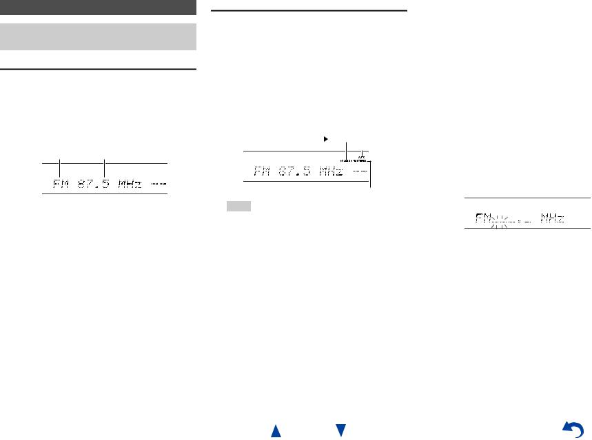
Listening to AM/FM Radio
This section describes the procedure of using the buttons on the front panel, unless otherwise specified.
Using the Tuner
With the built-in tuner you can enjoy AM and FM radio stations. You can store your favorite stations as presets for quick selection.
You can also change the frequency steps ( page 59).
1 Press AM or FM to select either “AM” or “FM”.
In this example, FM has been selected.
Band Frequency
(Actual display depends on the country.)
Tuning into Radio Stations
■Auto tuning mode
1 Press TUNING MODE so that the AUTO indicator lights on the AV receiver’s display.
2 Press TUNING q/w.
Searching stops when a station is found.
When tuned into a station, the TUNED indicator lights. When tuned into a stereo FM station, the FM STEREO indicator lights as shown.
TUNED
AUTO
FM STEREO
Tip
•Tuning into weak FM stereo stations
If the signal from a stereo FM station is weak, it may be impossible to get good reception. In this case, switch to manual tuning mode and listen to the station in mono.
Turning On & Basic Operations
■Manual tuning mode
In manual tuning mode, FM stations will be in mono.
1 |
Press TUNING MODE so that the AUTO indicator |
|
goes off on the AV receiver’s display. |
2 |
Press and hold TUNING q/w. |
|
The frequency stops changing when you release the |
|
button. |
Press the buttons repeatedly to change the frequency one step at a time.
■Tuning into stations by frequency
You can tune into AM and FM stations directly by entering the appropriate frequency.
1 On the remote controller, press AM or FM to select “AM” or “FM”, followed by D.TUN.
(Actual display depends on the country.)
2 Within 8 seconds, use the number buttons to enter the frequency of the radio station.
For example, to tune to 87.5 (FM), press 8, 7, 5 or 8,
7, 5, 0.
If you have entered the wrong number, you can retry after 8 seconds.
En-30
Loading...