


 Loading...
DVD Player
DV-SP402E
Instruction Manual
Thank you for purchasing the Onkyo DVSP402E DVD Player. Read this manual carefully before using your new DVD Player. A good understanding of its features and operation will allow you to achieve optimum performance and enjoyment.
Keep this manual for future reference.
Contents
Important Safety Instructions ............ |
2 |
Introduction ......................................... |
7 |
Connecting the DV-SP402E .............. |
16 |
Getting Started .................................. |
23 |
Playing discs ..................................... |
28 |
Audio Settings and Video Adjust |
|
menus .............................................. |
38 |
Initial Settings menu ......................... |
40 |
Additional information ...................... |
45 |
Glossary............................................. |
49 |
Troubleshooting |
....................................... 50 |
Specifications.................................... |
53 |
|
E n |
WARNING:
TO REDUCE THE RISK OF FIRE OR ELECTRIC SHOCK, DO NOT EXPOSE THIS APPARATUS TO RAIN OR MOISTURE.
CAUTION:
TO REDUCE THE RISK OF ELECTRIC SHOCK, DO NOT REMOVE COVER (OR BACK). NO USER-SERVICEABLE PARTS INSIDE. REFER SERVICING TO QUALIFIED SERVICE PERSONNEL.
WARNING |
|
AVIS |
RISK OF ELECTRIC SHOCK |
|
RISQUE DE CHOC ELECTRIQUE |
DO NOT OPEN |
|
NE PAS OUVRIR |
The lightning flash with arrowhead symbol, within an equilateral triangle, is intended to alert the user to the presence of uninsulated “dangerous voltage” within the product’s enclosure that may be of sufficient
magnitude to constitute a risk of electric shock to persons.
The exclamation point within an equilateral triangle is intended to alert the user to the presence of important operating and maintenance (servicing) instructions in the literature accompanying the appliance.
Important Safety Instructions
1.Read these instructions.
2.Keep these instructions.
3.Heed all warnings.
4.Follow all instructions.
5.Do not use this apparatus near water.
6.Clean only with dry cloth.
7.Do not block any ventilation openings. Install in accordance with the manufacturer’s instructions.
8.Do not install near any heat sources such as radiators, heat registers, stoves, or other apparatus (including amplifiers) that produce heat.
9.Do not defeat the safety purpose of the polarized or grounding-type plug. A polarized plug has two blades with one wider than the other. A grounding type plug has two blades and a third grounding prong. The wide blade or the third prong are provided for your safety. If the provided plug does not fit into your outlet, consult an electrician for replacement of the obsolete outlet.
10.Protect the power cord from being walked on or pinched particularly at plugs, convenience receptacles, and the point where they exit from the apparatus.
11.Only use attachments/accessories specified by the manufacturer.
12. Use only with the cart, stand, tripod, bracket, or table specified by the manufacturer, or sold with the apparatus. When a cart is used, use caution when moving the cart/ apparatus combination to avoid injury from tip-over.
13.Unplug this apparatus during lightning storms or when unused for long periods of time.
14.Refer all servicing to qualified service personnel. Servicing is required when the apparatus has been damaged in any way, such as power-supply cord or plug is damaged, liquid has been spilled or objects have fallen into the apparatus, the apparatus has been exposed to rain or moisture, does not operate normally, or has been dropped.
15.Damage Requiring Service
Unplug the apparatus from the wall outlet and refer servicing to qualified service personnel under the following conditions:
A.When the power-supply cord or plug is damaged,
B.If liquid has been spilled, or objects have fallen into the apparatus,
C.If the apparatus has been exposed to rain or water,
D.If the apparatus does not operate normally by following the operating instructions. Adjust only those controls that are covered by the operating instructions as an improper adjustment of other controls may result in damage and will often require extensive work by a qualified technician to restore the apparatus to its normal operation,
E.If the apparatus has been dropped or damaged in any way, and
F.When the apparatus exhibits a distinct change in performance this indicates a need for service.
16.Object and Liquid Entry
Never push objects of any kind into the apparatus through openings as they may touch dangerous voltage points or short-out parts that could result in a fire or electric shock.
The apparatus shall not be exposed to dripping or splashing and no objects filled with liquids, such as vases shall be placed on the apparatus.
Don’t put candles or other burning objects on top of this unit.
17.Batteries
Always consider the environmental issues and follow local regulations when disposing of batteries.
18.If you install the apparatus in a built-in installation, such as a bookcase or rack, ensure that there is adequate ventilation.
Leave 20 cm (8") of free space at the top and sides and 10 cm (4") at the rear. The rear edge of the shelf or board above the apparatus shall be set 10 cm (4") away from the rear panel or wall, creating a flue-like gap for warm air to escape.
2

Precautions
This unit contains a semiconductor laser system and is classified as a “CLASS 1 LASER PRODUCT”. So, to use this model properly, read this Instruction Manual carefully. In case of any trouble, please contact the store where you purchased the unit.
To prevent being exposed to the laser beam, do not try to open the enclosure.
DANGER:
VISIBLE AND INVISIBLE LASER RADIATION WHEN OPEN AND INTERLOCK FAILED OR DEFEATED. DO NOT STARE INTO BEAM.
CAUTION:
THIS PRODUCT UTILIZES A LASER. USE OF CONTROLS OR ADJUSTMENTS OR PERFORMANCE OF PROCEDURES OTHER THAN THOSE SPECIFIED HEREIN MAY RESULT IN HAZARDOUS RADIATION EXPOSURE.
The label on the right is applied on the rear panel except for USA and Canadian models.
1.This unit is a CLASS 1 LASER PRODUCT and employs a laser inside the cabinet.
2.To prevent the laser from being exposed, do not remove the cover. Refer servicing to qualified personnel.
For U.S. model
The laser is covered by a housing which prevents exposure during operation or maintenance. However, this product is classified as a Laser Product by CDRH (Center for Devices and Radiological Health) which is a department of the Food and Drug Administration. According to their regulations 21 CFR section 1002.30, all manufactures who sell Laser Products must maintain records of written communications between the manufacturer, dealers and customers concerning radiation safety. If you have any complaints about instructions or explanations affecting the use of this product, please feel free to write to the address on the back page of this manual. When you write us, please include the model number and serial number of your unit.
In compliance with Federal Regulations, the certification, identification and the period of manufacture are indicated on the rear panel.
FCC INFORMATION FOR USER
CAUTION:
The user changes or modifications not expressly approved by the party responsible for compliance could void the user’s authority to operate the equipment.
NOTE:
This equipment has been tested and found to comply with the limits for a Class B digital device, pursuant to Part 15 of the FCC Rules.
These limits are designed to provide reasonable protection against harmful interference in a residential installation. This equipment generates, uses and can radiate radio frequency energy and, if not installed and used in accordance with the instructions, may cause harmful interference to radio communications. However, there is no guarantee that interference will not occur in a particular installation.
If this equipment does cause harmful interference to radio or television reception, which can be determined by turning the equipment off and on, the user is encouraged to try to correct the interference by one or more of the following measures:
•Reorient or relocate the receiving antenna.
•Increase the separation between the equipment and receiver.
•Connect the equipment into an outlet on a circuit different from
•that to which the receiver is connected.
•Consult the dealer or an experienced radio/TV technician for help.
3
Precautions—Continued
For Canadian model
NOTE: This class B digital apparatus complies with Canadian ICES-003.
For models having a power cord with a polarized plug: CAUTION: TO PREVENT ELECTRIC SHOCK, MATCH WIDE BLADE OF PLUG TO WIDE SLOT, FULLY INSERT.
Modèle pour les Canadien
REMARQUE: Cet appareil numérique de la classe B est conforme à la norme NMB-003 du Canada.
Sur les modèles dont la fiche est polarisee: ATTENTION: POUR ÉVITER LES CHOCS ÉLECTRIQUES, INTRODUIRE LA LAME LA PLUS LARGE DE LA FICHE DANS LA BORNE CORRESPONDANTE DE LA PRISE ET POUSSER JUSQU’AU FOND.
For British models
Replacement and mounting of an AC plug on the power supply cord of this unit should be performed only by qualified service personnel.
IMPORTANT
The wires in the mains lead are coloured in accordance with the following code:
Blue: Neutral
Brown: Live
As the colours of the wires in the mains lead of this apparatus may not correspond with the coloured markings identifying the terminals in your plug, proceed as follows:
The wire which is coloured blue must be connected to the terminal which is marked with the letter N or coloured black.
The wire which is coloured brown must be connected to the terminal which is marked with the letter L or coloured red.
IMPORTANT
A 5 ampere fuse is fitted in this plug. Should the fuse need to be replaced, please ensure that the replacement fuse has a rating of 5 amperes and that it is approved by ASTA or BSI to BS1362. Check for the ASTA mark or the BSI mark on the body of the fuse.
IF THE FITTED MOULDED PLUG IS UNSUITABLE FOR THE SOCKET OUTLET IN YOUR HOME THEN THE FUSE SHOULD BE REMOVED AND THE PLUG CUT OFF AND DISPOSED OF SAFELY. THERE IS A DANGER OF SEVERE ELECTRICAL SHOCK IF THE CUT OFF PLUG IS INSERTED INTO ANY 13 AMPERE SOCKET.
If in any doubt, consult a qualified electrician.
For European Models
Declaration of Conformity
We, ONKYO EUROPE ELECTRONICS GmbH LIEGNITZERSTRASSE 6, 82194 GROEBENZELL, GERMANY
declare in own responsibility, that the ONKYO product described in this instruction manual is in compliance with the corresponding technical standards such as EN60065, EN55013, EN55020 and EN61000-3-2, -3-3.
GROEBENZELL, GERMANY
I. MORI
ONKYO EUROPE ELECTRONICS GmbH
1. Region Numbers
The DVD standard uses region numbers to control how discs can be played around the world, the world being divided into six regions. This unit will only play DVD discs that match its region number, which can be found
on its rear panel (e.g., 1 ).
2. About this Manual
This manual explains how to use all of this unit’s functions. Although the DVD standard offers many special features, not all discs use them all, so depending on the disc being played, this unit may not respond to certain functions. See the disc’s sleeve notes for supported features.
When you attempt to use a DVD feature that is not available, this logo may appear onscreen, indicating that the feature is not supported by the current disc or this unit.
3. Recording Copyright
Unless it’s for personal use only, recording copyrighted material is illegal without the permission of the copyright holder.
4. Power
WARNING
BEFORE PLUGGING IN THE UNIT FOR THE FIRST TIME, READ THE FOLLOWING SECTION CAREFULLY.
AC outlet voltages vary from country to country. Make sure that the voltage in your area meets the voltage requirements printed on this unit’s rear panel (e.g., AC 120 V, 60 Hz).
4

Precautions—Continued
5.Never Touch this Unit with Wet Hands
Never handle this unit or its power cord while your hands are wet or damp. If water or any other liquid gets inside this unit, have it checked by your Onkyo dealer.
6.Installing this Unit
•Install this unit in a well-ventilated location. Ensure that there’s adequate ventilation all around
this unit, especially if it’s installed in an audio rack. If the ventilation is inadequate, the unit may overheat, leading to malfunction.
•Do not expose this unit to direct sunlight or heat sources, because its internal temperature may rise, shortening the life of the optical pickup.
•Avoid damp and dusty places, and places subject to vibrations from loudspeakers. Never put the unit on top of, or directly above a loudspeaker.
•Install this unit horizontally. Never use it on its side or on a sloping surface, because it may cause a malfunction.
•If you install this unit near a TV, radio, or VCR, the picture and sound quality may be affected. If this occurs, move this unit away from the TV, radio, or VCR.
7. Care
Occasionally, you should dust this unit all over with a soft cloth. For stubborn stains, use a soft cloth dampened with a weak solution of mild detergent and water. Dry the unit immediately afterwards with a clean cloth. Do not use abrasive cloths, thinners, alcohol, or other chemical solvents, because they may damage the finish or remove the panel lettering.
8. Handling Notes
•If you need to transport this unit, use the original packaging to pack it how it was when you originally bought it.
•Do not use volatile liquids, such as insect sprays, near this unit. Do not leave rubber or plastic items on this unit for a long time, because they may leave marks on the case.
•This unit’s top and rear panels may get warm after prolonged use. This is normal.
•When you’ve finished using this unit, remove all discs and turn off the power.
•If you do not use this unit for a long time, it may not work properly the next time you turn it on, so be sure to use it occasionally.
9. To Obtain a Clear Picture
This unit is a high-tech, precision device. If the lens on the optical pickup, or the disc drive mechanism becomes dirty or worn, the picture quality may be affected. To maintain the best picture quality, we recommend regular inspection and maintenance (cleaning or worn part replacement) every 1,000 hours of use depending on the operating environment. Contact your Onkyo dealer for details.
10. Moisture Condensation
Moisture condensation may damage this unit.
Read the following carefully:
When you take a glass containing a cold drink outside on a summer’s day, drops of water, called condensation, form on the outside of the glass. Similarly, moisture may condense on the lens of the optical pickup, one of the most important parts inside this unit.
•Moisture condensation can occur in the following situations:
—The unit is moved from a cold place to a warm place.
—A heater is turned on, or cold air from an air conditioner is hitting the unit.
—In the summer, when this unit is moved from an air conditioned room to a hot and humid place.
—The unit is used in a humid place.
•Do not use this unit when there’s the possibility of moisture condensation occurring. Doing so may damage your discs and certain parts inside this unit.
If condensation does occur, remove all discs and leave this unit turned on for two to three hours. By this time, the unit will have warmed up and any condensation will have evaporated. To reduce the risk of condensation, keep this unit connected to a wall outlet.
5
Table of Contents
Basic Operation |
|
|
Overview |
|
|
Important Safety Instructions.............................. |
2 |
|
Precautions ........................................................ |
|
3 |
Introduction......................................................... |
|
7 |
Supplied Accessories ..................................... |
7 |
|
DV-SP402E Features ..................................... |
7 |
|
Disc Notes ...................................................... |
|
8 |
Before Using the DV-SP402E .......................... |
10 |
|
Installing the Batteries .................................. |
10 |
|
Using the Remote Controller ........................ |
10 |
|
Front & Rear Panels ......................................... |
11 |
|
Front Panel ................................................... |
|
11 |
Display.......................................................... |
|
12 |
Rear Panel.................................................... |
|
13 |
Remote Controller ........................................ |
14 |
|
Connections |
|
|
Connecting the DV-SP402E............................. |
16 |
|
Before Making Any Connections .................. |
16 |
|
AV Cables & Connectors.............................. |
16 |
|
Basic Setup .................................................. |
|
17 |
Connecting Your TV ..................................... |
19 |
|
Connecting to an AV Receiver ..................... |
20 |
|
Connecting |
-compatible Components .... |
21 |
Connecting the Power/Turning on |
|
|
the DV-SP402E |
............................................ |
22 |
Getting Started and Setting up |
|
|
Getting Started ................................................. |
|
23 |
Using the on-screen displays ....................... |
23 |
|
Setting up the player for your TV.................. |
23 |
|
Setting the language of this player’s |
|
|
on-screen displays ..................................... |
24 |
|
Basic Playback |
|
|
Playing discs................................................. |
|
24 |
Basic playback controls ................................ |
25 |
|
Resume and Last Memory ........................... |
26 |
|
DVD-Video disc menus ................................ |
26 |
|
Video CD PBC menus .................................. |
27 |
|
Advanced Operation |
|
Playback Techniques |
|
Playing discs ..................................................... |
28 |
Scanning discs .............................................. |
28 |
Playing in slow motion................................... |
28 |
Frame advance/frame reverse ...................... |
29 |
Viewing a JPEG slideshow ........................... |
29 |
Browsing video content with the |
|
Disc Navigator ............................................ |
30 |
Browsing WMA, MP3 and JPEG files |
|
with the Disc Navigator............................... |
31 |
Looping a section of a disc............................ |
32 |
Using repeat play .......................................... |
32 |
Using random play ........................................ |
33 |
Creating a program list.................................. |
34 |
Other functions available from the |
|
program menu ............................................ |
35 |
Searching a disc............................................ |
35 |
Switching subtitles......................................... |
36 |
Switching audio language/channel................ |
36 |
Zooming the screen ...................................... |
37 |
Switching camera angles .............................. |
37 |
Displaying disc information ........................... |
37 |
Detailed Settings |
|
Audio Settings and Video Adjust menus........... |
38 |
Audio Settings menu ..................................... |
38 |
Audio DRC .................................................... |
38 |
Video Adjust menu ........................................ |
39 |
Initial Settings menu.......................................... |
40 |
Using the Initial Settings menu...................... |
40 |
Digital Audio Out settings.............................. |
41 |
Video Output settings.................................... |
41 |
Language settings......................................... |
42 |
Display settings ............................................. |
42 |
Parental Lock ................................................ |
43 |
Registering a new password ......................... |
43 |
Changing your password .............................. |
43 |
Setting/changing the Parental Lock .............. |
43 |
Setting/changing the Country code ............... |
44 |
Country code list ........................................... |
44 |
Miscellaneous information |
|
Additional information ....................................... |
45 |
Screen sizes and disc formats ...................... |
45 |
Resetting the player ...................................... |
45 |
Setting the TV system ................................... |
46 |
Titles, chapters and tracks ............................ |
46 |
DVD-Video regions ....................................... |
46 |
Selecting languages using the language |
|
code list ...................................................... |
47 |
Language code list ........................................ |
48 |
Glossary............................................................ |
49 |
Troubleshooting ................................................ |
50 |
Specifications.................................................... |
53 |
6
Introduction
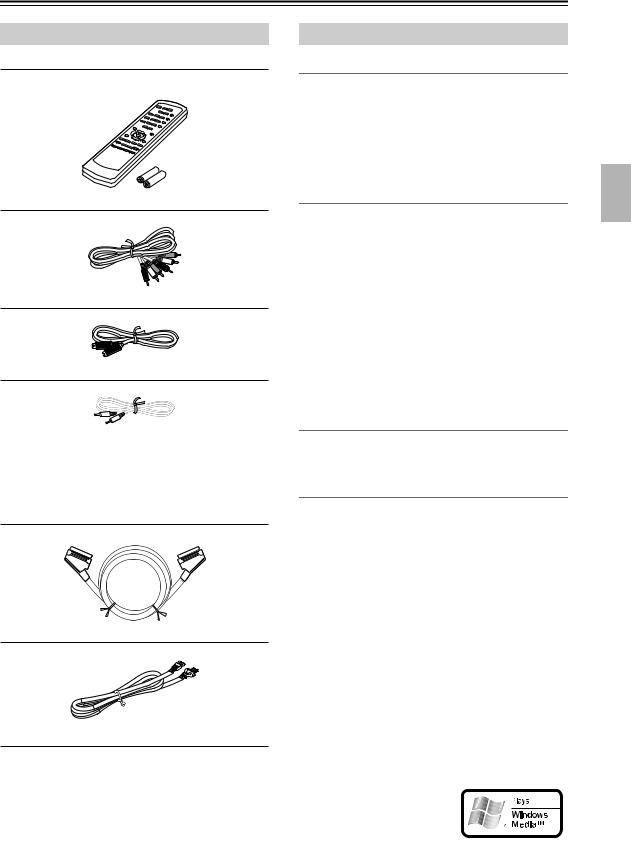
Supplied Accessories
Make sure you have the following accessories:
RC-574DV
Remote controller & 2 batteries (AA)
AV cable (RCA/phono) (1.5 m)
S-Video cable (1.5 m)

 cable (0.8 m)
Cable used for system connections to an Onkyo component with an 
 jack.
jack.
(The components will not function as a system with only 
 connections. Be sure to connect the audio connection cables correctly as well.)
SCART cable (1.5 m)
Power cord (2 m)
DV-SP402E Features
Highlights
•Dolby*1 Digital and DTS*2
•DVD-Video / Video CD / Audio CD playback
•CD-R, CD-RW (Video CD, audio CD, MP3/WMA*3/ JPEG)
•DVD-R (DVD-Video)
•DVD-RW (DVD-Video, VR format)
Video
•Advanced 54 MHz/10-bit video D/A converter
•Component video output
•S-Video and composite video outputs
•Frame-by-frame playback
•Slow motion playback
•Fast forward and reverse
•Repeat playback
•Random playback
•Supports 4:3 and 16:9 aspect ratio TVs
•Multiple camera angle support
•Parental Lock function
•Screen Saver function
Audio
•192 kHz/24-bit D/A converter
•Optical / Coaxial digital output
Others
•Dynamic Range Control setting
•Adjustable display brightness
•Full-function remote controller
The letter displayed at the end of the product name found in catalogs and on package represents the color of the DV-SP402E DVD player. Though the color varies, the specifications and operations are the same.
*1. Manufactured under license from Dolby Laboratories. “Dolby” and the double-D symbol are trademarks of Dolby Laboratories.
*2. “DTS” and “DTS Digital Out” are trademarks of Digital Theater Systems, Inc.
*3. Windows Media, and the Win-
dows logo are trademarks, or
registered trademarks of Microsoft Corporation in the United States and/or other coun-
tries.
7
Introduction—Continued
Disc Notes
Supported Discs
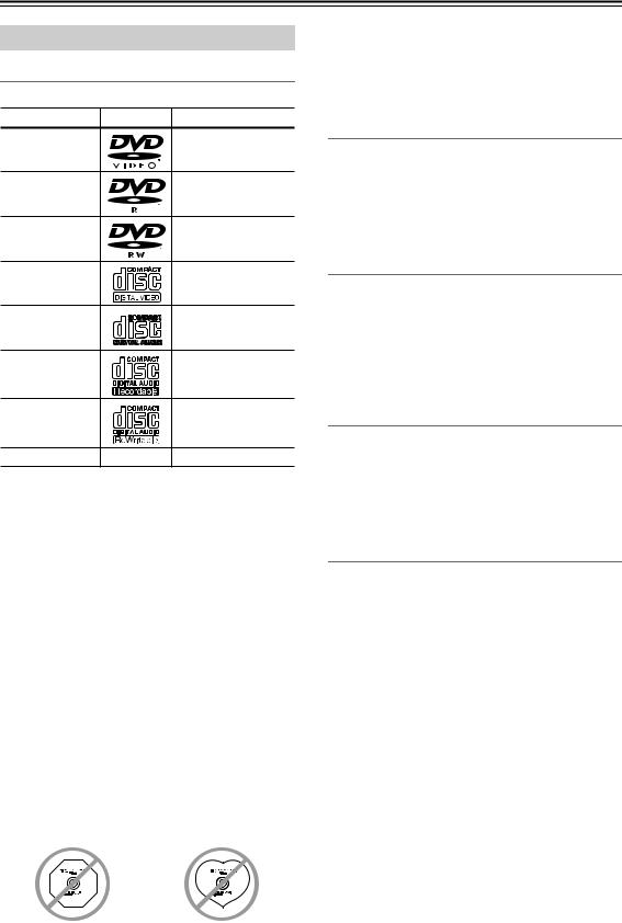
The DV-SP402E supports the following discs.
Disc |
Logo |
Format or file type |
DVD-Video |
|
See page 46 for |
|
region information. |
|
DVD-R |
|
DVD-Video |
|
|
|
DVD-RW |
|
DVD-Video, |
|
VR format |
|
Video CD |
|
Including PBC |
|
|
|
Audio CD |
|
PCM and DTS |
|
|
|
|
|
Video CD, audio CD, |
CD-R |
|
MP3, WMA, JPEG |
|
|
Video CD, audio CD, |
CD-RW |
|
MP3, WMA, JPEG |
JPEG CD |
|
JPEG |
•Some audio CDs feature copy protection that doesn’t conform to the official CD standard. Since these are nonstandard discs, they may not play properly in the DV-SP402E.
•The DV-SP402E supports CD-R and CD-RW discs recorded in Video CD format, audio CD format, or ISO 9660 Level 1 or 2 format with MP3, WMA, and JPEG files. It also supports DVD-R and DVD-RW discs recorded in DVD-Video format. However, some CD-R, CD-RW, DVD-R, and DVD-RW discs may not work properly for any of the following reasons: incomplete disc finalization, disc burner characteristics, disc characteristics, the disc is damaged or dirty. See the manual supplied with your disc burner for more information. Condensation or dirt on the optical pickup lens can also affect playback.
•The DV-SP402E supports 8 cm and 12 cm discs.
•The DV-SP402E does not support disc types not listed.
•Don’t use discs with an unusual shape, such as those shown below, because you may damage the DV-SP402E.
•Don’t use discs that have residue from adhesive tape, rental discs with peeling labels, or discs with custommade labels or stickers. Doing so may damage the DV-SP402E and you may not be able to remove the disc properly.
Discs Made on Personal Computers
Discs made on personal computers, including those of a compatible format, may not work properly in the DV-SP402E because of incorrect settings in the disc burning software. Check the manuals supplied with your disc burning software for additional compatibility information.
CD-R/RW compatibility
•Compatible formats: CD-Audio, Video CD, ISO 9660 CD-ROM* containing MP3, WMA or JPEG files
*ISO 9660 Level 1 or 2 compliant. CD physical format: Mode1, Mode2 XA Form1. Romeo and Joliet file systems are both compatible with this player.
•Multi-session playback: No
•Unfinalized disc playback: No
DVD-R/RW compatibility
•Compatible formats: DVD-Video, Video Recording (VR)*
*Edit points may not play exactly as edited; screen may go momentarily blank at edited points.
•Unfinalized playback: No
•WMA/MP3/JPEG file playback on DVD-R/RW: No
Compressed audio compatibility
•Compatible formats: MPEG-1 Audio Layer 3 (MP3), Windows Media Audio (WMA)
•Sampling rates: 32, 44.1 or 48kHz
•Bit-rates: Any (128Kbps or higher recommended)
•VBR (variable bit rate) MP3 playback: No
•VBR WMA playback: No
•WMA lossless encoding compatible: No
•DRM (Digital Rights Management) compatible: Yes (DRM-protected audio files will not play in this player—see also DRM in the “Glossary” on page 49)
•File extensions: .mp3, .wma (these must be used for the player to recognize MP3 and WMA files – do not use for other file types)
•File structure: Up to 299 folders; up to 648 folders and files combined
8
Introduction—Continued
About WMA
WMA is an acronym for Windows Media Audio and refers to an audio compression technology developed by Microsoft Corporation. WMA content can be encoded by using Windows Media® Player version 7, 7.1, Windows Media® Player for Windows® XP, or Windows Media® Player 9 Series.
JPEG file compatibility
•Compatible formats: Baseline JPEG and EXIF 2.2* still image files up to a resolution of 3072 x 2048.
*File format used by digital still cameras
•Progressive JPEG compatible: No
•File extensions: .jpg (must be used for the player to recognize JPEG files – do not use for other file types)
•File structure: Up to 299 folders; up to 648 folders and files combined
PC-created disc compatibility
Discs recorded using a personal computer may not be playable in this unit due to the setting of the application software used to create the disc. In these particular instances, check with the software publisher for more detailed information.
Discs recorded in packet write mode (UDF format) are not compatible with this player.
Check the DVD-R/RW or CD-R/RW software disc boxes for additional compatibility information.
Copyright
It is forbidden by law to copy, broadcast, show, broadcast on cable, play in public, or rent copyrighted material without permission.
DVD-Video discs are copy-protected, and any recordings made from these discs will be distorted.
This product incorporates copyright protection technology that is protected by method claims of certain U.S. patents and other intellectual property rights owned by Macrovision Corporation and other rights owners. Use of this copyright-protection technology must be authorized by Macrovision Corporation, and is intended for home and other limited viewing uses only, unless otherwise authorized by Macrovision Corporation. Reverse engineering or disassembly is prohibited.
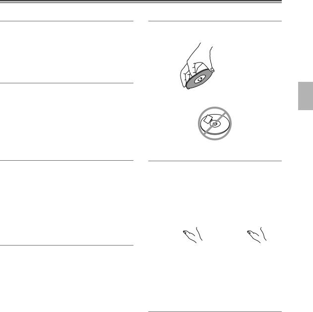
Handling Discs
•Never touch the underside of a disc. Always hold discs by the edge, as shown.
 Underside
• Never attach adhesive tape or sticky labels to discs.
Cleaning Discs
•For best results, keep your discs clean. Fingerprints and dust can affect the sound and picture quality and should be removed as follows. Using a clean soft cloth, wipe from the center outwards, as shown. Never wipe in a circular direction.


•To remove stubborn dust or dirt, wipe the disc with a damp soft cloth, and then dry it with a dry cloth.
•Never use solvent-based cleaning fluids, such as thinner or benzine, commercially available cleaners, or antistatic sprays intended for vinyl records, because they may damage the disc.
Storing Discs
•Don’t store discs in places subject to direct sunlight, or near heat sources.
•Don’t store discs in places subject to moisture or dust, such as in a bathroom or near a humidifier.
•Always store discs in their cases and vertically. Stacking, or putting objects on unprotected discs may cause warping, scratches, or other damage.
9
Before Using the DV-SP402E
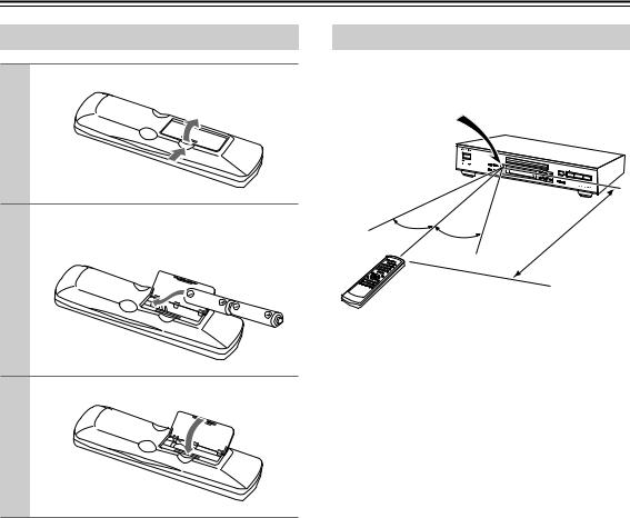
Installing the Batteries
1 Open the battery compartment, as shown.
2 Insert the two supplied batteries (AA) in accordance with the polarity diagram inside the battery compartment.
3 Close the battery compartment.
Notes:
•The supplied batteries should last for about six months, although this will vary with usage.
•If the remote controller doesn’t work reliably, try replacing both batteries.
•Don’t mix new and old batteries, or different types of batteries.
•If you intend not to use the remote controller for a long time, remove the batteries to prevent possible leakage and corrosion.
•Flat batteries should be removed as soon as possible to prevent possible leakage and corrosion.
Using the Remote Controller
To use the remote controller, point it at the DV-SP402E’s remote control sensor, as shown below.
Remote control sensor
DV-SP402E
30˚ |
30˚ |
|
|
m) |
|
|
(5 |
||
|
|
|
||
|
|
|
|
|
|
|
. |
|
|
|
|
Approx |
|
|
Notes:
•The remote controller may not work reliably if the DV-SP402E is subjected to bright light, such as direct sunlight or inverter-type fluorescent lights. Keep this in mind when installing the DV-SP402E.
•If another remote controller of the same type is used in the same room, or the DV-SP402E is installed close to equipment that uses infrared rays, the remote controller may not work reliably.
•Don’t put anything, such as a book, on the remote controller, because the buttons may be pressed inadvertently, thereby draining the batteries.
•The remote controller may not work reliably if the DV-SP402E is installed in a rack behind colored glass doors. Keep this in mind when installing the DV-SP402E.
•The remote controller will not work if there’s an obstacle between it and the DV-SP402E’s remote control sensor.
10
Front & Rear Panels
For detailed information, refer to the pages in brackets.
Front Panel
1 2 |
3 4 5 |
6 |
7 8 9 J K L M |
R Q
ASTANDBY/ON button [22, 24]
This button is used to set the DV-SP402E to On or Standby.
BSTANDBY indicator [22]
This indicator lights up when the DV-SP402E is in Standby.
CDISPLAY button [37]
This button is used to display information about the current disc, title, chapter, or track, including the elapsed time, remaining time, total time, and so on. Press it repeatedly to display more information.
DPLAY MODE button [32–35]
This button is used to open and close the Play Mode menu.
ERemote control sensor [10]
This sensor receives control signals from the remote controller.
FDisc tray [24]
Discs are loaded here.
GTOP MENU button [26]
This button is used to display the top menu of a DVD-Video disc.
HCursor /
/ /
/ /
/ & ENTER buttons [23]
The four cursor buttons located around the central [ENTER] button are used to navigate DVD-Video menus and the onscreen setup menus.
The central [ENTER] button is used to start playback of the selected title, chapter, or track and to confirm settings.
IMENU button [26]
TOP MENU |
|
RS |
OR |
MENU |
|
CU |
|
||
RETURN |
|
|
|
SETUP |
|
PU |
|
ER |
|
|
|
SH TO ENT |
|
|
P O N
J  (open/close) button [24]
This button is used to open and close the disc tray.
K 
 (pause) button [25]
This button is used to pause playback.
L  (stop) button [25]
This button is used to stop playback.
M  (play) button [24, 25]
This button is used to start playback.
N Previous/Next  /
/
 buttons [25]
The Previous button is used to select the previous chapter or track. During playback it selects the beginning of the current chapter or track.
The Next button is used to select the next chapter or track.
OSETUP button [23]
This button is used to open and close the onscreen setup menus.
PRETURN button [23, 26]
This button is used to return to the main menu without saving your changes.
QCLEAR button [34]
This button is used to cancel various functions.
RDIMMER button
This button is used to adjust the display brightness.
normal dim dimmer
This button is used to display a menu on a DVD-Video disc or to open the Disc Navigator when using a Video CD, audio CD, WMA/MP3/ JPEG disc, or VR format DVD-RW disc.
11
Front & Rear Panels—Continued
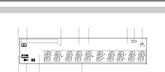
Display
1 |
2 |
3 |
4 |
5 |
6 7 8 |
DVD |
V CD |
GUI |
|
D |
TITLE |
TRACK CHP |
REMAIN |
PROGRESSIVE |
|
|
|
9 0 A B |
C |
1 
 D indicator
This indicator appears when playing Dolby Digital material.
2Disc type indicators
These indicators show the type of disc loaded.
3 TITLE indicator
While stopped, the total number of titles on the current DVD-Video disc is displayed here. During playback, the number of the current title is displayed.
4TRACK indicator
This indicator appears while track numbers are being displayed. While stopped, the total number of tracks on the current Video CD, audio CD, or MP3/ WMA disc are displayed. During playback, the number of the current track is displayed.
5 CHP indicator
9DTS indicator
This indicator appears when playing DTS material.
0Play  indicator
This indicator is shown during playback.
APause 
 indicator
This indicator appears when playback is paused.
BPROGRESSIVE indicator
This indicator appears when the Progressive Scanning function is on.
CMessage & time area
Time information, such as total time, remaining time, and so on, is displayed here in hours, minutes, and seconds. Other messages are also displayed.
This indicator appears while the number of the current chapter is being displayed.
6REMAIN indicator
This indicator appears while the remaining time is being displayed.
7Repeat  indicator
This indicator appears when A–B playback or repeat playback is used.
8Camera angle  indicator
This indicator appears if the DVD-Video disc being played features multiple camera angles.
12
Front & Rear Panels—Continued
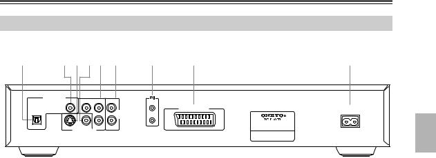
Rear Panel
1 |
2 3 45 6 |
7 |
8 |
9 |
|||
|
AUDIO OUTPUT |
|
COMPONENT |
REMOTE |
|
|
|
|
DIGITAL |
|
|
|
|||
|
Y |
PB |
L |
|
|
||
|
|
CONTROL |
|
|
|||
OPTICAL |
COAXIAL |
|
|
AUDIO |
|
AV CONNECTOR |
AC INLET |
|
|
|
|
|
|
|
|
|
|
|
|
OUTPUT |
|
|
|
|
|
|
|
ANALOG |
|
|
|
|
|
|
|
R |
|
|
MODEL NO. DV-SP402E |
|
|
S VIDEO |
VIDEO |
|
|
|
|
|
|
PR |
|
|
|
||
VIDEO OUTPUT
AOPTICAL DIGITAL AUDIO OUTPUT [20]
This optical digital audio output can be connected to an optical digital audio input on a hi-fi amp, AV receiver, or surround sound decoder (Dolby Digital, DTS).
BCOAXIAL DIGITAL AUDIO OUTPUT [20]
This coaxial digital audio output can be connected to a coaxial digital audio input on a hi-fi amp, AV receiver, or surround sound decoder (Dolby Digital, DTS).
CS VIDEO OUTPUT [19]
This connector can be used to connect a TV or projector with an S-Video input.
DVIDEO OUTPUT [17]
This RCA/phono connector can be used to connect a TV or projector with a composite video input.
ECOMPONENT VIDEO OUTPUT [19]
These sockets output component video and can be connected to an component video input on a TV or projector.
FANALOG AUDIO OUTPUT [17]
G
 jack [21]
These 
 (Remote Interactive) connectors can be connected to the
 connectors on your other Onkyo AV components for interactive control. Connecting an
 cable only does not make the system operational. You must also connect the audio cables as well.
HAV CONNECTOR [19]
This SCART output can be connected to a TV or projector with a SCART input by using the supplied SCART cable. This SCART connector outputs 2- channel stereo audio, composite video, S-Video, and RGB video.
IAC INLET [22]
The supplied power cord is connected here. The other of the power cord should be connected to a suitable wall outlet.
These RCA/phono connectors can be connected to analog audio inputs on your TV, hi-fi amp, or AV receiver.
13
Front & Rear Panels—Continued
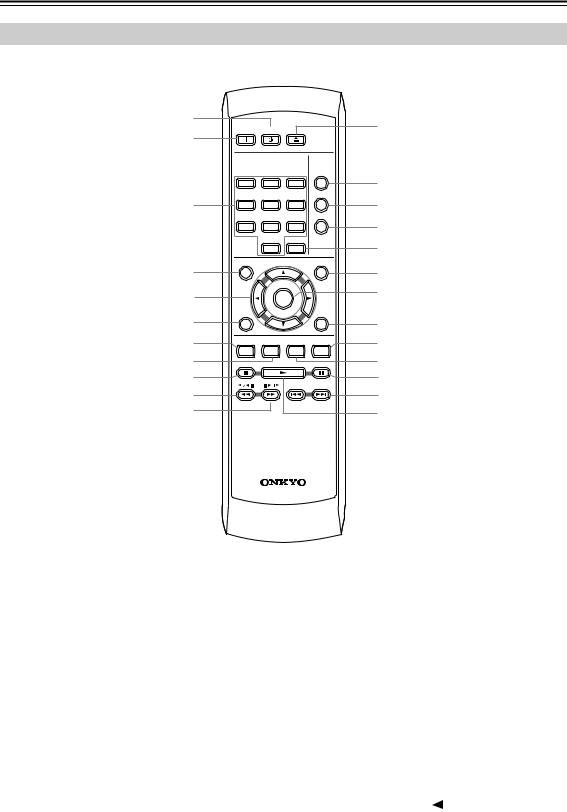
Remote Controller
1
2
3
ON |
STANDBY |
|
|
|
OPEN/ |
|
|
CLOSE |
|
|
PLAY |
|
|
MODE |
1 |
2 |
3 |
|
|
DISPLAY |
4 |
5 |
6 |
|
|
DIMMER |
7 |
8 |
9 |
|
0 |
CLEAR |
L
M N O P
|
TOP MENU |
MENU |
|
4 |
|
|
Q |
5 |
|
ENTER |
R |
|
|
||
6 |
RETURN |
SETUP |
|
|
|
S |
|
7 |
AUDIO |
ANGLE SUBTITLE ZOOM |
T |
8 |
|
|
U |
9 |
|
|
V |
J |
|
|
W |
K |
|
|
X |
RC-574DV
A STANDBY button [22] |
F RETURN button [23, 26] |
This button is used to set the DV-SP402E to Standby.
BON button [22]
This button is used to turn on the DV-SP402E. Don’t turn on the DV-SP402E until you’ve completed, and double checked all connections (pages 16–21).
CNumber buttons [25–27, 35, 43]
These buttons are used to enter title, chapter, and track numbers and to enter times for locating specific points in time.
DTOP MENU button [26]
This button is used to display the top menu on a DVD-Video disc.
ECursor /
/ /
/ /
/ buttons [23]
These buttons are used to navigate onscreen menus.
This button is used to return to the main menu without saving your changes.
GAUDIO button [36]
This button is used to select foreign language soundtracks and audio formats (e.g., Dolby Digital or DTS) on DVD-Video discs.
For Video CDs you can select left-channel, rightchannel, or stereo.
HANGLE button [37]
This button is used to select camera angles on DVD-Video discs.
IStop  button [27]
This button is used to stop playback.
JFast Reverse / (
/ ( 


 ) button [25, 28, 29]
This button is used for fast reverse, reverse slow motion, and reverse frame-by-frame playback.
14

Front & Rear Panels—Continued
KFast Forward  / (
/ (


 ) button [25, 28, 29]
This button is used for fast forward, slow motion, and frame-by-frame playback.
LOPEN/CLOSE  button [24]
This button is used to open and close the disc tray.
MPLAY MODE button [32–35]
This button is used to open and close the Play Mode menu.
NDISPLAY button [37]
This button is used to display information about the current disc, title, chapter, or track, including the elapsed time, remaining time, total time, and so on. Press it repeatedly to display more information.
ODIMMER button
This button is used to adjust the display brightness.
normal dim dimmer
PCLEAR [34]
This button is used to cancel various functions.
QMENU button [26]
This button is used to display the menu on a DVD-Video disc or to open the Disc Navigator when using a Video CD, audio CD, WMA/MP3/ JPEG disc, or VR format DVD-RW disc.
RENTER button [23]
This button is used to start playback of the selected title, chapter, or track, and to confirm settings.
SSETUP button [24, 38–40]
This button is used to open and close the onscreen setup menus.
TZOOM button [37]
This button is used with the Zoom function.
USUBTITLE button [36]
This button is used to select subtitles on DVD-Video discs.
VPause 
 button [25, 28, 29]
This button is used to pause playback.
WPrevious/Next  /
/
 buttons [25]
The Previous button is used to select the previous chapter or track. During playback it selects the beginning of the current chapter or track.
The Next button is used to select the next chapter or track.
XPlay  button [25]
This button is used to start playback.
15

Connecting the DV-SP402E
Before Making Any Connections
•Read the manuals supplied with your AV components.
•Don’t connect the power cord until you’ve completed all audio and video connections.
Optical Digital Inputs
The DV-SP402E’s optical digital connectors have a shut- ter-type cover that opens when an optical plug is inserted, and closes when it’s removed. Push the plug in all the way.
RCA/phono AV Connection Color Coding
RCA/phono AV connections are usually color coded: red, white, and yellow. Use red plugs to connect rightchannel audio inputs and outputs (typically labeled “R”). Use white plugs to connect left-channel audio inputs and outputs (typically labeled “L”). And use yellow plugs to connect composite video inputs and outputs.
|
Analog audio |
Right (red) |
Right (red) |
Left (white) |
Left (white) |
|
Composite video |
(Yellow)
•Push each plug in all the way to make a good connection (loose connections can cause noise or malfunctions).
•To prevent interference, keep audio and video cables away from power cords and speaker cables.
 (Yellow)
 Right!
 Wrong!
AV Cables & Connectors
Video
|
PR / CR |
PR / CR |
|
Component video separates the luminance (Y) and |
|
|
color difference signals (PR, PB), providing the best |
||
Component |
|
|
|
|
|
Y |
PB |
PR |
|
video |
PB /CB |
PB / CB |
|
picture quality. Some TV manufacturers label their |
|
|
|
||
Y |
Y |
|
component video inputs differently. |
|
|
|
|||
|
|
|
S VIDEO |
S-Video provides better picture quality than com- |
S-Video |
|
|
|
posite video. |
Composite |
|
|
VIDEO |
Composite video can be found on virtually all TVs, |
|
|
|
VCRs, and video equipment. |
|
video |
|
|
|
|
|
|
|
|
|
|
|
|
AV CONNECTOR |
SCART connections carry audio and video (com- |
|
|
|
posite, S-Video, RGB) all in one cable. |
|
Scart |
|
|
|
Audio
Optical digital
Coaxial digital
Analog
OPTICAL |
Optical digital audio connections provide better |
|
audio quality than analog connections. |
COAXIAL |
Coaxial digital audio connections provide better |
|
|
|
audio quality than analog connections. |
AUDIO |
|
RCA/phono analog audio connectors can be found |
L |
R |
on virtually all AV components. |
|
|
|
16
Connecting the DV-SP402E—Continued
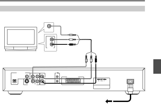
Basic Setup
The setup described here is a basic setup that allows you to play discs using just the cables supplied with the player. In this setup, stereo audio is played through the speakers in your TV.
VIDEO IN
TV
L |
R
ANALOG
INPUT
AUDIO OUTPUT
|
DIGITAL |
|
COMPONENT |
REMOTE |
|
|
Y |
PB |
L |
||
|
|
CONTROL |
|||
OPTICAL |
COAXIAL |
|
|
AUDIO |
AV CONNECTOR |
|
|
|
|
AC INLET |
|
|
|
|
|
OUTPUT |
|
|
|
|
|
ANALOG |
|
|
|
|
|
R |
MODEL NO. DV-SP402E |
|
|
S VIDEO |
VIDEO |
|
|
|
|
PR |
|
||
VIDEO OUTPUT
•This player is equipped with copy protection technology. Do not connect this player to your TV via a VCR using AV cables, as the picture from this player will not appear properly on your TV. (This player may also not be compatible with some combination TV/VCRs for the same reason; refer to the manufacturer for more information.)
•When connecting to your TV as shown above, do not set the “Component Out” setting (page 41) to “Progressive.”
1.Connect the VIDEO OUTPUT and AUDIO OUTPUT ANALOG L/R jacks to a set of A/V inputs on your TV.
Use the supplied AV cable (RCA/phono), connecting the red and white plugs to the audio outputs and the yellow plug to the video output. Make sure you match up the left and right audio outputs with their corresponding inputs for correct stereo sound.
See the following page if you want to use a component or S-Video cable for the video connection.
2.Connect the supplied AC power cord to the AC INLET, then plug into a power outlet.
To power outlet
Notes:
•Before unplugging the player from the power outlet, make sure you first switch it into standby using either the front panel STANDBY/ON button, or the remote controller, and wait of the “GOOD BYE” message to disappear from the player’s display.
•For the above reasons, do not plug this player into a switched power supply found on some amplifiers and AV receivers.
Important:
•When Component Out (page 41) is set to Progressive, there is no video output from the VIDEO OUTPUT (composite) and S VIDEO OUTPUT jacks.
•If you want to display video on more than one monitor simultaneously, make sure the player is set to Interlace.
•If you connect a TV that is not compatible with a progressive scan signal and switch the player to progressive, you will not be able to see any picture at all. In this case, switch everything off and reconnect using the supplied video cable, then switch back to Interlace (see page 18).
17
Loading...