


DR-S2.2

DVD Receiver
DR-S2.2
Instruction Manual
Thank you for purchasing the Onkyo DVD Receiver.
Please read this manual thoroughly before making
connections and turning on the power.
Following the instructions in this manual will enable
you to obtain optimum performance and listening
enjoyment from your new DVD Receiver.
Please retain this manual for future reference.
Contents
Getting Started
Setup
Before Using Your DVD Receiver 2
Other
Advanced Operation
Basic Operation
2
Important Safeguards
1. Read Instructions – All the safety and operating instructions
should be read before the appliance is operated.
2. Retain Instructions – The safety and operating instructions
should be retained for future reference.
3. Heed Warnings – All warnings on the appliance and in the
operating instructions should be adhered to.
4. Follow Instructions – All operating and use instructions should
be followed.
5. Cleaning – Unplug the appliance from the wall outlet (the
mains) before cleaning. The appliance should be cleaned only
as recommended by the manufacturer.
6. Attachments – Do not use attachments not recommended by
the appliance manufacturer as they may cause hazards.
7. Water and Moisture – Do not use the appliance near water –for
example, near a bath tub, wash bowl, kitchen sink, or laundry
tub; in a wet basement; or near a swimming pool; and the like.
8. Accessories – Do not place the appliance on an unstable cart,
stand, tripod, bracket, or table. The appliance may fall, causing
serious injury to a child or adult, and serious damage to the
appliance. Use only with a cart, stand, tripod, bracket, or table
recommended by the manufacturer, or sold with the appliance.
Any mounting of the appliance should follow the manufacturer’s
instructions, and should use a mounting accessory
recommended by the manufacturer.
9. An appliance and cart combination should
be moved with care. Quick stops,
excessive force, and uneven surfaces
may cause the appliance and cart
combination to overturn.
10. Ventilation – Slots and openings in the cabinet are provided for
ventilation and to ensure reliable operation of the appliance and
to protect it from overheating, and these openings must not be
blocked or covered. The openings should never be blocked by
placing the appliance on a bed, sofa, rug, or other similar
surface. The appliance should not be placed in a built-in
installation such as a bookcase or rack unless proper ventilation
is provided. There should be free space of at least 20 cm (8 in.)
and an opening behind the appliance.
11. Power Sources – The appliance should be operated only from
the type of power source indicated on the marking label. If you
are not sure of the type of power supply to your home, consult
your appliance dealer or local power company.
12. Grounding or Polarization – The appliance may be equipped
with a polarized alternating current line plug (a plug having one
blade wider than the other). This plug will fit into the power
outlet only one way. This is a safety feature. If you are unable to
insert the plug fully into the outlet, try reversing the plug. If the
plug should still fail to fit, contact your electrician to replace your
obsolete outlet. Do not defeat the safety purpose of the
polarized plug.
13. Power-Cord Protection – Power-supply cords (mains leads)
should be routed so that they are not likely to be walked on or
pinched by items placed upon or against them, paying particular
attention to cords (leads) at plugs, convenience receptacles, and
the point where they exit from the appliance.
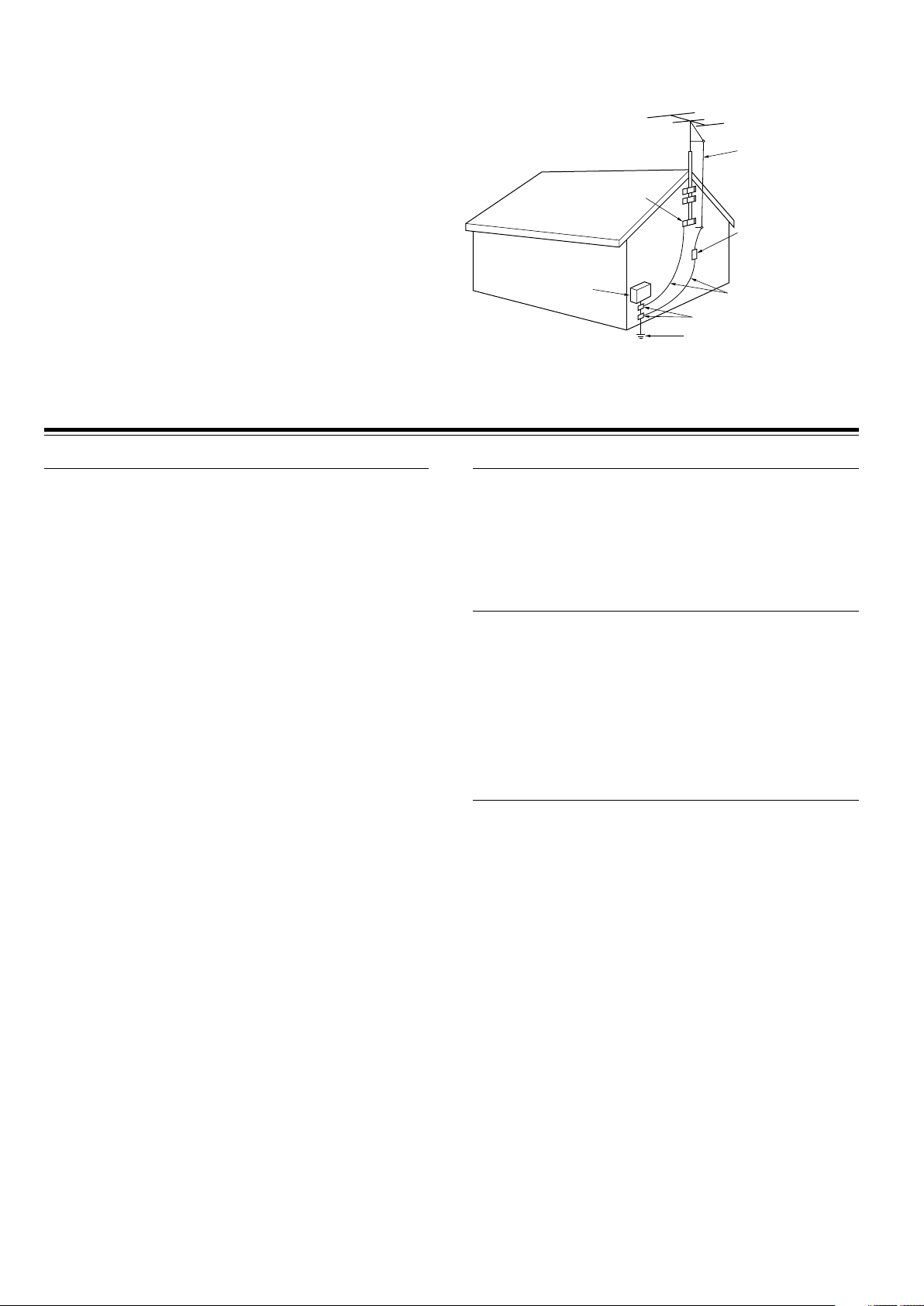
14. Outdoor Antenna (Aerial) Grounding – If an outside antenna (aerial)
or cable system is connected to the appliance, be sure the antenna
(aerial) or cable system is grounded so as to provide some protection
against voltage surges and built-up static charges. Article 810 of the
National Electrical Code, ANSI/NFPA 70, provides information with
regard to proper grounding of the mast and supporting structure,
grounding of the lead-in wire to an antenna- (aerial-) discharge unit,
size of grounding conductors, location of antenna- (aerial-) discharge
unit, connection to grounding electrodes, and requirements for the
grounding electrode. See FIGURE 1.
15. Lightning – For added protection for the appliance during a
lightning storm, or when it is left unattended and unused for long
periods of time, unplug it from the wall outlet (the mains) and
disconnect the antenna (aerial) or cable system. This will prevent
damage to the appliance due to lightning and power-line surges.
16. Power Lines – An outside antenna (aerial) system should not be
located in the vicinity of overhead power lines or other electric light or
power circuits, or where it can fall into such power lines or circuits.
When installing an outside antenna (aerial) system, extreme care
should be taken to keep from touching such power lines or circuits as
contact with them might be fatal.
17. Overloading – Do not overload wall outlets, extension cords
(leads), or integral convenience receptacles as this can result in a
risk of fire or electric shock.
18. Object and Liquid Entry – Never push objects of any kind into the
appliance through openings as they may touch dangerous voltage
points or short-out parts that could result in a fire or electric shock.
Never spill liquid of any kind on the appliance.
19. Servicing – Do not attempt to service the appliance yourself as
opening or removing covers may expose you to dangerous voltage
or other hazards. Refer all servicing to qualified service personnel.
20. Damage Requiring Service – Unplug the appliance form the wall
outlet (the mains) and refer servicing to qualified service personnel
under the following conditions:
A. When the power-supply cord (mains lead) or plug is damaged,
B. If liquid has been spilled, or objects have fallen into the
appliance,
C. If the appliance has been exposed to rain or water,
D. If the appliance does not operate normally by following the
operating instructions. Adjust only those controls that are
covered by the operating instructions as an improper
adjustment of other controls may result in damage and will
often require extensive work by a qualified technician to restore
the appliance to its normal operation,
E. If the appliance has been dropped or damaged in any way, and
F. When the appliance exhibits a distinct change in performance –
this indicates a need for service.
S3125A
PORTABLE CART WARNING
WARNING:
TO REDUCE THE RISK OF FIRE OR ELECTRIC SHOCK,
DO NOT EXPOSE THIS APPLIANCE TO RAIN OR
MOISTURE.
CAUTION:
TO REDUCE THE RISK OF ELECTRIC SHOCK, DO NOT
REMOVE COVER (OR BACK). NO USER-SERVICEABLE
PARTS INSIDE. REFER SERVICING TO QUALIFIED
SERVICE PERSONNEL.
The lightning flash with arrowhead symbol, within an equilateral
triangle, is intended to alert the user to the presence of uninsulated
“dangerous voltage” within the product’s enclosure that may be of
sufficient magnitude to constitute a risk of electric shock to persons.
The exclamation point within an equilateral triangle is intended to alert
the user to the presence of important operating and maintenance
(servicing) instructions in the literature accompanying the appliance.
WARNING
RISK OF ELECTRIC SHOCK
DO NOT OPEN
RISQUE DE CHOC ELECTRIQUE
NE PAS
OUVRIR
AVIS
3
Precautions
For Canadian model
This class B digital apparatus complies with Canadian ICES-003.
For models having a power cord with a polarized plug:
CAUTION: TO PREVENT ELECTRIC SHOCK, MATCH WIDE
BLADE OF PLUG TO WIDE SLOT, FULLY INSERT.
Modèle pour les Canadien
Cet appareil numérique de la classe B est conforme à la norme
NMB-003 du Canada.
Sur les modèles dont la fiche est polarisée:
ATTENTION: POUR ÈVITER LES CHOCS ÉLECTRIQUES,
INTRODUIRE LA LAME LA PLUS LARGE DE LA FICHE DANS LA
BORNE CORRESPONDANTE DE LA PRISE ET POUSSER
JUSQU’AU FOND.
For British model
Replacement and mounting of an AC plug on the power supply cord
of this unit should be performed only by qualified service personnel.
IMPORTANT
The wires in the mains lead are coloured in accordance with the
following code:
Blue: Neutral
Brown: Live
As the colours of the wires in the mains lead of this apparatus may
not correspond with the coloured markings identifying the terminals
in your plug, proceed as follows:
The wire which is coloured blue must be connected to the terminal
which is marked with the letter N or coloured black.
The wire which is coloured brown must be connected to the terminal
which is marked with the letter L or coloured red.
IMPORTANT
A 5 ampere fuse is fitted in this plug. Should the fuse need to be
replaced, please ensure that the replacement fuse has a rating of 5
amperes and that it is approved by ASTA or BSI to BS1362. Check
for the ASTA mark or the BSI mark on the body of the fuse.
IF THE FITTED MOULDED PLUG IS UNSUITABLE FOR THE
SOCKET OUTLET IN YOUR HOME THEN THE FUSE SHOULD BE
REMOVED AND THE PLUG CUT OFF AND DISPOSED OF
SAFELY. THERE IS A DANGER OF SEVERE ELECTRICAL
SHOCK IF THE CUT OFF PLUG IS INSERTED INTO ANY 13
AMPERE SOCKET.
If in any doubt, please consult a qualified electrician.
For U.S. model
The laser is covered by a housing which prevents exposure during
operation or maintenance. However, this product is classified as a
Laser Product by CDRH (Center for Devices and Radiological
Health) which is a department of the Food and Drug Administration.
According to their regulations 21 CFR section 1002.30, all
manufactures who sell Laser Products must maintain records of
written communications between the manufacturer, dealers and
customers concerning radiation safety. If you have any complaints
about instructions or explanations affecting the use of this product,
please feel free to write to the address on the back page of this
manual. When you write us, please include the model number and
serial number of your unit.
In compliance with Federal Regulations, the certification,
identification and the period of manufacture are indicated on the rear
panel.
FCC INFORMATION FOR USER
CAUTION:
The user changes or modifications not expressly approved by the
party responsible for compliance could void the user’s authority to
operate the equipment.
NOTE:
This equipment has been tested and found to comply with the limits
for a Class B digital device, pursuant to Part 15 of the FCC Rules.
These limits are designed to provide reasonable protection against
harmful interference in a residential installation. This equipment
generates, uses and can radiate radio frequency energy and, if not
installed and used in accordance with the instructions, may cause
harmful interference to radio communications. However, there is no
guarantee that interference will not occur in a particular installation.
If this equipment does cause harmful interference to radio or
television reception, which can be determined by turning the
equipment off and on, the user is encouraged to try to correct the
interference by one or more of the following measures:
• Reorient or relocate the receiving antenna.
• Increase the separation between the equipment and receiver.
• Connect the equipment into an outlet on a circuit different from
that to which the receiver is connected.
• Consult the dealer or an experienced radio/TV technician for help.
Note to CATV system installer:
This reminder is provided to call the CATV system installer’s
attention to Article 820-40 of the NEC, ANSI/NFPA 70, which
provides guidelines for proper grounding and, in particular, specifies
that the cable ground shall be connected to the grounding system of
the building, as close to the point of cable entry as practical.
21. Replacement Parts – When replacement parts are required, be
sure the service technician has used replacement parts
specified by the manufacturer or have the same characteristics
as the original part. Unauthorized substitutions may result in
fire, electric shock, or other hazards.
22. Safety Check – Upon completion of any service or repairs to
the appliance, ask the service technician to perform safety
checks to determine that the appliance is in proper operation
condition.
23. Wall or Ceiling Mounting – The appliance should be mounted
to a wall or ceiling only as recommended by the manufacturer.
24. Heat – The appliance should be situated away from heat
sources such as radiators, heat registers, stoves, or other
appliances (including amplifiers) that produce heat.
25. Liquid Hazards – The appliance shall not be exposed to
dripping or splashing and no objects filled with liquids, such as
vases shall be placed on the appliance.
FIGURE 1:
EXAMPLE OF ANTENNA (AERIAL) GROUNDING AS PER NATIONAL
ELECTRICAL CODE, ANSI/NFPA 70
GROUND
CLAMP
ELECTRIC
SERVICE
EQUIPMENT
POWER SERVICE GROUNDING
ELECTRODE SYSTEM
(NEC ART 250, PART H)
GROUND CLAMPS
GROUNDING CONDUCTORS
(NEC SECTION 810-21)
ANTENNA
DISCHARGE UNIT
(NEC SECTION 810-20)
ANTENNA
LEAD IN
WIRE
NEC – NATIONAL ELECTRICAL CODE
S2898A
4
1. Regional Restriction Codes (Region Number)
Regional restriction codes are built into DVD Receivers and DVD
videos for each sales region. If the regional code of the DVD
Receiver does not match one of the regional codes on the DVD
video, playback is not possible.
The regional number can be found on the rear panel of the DVD
Receiver. (e.g.
1
for Region 1)
2. About This Manual
This manual explains the basic procedures for operating the DVD
Receiver. Some DVD videos do not support the full potential of the
DVD technology. Your DVD Receiver may therefore not respond
to all operating commands. Refer to instruction notes on discs.
A “ ” mark may appear on the TV screen during operation. It
means that the operation is not permitted by the DVD Receiver or
the disc.
3. Recording Copyright
Recording of copyrighted material for other than personal use is
illegal without permission of the copyright holder.
4. AC Fuse
The fuse is located inside the chassis and is not user-serviceable.
If power does not come on, contact your Onkyo authorized service
center.
5. Power
WARNING
BEFORE PLUGGING IN THE UNIT FOR THE FIRST TIME, READ
THE FOLLOWING SECTION CAREFULLY.
The voltage of the available power supply differs according to
country or region. Be sure that the power supply voltage of the
area where the unit will be used meets the required voltage (AC
120V 60Hz or AC 230-240V 50Hz) written on the rear panel.
6. Do not touch the unit with wet hands
Do not handle the unit or power cord (mains lead) when your hands
are wet or damp. If water or any other liquid enters the case, take
the unit to an authorized service center for inspection.
Precautions
7. Location of the unit
• Place the unit in a well-ventilated location.
Take special care to provide plenty of ventilation on all sides of
the unit especially when it is placed in an audio rack. If ventilation
is blocked, the unit may overheat and malfunction.
• Do not expose the unit to direct sunlight or heating units as the
unit's internal temperature may rise and shorten the life of the
pickup.
• Avoid damp and dusty places and places directly affected by
vibrations from the speakers. In particular, avoid placing the unit
on or above one of the speakers.
• Be sure the unit is placed in a horizontal position. Never place it
on its side or on a slanted surface as it may malfunction.
• When you place the unit near a TV, radio, or VCR, the playback
picture may become poor and the sound may be distorted. In
this case, place the unit away from the TV, radio, or VCR.
8. Care
From time to time you should wipe the front and rear panels and
the cabinet with a soft cloth. For heavier dirt, dampen a soft cloth
in a weak solution of mild detergent and water, wring it out dry, and
wipe off the dirt. Following this, dry immediately with a clean cloth.
Do not use rough material, thinners, alcohol or other chemical
solvents or cloths since these could damage the finish or remove
the panel lettering.
9. Notes on Handling
• When shipping the unit, use the original shipping carton and
packing materials. For maximum protection, repack the unit as
it was originally packed at the factory.
• Do not use volatile liquids, such as insect spray, near the unit.
Do not leave rubber or plastic products in contact with the unit
for a long time. They will leave marks on the finish.
• The top and rear panels of the unit may become warm after a
long period of use. This is not a malfunction.
• When the unit is not in use, be sure to remove the disc and turn
off the power.
• If you do not use the unit for a long period, the unit may not
function properly in the future. Turn on and use the unit
occasionally.
10. To Obtain a Clear Picture
The unit is a high technology, precision device. If the optical pick-
up lens and disc drive parts are dirty or worn down, the picture
quality becomes poor. To obtain a clear picture, we recommend
regular inspection and maintenance (cleaning or parts
replacement) every 1,000 hours of use depending on the operating
environment. For details, contact your nearest dealer.
11. Notes on Moisture Condensation
Moisture condensation damages the unit.
Please read the following carefully.
• What is moisture condensation?
Moisture condensation occurs, for example, when you pour a
cold drink into a glass on a warm day. Drops of water form on
the outside of the glass. In the same way, moisture may condense
on the optical pick-up lens inside the unit, one of the most crucial
internal parts of the unit.
• Moisture condensation occurs in the following cases.
– When you bring the unit directly from a cold place to a warm
place.
– When you use the unit in a room where you just turned on the
heater, or a place where the cold wind from the air conditioner
directly hits the unit.
– In summer, when you use the unit in a hot and humid place
just after you move the unit from an air conditioned room.
– When you use the unit in a humid place.
• Do not use the unit when moisture condensation may occur.
If you use the unit in such a situation, it may damage discs and
internal parts. Remove the disc, connect the power cord (mains
lead) of the unit to the wall outlet (the mains), turn on the unit,
and leave it for two or three hours. After a few hours, the unit will
have warmed up and evaporated any moisture. Keep the unit
connected to the wall outlet (the mains) and moisture
condensation will seldom occur.
CAUTION:
VISIBLE LASER RADIATION WHEN OPEN AND INTERLOCK
FAILED OR DEFEATED. DO NOT STARE INTO BEAM.
CAUTION:
THIS PRODUCT UTILIZES A LASER. USE OF CONTROLS OR
ADJUSTMENTS OR PERFORMANCE OF PROCEDURES
OTHER THAN THOSE SPECIFIED HEREIN MAY RESULT IN
HAZARDOUS RADIATION EXPOSURE.
This unit contains a semiconductor laser system and is classified
as a “CLASS 1 LASER PRODUCT.” So, to use this model properly,
read this Instruction Manual carefully. In case of any trouble,
please contact the store where you purchased the unit. To prevent
being exposed to the laser beam, do not try to open the enclosure.
For European model
“CLASS 1 LASER
PRODUCT ”
This label on the rear panel states that:
1. This unit is a CLASS 1 LASER PRODUCT and employs a
laser inside the cabinet.
2. To prevent the laser from being exposed, do not remove the
cover. Refer servicing to qualified personnel.

5
Table of Contents
Important Safeguards/Precautions/Table of Contents .................................... 2/3/5
Getting Started
Features ................................................................................................................ 6
Supplied Accessories ............................................................................................ 7
Notes on Discs ...................................................................................................... 8
Index to Parts and Controls ................................................................................ 10
Preparing the Remote Controller ........................................................................ 15
Connecting to a TV (Other than European model).............................................. 16
Connecting to a TV (European model)................................................................ 17
Connecting Speakers (North American and South American model) ................. 18
Connecting Speakers (Other models)................................................................. 19
Positioning Speakers .......................................................................................... 20
Connecting to Audio/Video Equipment................................................................ 21
z Connection for the Onkyo MD Recorder or Cassette Tape Deck .................. 23
Making Antenna (Aerial) Connections................................................................. 24
Setup
Connecting the Power/Turning on the DVD Receiver......................................... 26
Setting Up the DVD Receiver ............................................................................. 27
Speaker Setup .................................................................................................... 29
Basic Operation
Getting Started Using Your DVD Receiver .......................................................... 34
Listening to the Radio ......................................................................................... 38
Playing the Connected Source ........................................................................... 40
Various Functions Common to all the Sources ................................................... 42
Enjoying the Sound Effects ................................................................................. 44
Advanced Operation
Still Frame/Slow Play .......................................................................................... 51
Locating a Specific Title/Folder/Chapter/Track/Location ..................................... 52
Repeat Play ........................................................................................................ 54
Random Play ...................................................................................................... 55
Playing in a Favourite Order ............................................................................... 56
Selecting the Camera Angle ............................................................................... 60
Selecting the Audio/Subtitle Language ............................................................... 61
Viewing Disc Information..................................................................................... 62
Customizing the Function Settings ..................................................................... 64
Recording Using the Connected Equipment ....................................................... 77
Controlling other components connected to the DVD Receiver.......................... 78
Other
Troubleshooting .................................................................................................. 84
Specifications ...................................................................................................... 87
6
Features
Memory Preservation
This unit does not require memory preservation batteries.
A built-in memory power backup system preserves the
contents of memory during power failures and even when
the POWER switch is set to OFF (European and some
Asian models) or when the power cord is unplugged.
The power cord must be plugged and the POWER switch
must be set to ON (European and some Asian models) in
order to charge the backups system. The memory
preservation period after the unit has been turned off
varies depending on climate and placement of the unit.
On average, memory contents are protected over a
period of a few weeks after the time the unit has been
turned off. This period is shorter when the unit is exposed
to a very humid climate.
* Manufactured under license from Digital Theater
Systems, Inc. US Pat. No.5,451,942 and other worldwide
patents issues and pending, “DTS” and “DTS Digital
Surround” are trademarks of Digital Theater Systems,
Inc. ©1996 Digital Theater Systems, Inc. All Rights
reserved.
** Manufactured under license from Dolby Laboratories.
“Dolby”, “Pro Logic” and the double-D symbol are
trademarks of Dolby Laboratories. Confidential
Unpublished Works. ©1992-1997 Dolby Laboratories.
All rights reserved.
*** “Theater-Dimensional” and are trademarks of
Onkyo Corporation.
Receiver Features
40 watts per channel into 6 ohms (FTC)
35 watts per channel into 6 ohms (DIN)
45 watts per channel into 6 ohms (EIAJ)
96 kHz/24-Bit DAC System
DTS* & Dolby** Digital Decoders
Acoustic Control
2 Digital Inputs/1 Output
Subwoofer Preout
4 Audio Inputs/2 Outputs
2 S-Video Inputs/2 Outputs
Theater-Dimensional***
30 FM/AM Random Presets
IPM (Intelligent Power Management)
DVD/CD Player Features
DTS, Dolby Digital, and PCM Compatible
Component-Video Output (Other than European model)
SCART connector (European model)
Progressive Scan (North American model)
27 MHz/10-Bit Video DAC
Plays DVDs, MP3 CDs, CD-Rs, CD-RWs, Video CDs and
Audio CDs
High-Resolution On-screen Display
Program Memory Playback
Auto Last Play
Dual-Wavelength Optical Pickup
Sand-Blasted Aluminum Front Panel
Other Features
Full Function z-compatible Remote Control
Preprogrammed Learning Remote Control
Declaration of Conformity
We,
ONKYO EUROPE
ELECTRONICS GmbH
INDUSTRIESTRASSE 20
82110 GERMERING,
GERMANY
GERMERING, GERMANY
ONKYO EUROPE ELECTRONICS GmbH
I. MORI
declare in own responsibility, that the ONKYO product described
in this instruction manual is in compliance with the corresponding
technical standards such as EN60065, EN55013, EN55020 and
EN61000-3-2, -3-3.
7
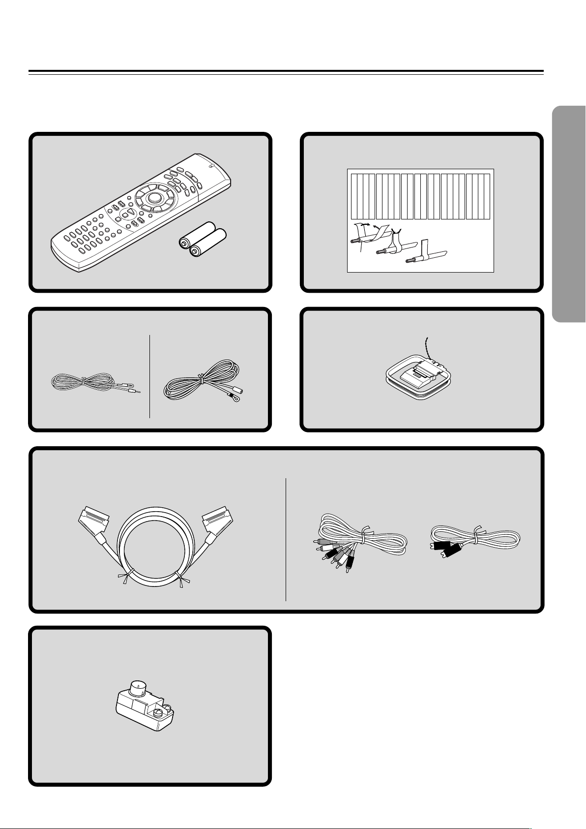
Supplied Accessories
Make sure your box contains everything listed below.
If any pieces are missing, contact your nearest Onkyo service station.
The number of accessories is indicated in brackets.
S video connection
cable [1]
FM antenna (aerial) [1]
AM loop antenna (aerial) [1]
Batteries (size AA/R6/UM3) [2]
Remote controller (RC-484M) [1]
(Other models)
Audio/video
connection cable [1]
Speaker Label [1]
(North American and South
American models)
(Other models)
(European models)
SCART cable [1]
FM outdoor antenna (aerial) adapter [1]*
* Not supplied for USA and European models
Front
Left
Front
Left
SP-B
/
Zone 2
Left
SP-B
/
Zone 2
Left
Surround
Right
Surround
Right
Surround Back
Right
Surround Back
Right
Zone 2
Right
Zone 2
Right
Front
Left
Front
Left
SP-B
/
Zone 2
Left
SP-B
/
Zone 2
Left
Front
Right
Front
Right
SP-B
/
Zone 2
Right
SP-B
/
Zone 2
Right
Front
Right
Front
Right
SP-B
/
Zone 2
Right
SP-B
/
Zone 2
Right
Surround
Right
Surround
Right
Center
Center
Center
Center
Surround
Left
Surround
Left
Surround
Left
Surround
Left
Surround Back
Right
Surround Back
Right
Zone 2
Right
Zone 2
Right
Surround Back
Left
Surround Back
Left
Zone 2
Left
Zone 2
Left
Surround Back
Left
Surround Back
Left
Zone 2
Left
Zone 2
Left
1
2
3
Speaker Cable
8
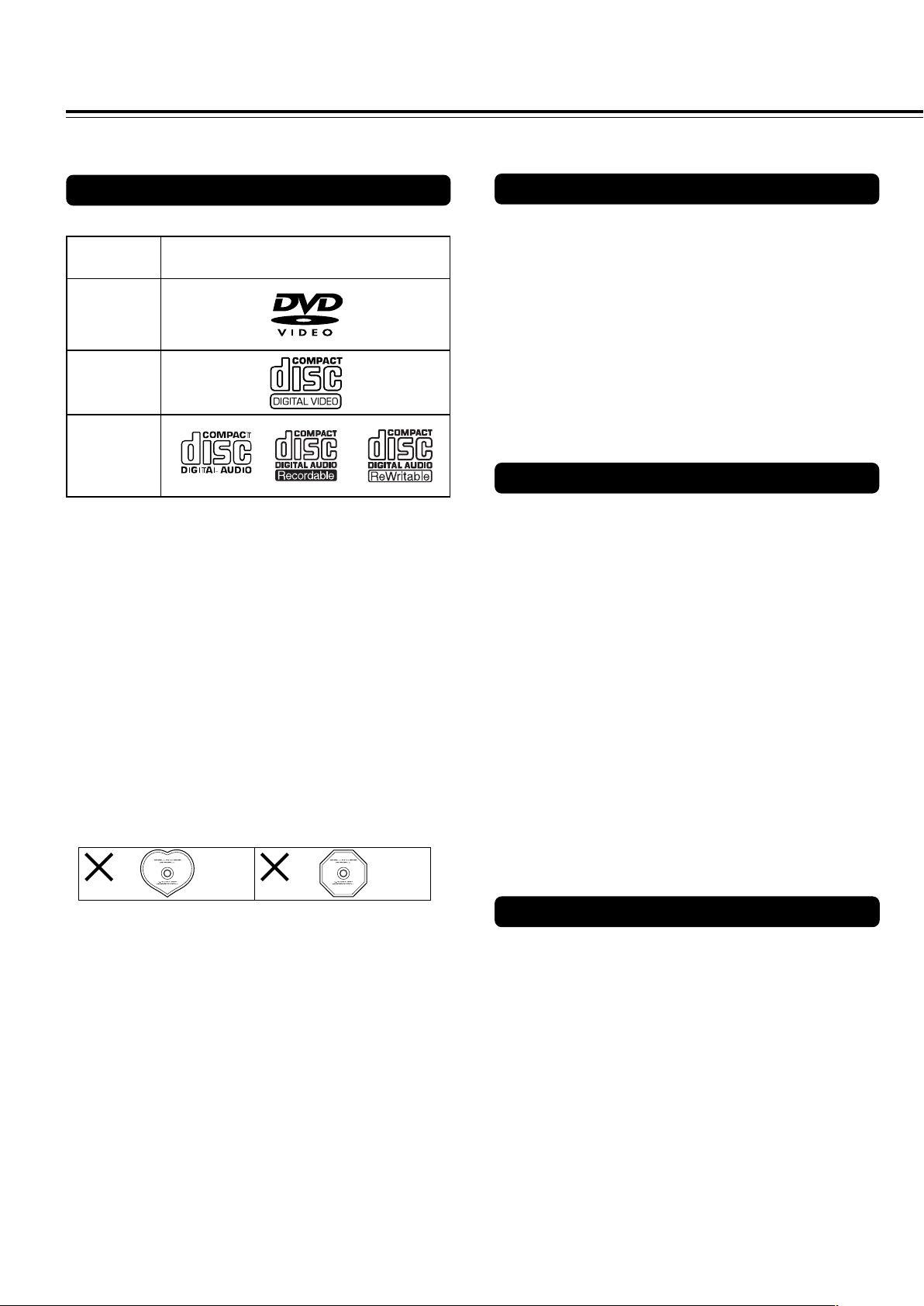
This section shows you how to handle, clean, and store discs.
Notes on Discs
Disc mark
DVD videos
Playable Discs
This DVD Receiver can playback the following discs.
• You cannot playback discs other than those listed above.
• You cannot play discs such as CD-ROM, DVD-RAM, DVD-
RW, DVD-Audio, Photo CD, CD-G etc., even if the marks in
the above table are labeled on those discs.
• This DVD Receiver uses the PAL/NTSC color system, and
cannot playback DVD videos recorded in any other color
system (SECAM, etc.).
• Avoid using heart-shaped or octagonal discs. Playing
irregularly shaped discs may damage the internal
mechanism of the DVD Receiver.
• Do not use discs that have residue from adhesive tape,
rental discs that have peeling labels, or discs that have
custom labels or stickers. Otherwise, you may not be able
to eject the discs or the DVD Receiver may become
inoperative.
About VIDEO CDs
This DVD Receiver supports VIDEO CDs equipped with the
PBC (Version 2.0) function. (PBC is the abbreviation of
Playback Control.)
You can enjoy two playback variations depending on the type
of disc.
• VIDEO CD not equipped with PBC function (Version 1.1)
Sound and movies can be played on this DVD Receiver in
the same way as an audio CD.
• VIDEO CD equipped with PBC function (Version 2.0)
In addition to operation of the VIDEO CD not equipped with
the PBC function, you can enjoy playback with interactive
software and search function using the menu displayed on
the TV screen (Menu Playback). Some of the functions
described in this Instruction Manual may not work with some
discs.
VIDEO CDs
Audio CDs
*1 *1
*
1
This unit can play CD-R and CD-RW discs recorded in CD
Audio or Video CD format, or with MP3 audio files.
However, there may be some discs that cannot be played
back with this unit. The causes of this impossibility include
incompletion of disc finalization and the recording
characteristics of the recorder as well as the properties,
damage or stain of the disc in use and stain or
condensation on the pickup lens of this unit. For details,
please refer to the instruction manual of the recorder.
MP3 compatibility information
• The CD-ROM must be ISO9660 compatible.
• Files should be MPEG1 Audio Layer 3 format, 44.1 or
48kHz, fixed bit-rate. Incompatible files will not play and
“UNPLAYABLE” will be displayed.
• This DVD Receiver is not compatible with variable bit-rate
(VBR) files. Be sure to make MP3 CD with fixed bit-rate
setting.
• This system only plays tracks that are named with the file
extension “.mp3” or “.MP3”.
• This system is not compatible with multi-session discs. If
you try an play a multi-session disc, only the first session
will be played.
• Use CD-R or CD-RW media for recording your MP3 files.
The disc must be finalized in order to play.
• Audio encoded at 128kbps should sound close to regular
audio CD quality. Although this system will play lower bit-
rate MP3 tracks, the sound quality becomes noticeably
worse at lower bit-rates.
• Only the first 8 characters of folder and track names
(excluding the “.mp3” extension) are displayed.
• This system can recognize a maximum of 250 folders and
250 tracks. Discs containing more than 250 folders or tracks
will not play.
Notes on Copyright
It is forbidden by law to copy, broadcast, show, broadcast on
cable, play in public, and rent copyrighted material without
permission.
DVD videos are copy protected, and any recordings made from
these discs will be distorted.
This product incorporates copyright protection technology that is
protected by method claims of certain U.S. patents and other
intellectual property rights owned by Macrovision Corporation
and other rights owners. Use of this copyright protection
technology must be authorized by Macrovision Corporation, and
is intended for home and other limited viewing uses only unless
otherwise authorized by Macrovision Corporation. Reverse
engineering or disassembly is prohibited.
9
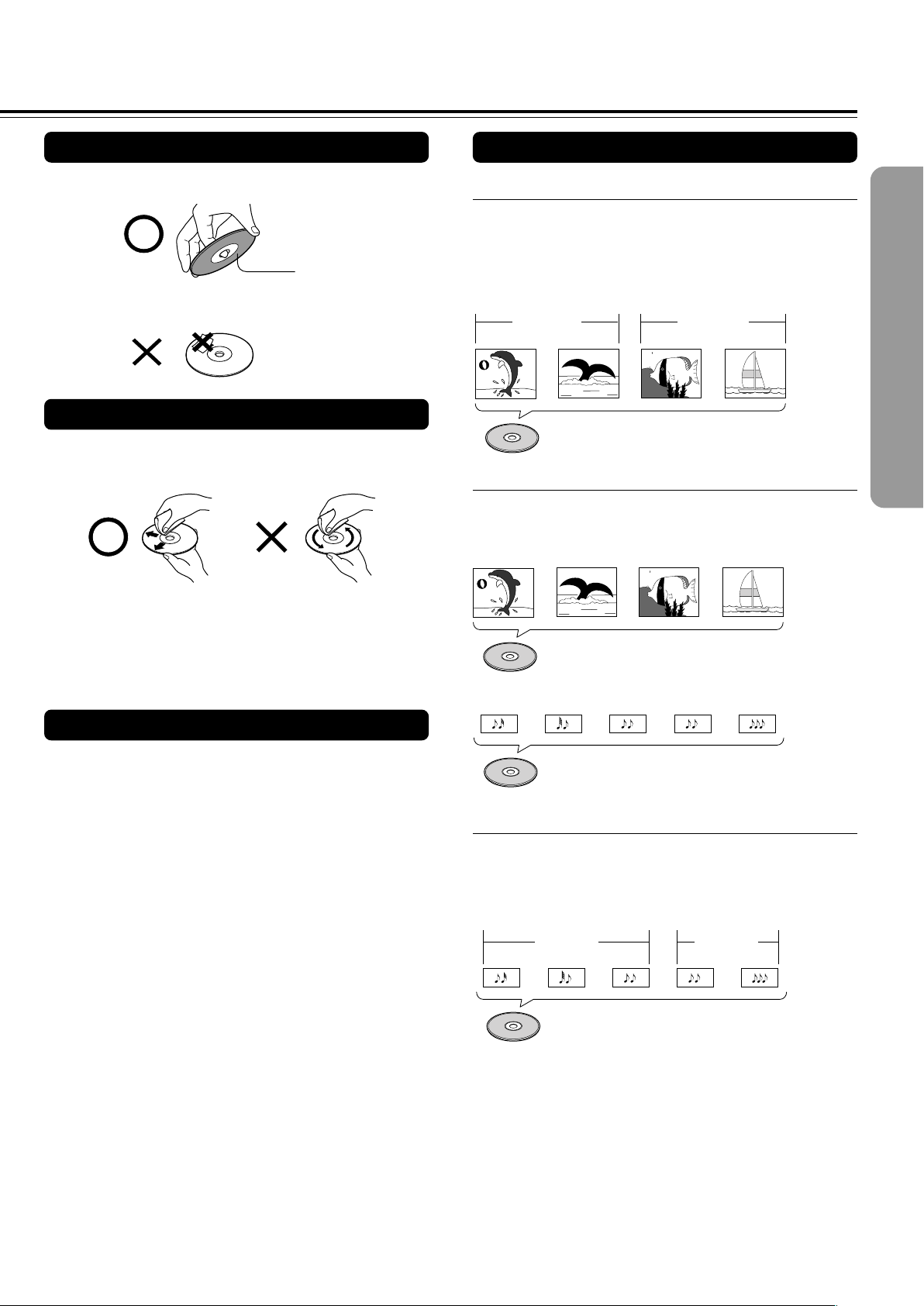
Playback side
Cleaning Discs
• Fingerprints and dust on the disc cause picture and sound
deterioration. Wipe the disc from the center outwards with a
soft cloth. Always keep the disc clean.
• If you cannot wipe off the dust with a soft cloth, wipe the disc
lightly with a slightly moistened soft cloth and finish with a
dry cloth.
• Do not use any type of solvent such as thinner, benzine,
commercially available cleaners or antistatic spray for vinyl
LPs. It may damage the disc.
Storing Discs
• Do not store discs in a place subject to direct sunlight or
near heat sources.
• Do not store discs in places subject to moisture and dust
such as a bathroom or near a humidifier.
• Store discs vertically in a case. Stacking or placing objects
on discs outside of their case may cause warping.
Handling Discs
• Do not touch the playback side of the disc.
• Do not attach paper or tape to discs.
Differences in Disc Composition
■ DVD
All discs are divided up into smaller, more manageable
sections so that you can find specific content more easily.
DVDs are divided into one or more titles. Each title may be
further divided into several chapters. Occassionally, a chapter
may contain index points, effectively dividing the chapter up
into several parts, too.
■ Video CD/CD
Video CDs and CDs are divided into a number of tracks. In
rare cases, a track may contain a number of index points,
effectively dividing the track up into several parts.
■ MP3
MP3 (MPEG1 Audio Layer 3) is a compressed audio file
format. Files are recognized by their file extension “.mp3” or
“.MP3”. Folders that contain MP3 files are automatically
numbered F_001, F_002, etc. Tracks within folders are
automatically numbered T_001, T_002, etc.
Track 2
Track 3
Track 1
Track 2Track 1
Folder 1 Folder 2
MP3
Title 1
Title 2
Chapter 1 Chapter 2
Chapter 2
DVD
Chapter 1
Video CD
Track 1 Track 2 Track 3 Track 4
CD
Track 2 Track 4Track 3Track 1 Track 5
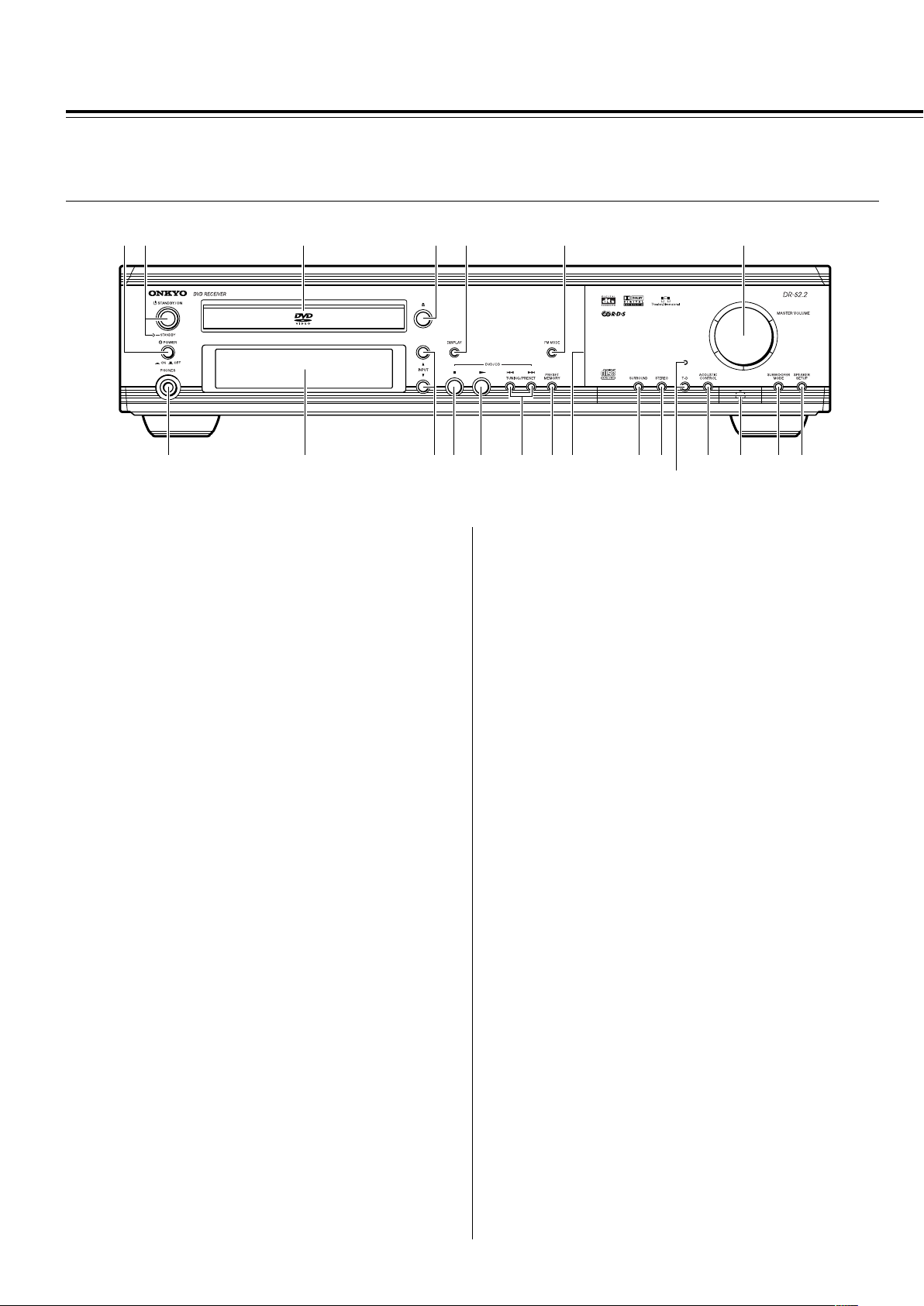
10
Index to Parts and Controls
For operational instructions, refer to the page indicated in brackets.
■Front panel
1 (European and some Asian models only)
POWER switch [26]
Turns on the main power supply for the DVD Receiver. The DVD
Receiver enters standby state. Pressing the switch again to the off
position (— OFF) shuts down the main power supply into the DVD
Receiver.
Before turning on the power, make sure all cables are properly
connected.
2 STANDBY/ON button, STANDBY indicator [26, 37]
When STANDBY/ON button is pressed to ON (while the POWER
switch is set to ON on the European and some Asian models), the
DVD Receiver turns on. The STANDBY indicator turns off and the
display lights up. Pressing the button again returns the DVD
Receiver to the standby state. This state turns off the display,
disables control functions.
3 Disc tray [34]
When loading a disc, place discs in the disc tray with the label side
facing up.
4 0 button [34, 37]
Press to open and close the disc tray.
5 DISPLAY button [62, 63]
Press to change the information being displayed.
6 FM MODE button [38]
Press to switch the reception mode between stereo and monaural.
7 MASTER VOLUME control [42]
The MASTER VOLUME dial is used to control the volume level.
8 PHONES jack [42]
This is a standard stereo jack for connecting stereo headphones.
9 Display [11]
0 INPUT 5/∞ buttons [38, 39, 40]
Press to select the input source.
- 7 button [37]
Press to stop playback. Pressing once enables playback to resume
from a point shortly before the location where it was stopped.
Pressing twice causes the disc to return to the beginning of the
disc when playback starts again.
890-=~!#@$
%
^*&(
12 3 4 5 6 7
= £ button [34, 37]
Press to start or resume playback.
~ TUNING/PRESET 4/¢ buttons [36, 38, 39]
Press to go back or advance to previous chapters/tracks. Also, use
these buttons to change the tuner frequency.
! PRESET MEMORY button [38, 39]
Press to assign the radio station that is currently tuned in to a
preset channel or delete a previously preset station.
@ Front panel illumination
# SURROUND button [48]
Press to select a surround mode.
$ STEREO button [48]
Press to change the listening mode to “Stereo”.
% T-D button, indicator [47]
Press to activate Theater-Dimensional mode. T-D indicator
illuminates in Theater-Dimentional mode. T-D indicator goes off
when other mode is selected.
^ ACOUSTIC CONTROL button [50]
Press to change the acoustic mode to boost the super bass/high
frequency sounds.
& Remote control sensor [15]
Point the remote control toward the remote sensor to operate the
DVD Receiver.
* SUBWOOFER MODE button [31]
Press to select the subwoofer mode.
( (North American and South American model)
SPEAKER A/B button [29, 42]
Press to switch the speaker systems in use between A and B.
(Other models)
SPEAKER SETUP button [30]
Press to select the optimum speaker configuration.
11
213456 7 8 9 0-= ~ @!#$
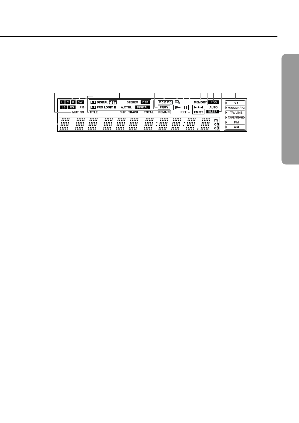
■ Display
1 Multipurpose display
2 MUTING indicator [42]
Flashes when the mute function is active.
3 Speaker setup indicators [29, 30]
Indicate the speaker configuration.
4 SW indicator [31]
Lights up when the subwoofer mode is set to SW Mode 1, 2 or 3.
5 IPM (Intelligent Power Management) indicator [22]
Lights up when the IPM function is active.
6 TITLE, CHP, TRACK, TOTAL, REMAIN indicators [62, 63]
Indicate display mode of the current chapter of DVD or track
number of Video CD or CD.
7 Source/Listening mode indicators [40, 45]
One of source indicators lights to show the format of the current
source. In addition, one of the listening mode indicators lights
according to the current listening mode.
8 PRGV indicator [67]
Lights up when the DVD Receiver is set to progressive-scan video.
9 Inserted disc indicator [34]
Indicates the type of current disc that is loaded.
0 Angle indicator [60]
Lights up while playing a scene recorded with multiple angles.
- £, 8 indicators [34]
Illuminates in play or pause mode.
= RPT. indicator [54]
Illuminates during repeat playback. Also RPT. indicator illuminates
during A-B repeat playback.
~ MEMORY indicator [38]
Lights up when the MEMORY button is pressed in the radio station
preset operation.
! 3¶2, AUTO, FM ST indicators [38]
Indicate the reception mode.
@ RDS indicator (European models only) [39]
Lights up when a RDS station is received.
# SLEEP indicator [43]
Lights up when the sleep timer is active.
$ Input source indicators [38, 40]
Show current input source.
12
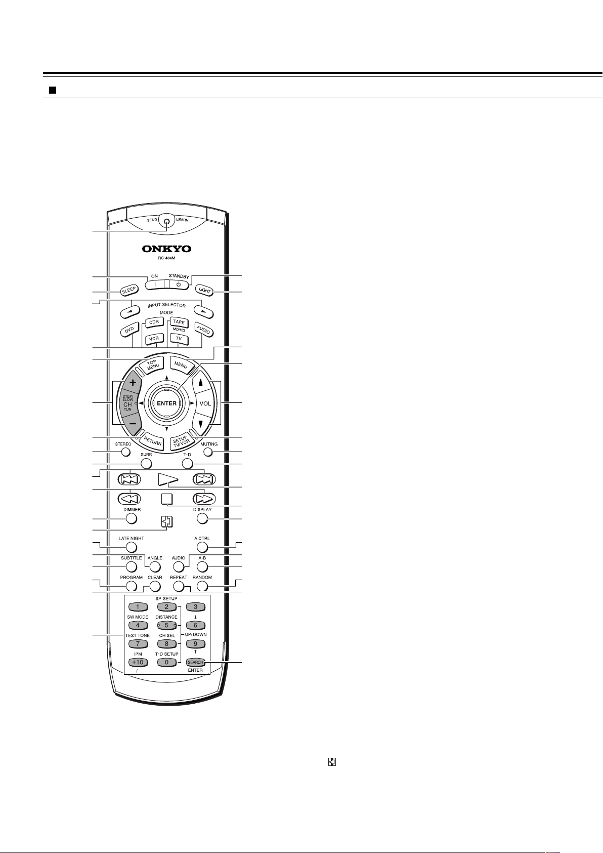
Remote controller
To control the DVD Receiver, press MODE DVD or MODE AUDIO
first. Press MODE DVD to operate DVD section, or MODE AUDIO
to operate receiver section. Functions of graied buttons in the
illustration vary depending on the mode.
1 SEND/LEARN indicator [15, 81, 83]
Lights red when sending a signal.
2 ON button [27]
Turns on the DVD Receiver.
3 SLEEP button [43]
For setting the sleep timer.
4 INPUT SELECTOR 2/3 buttons [39, 40]
Press to select the input source.
5 MODE buttons [15, 41, 78, 80, 82, 83]
For selecting the component to be operated by the remote
controller.
6 TOP MENU button [35, 53]
Press to call up the top menu programmed on the DVD. Depending
on the DVD, the top menu may be identical to the DVD menu.
7 (MODE AUDIO is selected)
CH +/– buttons [39]
For selecting a tuner preset channel.
(MODE DVD is selected)
STEP/SLOW +/– buttons [41]
Press STEP/SLOW +/– during playback to view still frame. Press
and hold STEP/SLOW +/– during playback to view slow playback.
In still frame, press STEP/SLOW + to advance DVDs and Video
CDs frame by frame and STEP/SLOW – to back up a few frames at
a time (DVD only).
8 RETURN button [35, 64]
Use to go one menu back (current settings are maintained). Use
RETURN when you do not want to change the option setting in a
menu.
9 STEREO button [48]
Press to change the listening mode to “Stereo”.
0 SURR button [48]
Press to select the surround mode.
- 4/¢ buttons [35, 36]
During playback of DVD, CD and Video CD, press 4 to go back
to a previous chapter/track and ¢ to advance to the next chapter/
track .
= 1/¡ buttons [36]
During playback of DVD and Video CD, press ¡ to perform fast
forward scanning or 1 to perform fast reverse scanning of DVD
and Video CD. When a CD or MP3 is loaded, audio scanning is
performed.
~ DIMMER button [43]
For adjusting the brightness of the front display.
! button [34, 51]
Press to pause playback of a disc. Press again to resume
playback.
*
(
)
_
+
¡
™
£
¢
∞
§
≠
•
¶
ª
–
º
2
1
3
4
5
6
7
8
9
0
-
=
~
!
@
#
$
%
^
&
Index to Parts and Controls
Explanations on this page are for controlling the DVD Receiver.
The supplied remote controller is a useful tool to help you operate of
your home theater.
To operate other components, see “Operating the Onkyo MD
Recorder/CD Recorder/Cassette Tape Deck/Hard Disk Recorder With
the Supplied Remote Controller” on page 41 and “Controlling other
components connected to the DVD Receiver” on pages 78-83.

13
@ LATE NIGHT button [50]
Press to change the late night setting.
# ANGLE button [60]
Some DVDs are recorded with various camera angle playback
options. Press ANGLE repeatedly to display different camera
angles.
$ SUBTITLE button [61]
Press repeatedly to select one of the subtitle languages
programmed on a DVD or to turn the subtitles off.
% PROGRAM button [53, 56, 57, 58]
You can program titles, chapters, or tracks to play back in a desired
order. Programs can be a maximum of 24 steps.
^ CLEAR button [53, 54, 57]
Works in conjunction with a number of player functions. Use to
cancel repeat and random playback, and to edit programs.
& (When MODE DVD is selected)
Number buttons (1-9, +10, 0) [35, 52, 78]
Use to perform direct title/folder and chapter/track searches, and to
input numerical values.
SEARCH button [52]
Press to perform a title/folder, chapter/track or elapsed time search.
(When MODE AUDIO is selected)
SW MODE button [31]
Press to select the subwoofer mode.
TEST TONE button [33, 49]
Outputs a test tone for setting speaker levels.
IPM (Intelligent Power Management) button [22]
Activates the IPM function.
SP SETUP button [29, 30]
Press to select the optimum speaker configuration.
DISTANCE button [32]
For setting the distances for each speaker.
CH SEL button [33, 49]
Selects a speaker for changing the speaker output level.
T-D SETUP [47]
For setting the T-D parameters.
UP/DOWN 5/∞ [32, 33, 47, 49]
Press to adjust the value.
* STANDBY button [37]
Put the DVD Receiver in standby.
( LIGHT button
Illuminates the buttons. This button is useful when using the
remote controller in dark locations. When pressed, the buttons on
the remote controller light green.
) MENU button [35, 53]
Use to display or close the DVD menu or MP3 Navigator screen.
_ Cursor (2/3/5/∞/ENTER) [27, 34, 53, 64]
Use to move through the options on menu screens. Press to enter
settings.
+ VOL 5/∞ buttons [42]
For adjusting the volume.
¡ SETUP button [27, 64]
Press when the DVD Receiver is in either play or stop mode to
open and close the Setup screen.
™ MUTING button [42]
Activates the mute function.
£ T-D button [47]
Press to activate Theater-Dimensional mode.
¢ £ button [34, 37, 52]
Press to start or resume playback.
∞ 7 button [35, 37]
Press to stop playback. Pressing once enables playback to resume
from a point shortly before the location where it was stopped.
Pressing twice causes the disc to return to the beginning of the
disc when playback starts again.
§ DISPLAY button [62, 63]
Press to change the information being displayed.
¶ A.CTRL button [50]
Press to change the acoustic mode to boost the super bass/high
frequency sounds.
• AUDIO button [61]
Press repeatedly to select one of the audio languages programmed
on a DVD.
For Video CD, CD and MP3, each press changes the audio output
as follows.
→ Stereo → 1/L(Left) → 2/R(Right)
ª A-B button [54]
Press at the beginning and end of the section you want to repeat or
to mark a location you want to return to.
º RANDOM button [55]
Press to play chapters/tracks in random order.
– REPEAT button [54]
Use to set the repeat mode.
≠ ENTER button [81-83]
Press to program the commands of remote controller for other
devices into the remote controller.
14
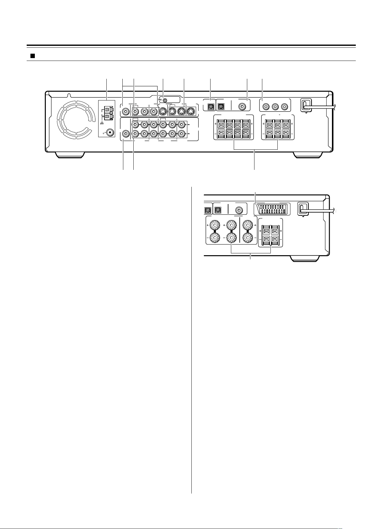
Shapes of jacks vary depending on the area which it was purchased.
1 ANTENNA terminals [24, 25]
These terminals are for connecting the FM antenna and AM
antenna.
2 MON OUT jacks [16, 17]
The monitor output includes both RCA type and S video
configurations. This output is for connecting television monitor or
projector.
3 VIDEO (VIDEO 1 IN / VIDEO 2 IN/OUT) jacks [21]
There are 2 video inputs and 1 outputs. Connect LD players, VCRs
or other video components to the video inputs. The video output
channel can be used to connect video tape recorder for making
recordings.
4 z REMOTE CONTROL connector [23]
Connect the Onkyo components that have z connectors such as
a CD player, and cassette tape deck using the z cables provided
with them. When these components are interconnected, they can
be controlled from the remote controller provided with the DVD
Receiver.
After connecting the z connectors, check the operation of the
remote controller buttons for use in controlling other components.
5 S VIDEO (VIDEO 1 IN / VIDEO 2 IN/OUT) jacks [21]
There are 2 video inputs and 1 output. Connect LD players, VCRs
or other video components to the video inputs. The video output
channel can be used to be connected to video tape recorder for
making recordings.
6 DIGITAL OUTPUT OPT jack [21, 22]
This jack is for connecting MD recorder, CD recorder, hard disk
recorder or other component with optical fiber cable.
7 DIGITAL INPUT (VIDEO 1 COAX, VIDEO 2 OPT) jacks [21]
These are the digital audio inputs. There are 1 digital input with
optical jacks and 1 with a coaxial jack. The inputs accept digital
audio signals from MD players, hard disk recorders, CD players, or
other digital source component.
8 (European models)
AV CONNECTOR terminal [17]
Use a 21-pin SCART cable to connect to a TV or monitor
compatible with this type of connection. Both audio (2 channel
stereo) and video (Video, S-video, and RGB) signals are output
from the AV CONNECTOR.
(Other models)
COMPONENT VIDEO OUTPUT Y/P
B/PR jacks [16]
If your TV or monitor has component video inputs, you can produce
a higher quality picture on your TV or monitor by connecting to the
component video outputs on this unit.
9 SUB WOOFER PRE OUT jack [18, 19]
This terminal is for connecting an active subwoofer.
0 AUDIO L/R (TV/LINE IN / TAPE/MD/HD IN/OUT /
VIDEO 1 IN / VIDEO 2/CDR/PC IN/OUT) jacks [16, 17]
These are the analog audio inputs and outputs. There are 4 audio
inputs and 2 audio outputs. The audio inputs and outputs require
RCA type connectors.
When connecting a VCR or other video component, make sure you
connect the audio and video leads together (i.e., both to VIDEO 1).
- (North American and South American model)
FRONT SPEAKERS A/B, SURROUND SPEAKERS and
CENTER SPEAKER terminals [18]
FRONT SPEAKERS A system: To enjoy surround sound. Speaker
terminals are provided for the front left, front right, center, surround
left and surround right speakers.
FRONT SPEAKERS B system: To enjoy stereo sound. Speaker
terminals are provided for the front left and front right.
(Other models)
FRONT SPEAKERS, CENTER SPEAKER and SURROUND
SPEAKERS terminals [19]
Speaker terminals are provided for the front left, front right, center,
surround left and surround right speakers. Speaker outputs are
compatible with banana plug connectors.
Index to Parts and Controls
SURROUND
SPEAKERS
R
L
FRONT SPEAKERS CENTER
SPEAKER
R
L
DIGITAL INPUT
VIDEO 2 VIDEO 1
OPT
COAX
AV
CONNECTOR
8
-
Rear panel
REMOTE
CONTROL
OUT
2 ––VIDEO–– 1 VIDEO 2 VIDEO 1
IN
IN IN
IN
OUT
OUT
IN OUT IN
IN
IN
VIDEO2
CDR/PC
VIDEO 1 TAPE
MD/HD
TV/LINE
MON
OUT
MON
OUT
L
R
VIDEO
S VIDEO
AUDIO
SUB
WOOFER
PRE OUT
AUDIO
FM
75
ANTENNA
DIGITAL
OUTPUT
DIGITAL INPUT
VIDEO 2 VIDEO 1
OPT
OPT
COAX
AM
Y
P
B
P
R
COMPONENT VIDEO OUTPUT
CENTER
SPEAKER
SURROUND
SPEAKERS
R
L
R
L
R
BA
L
FRONT SPEAKERS
12 4 5 6 783
90 -
North American and South
American model
European model
15
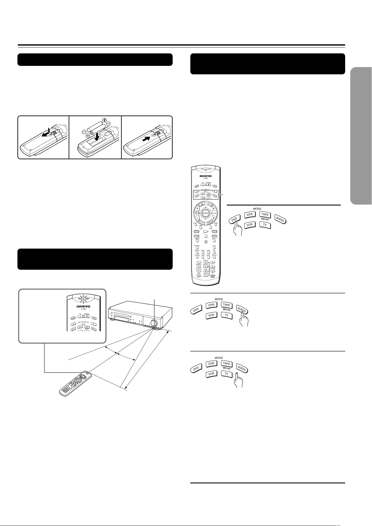
Preparing the Remote Controller
Inserting the Batteries
1 Detach the battery cover.
2 Insert the two size AA/R6/UM3 batteries.
Be sure to match the + and – ends of the batteries with
the diagram inside the battery compartment.
3 Attach the battery cover.
Switching the remote controller
function modes
Some buttons on the remote controller have two or
more functions. To set the functionality of these
buttons, press one of the six MODE (DVD, CDR, TAPE/
MD/HD, AUDIO, VCR, TV) buttons in advance.
The function mode remains the same until another
MODE button is pressed.
(Details about the functions and the related function
modes are explained in each section.)
Notes
• Do not mix new batteries with old batteries or different kinds of
batteries.
• To avoid corrosion, remove the batteries if the remote controller
is not to be used for a long time.
• Remove dead batteries immediately to avoid damage from
corrosion. If the remote controller does not operate smoothly,
replace both batteries at the same time.
• The life of the supplied batteries is about six months but this
varies depending on usage.
Pointing the remote controller in the
right direction
Point the remote controller toward the remote control
sensor.
Notes
• Place the unit away from strong light such as direct sunlight or
inverted fluorescent light which can prevent proper operation of
the remote controller.
• Using another remote controller of the same type in the same
room or using the unit near equipment which uses infrared rays
may cause operational interference.
• Do not put any object (such as a book) on the remote controller.
The buttons of the remote controller may be pressed by mistake
and drain the batteries.
• Make sure the audio rack doors do not have colored glass.
Placing the unit behind such doors may prevent proper remote
controller operation.
• If there is any obstacle between the remote controller and the
remote control sensor, the remote controller will not operate.
Press MODE AUDIO first before operating the speaker
setting and sound related operations.
Press MODE CDR first before operating the
z-connected Onkyo CD recorder (see pages 21, 23
and 41)
Press MODE TAPE/MD/HD first before operating the
z-connected Onkyo MD recorder, cassette tape deck
or hard disk recorder (see pages 21, 23 and 41).
Press MODE VCR or MODE TV first before operating
your VCR or TV.
To operate the TV with the supplied remote controller,
you need to let the remote controller learn the TV
remote control signals (see pages 78 and 79).
12
3
The SEND/
LEARN indicator
is lit while any
button on the
remote controller
is pressed.
30˚
30˚
About 5 m (16 feet)
Remote control sensor
MODE buttons
Press MODE DVD first before operating
the built-in DVD player.
16
Connecting to a TV (Other than European model)
Before connecting
• Refer also to the instruction manual of the TV.
• When you connect the DVD Receiver to the TV, be sure to turn
off the power and unplug both the units from the mains before
making any connections.
• Connect the DVD Receiver to the TV directly. If you connect the
DVD Receiver to a VCR, TV/VCR combination, or video selector,
the playback picture may be distorted as DVD videos are copy
protected.
L (White)
R (Red)
• Connect the plugs securely.
• Note that one audio/video connection
cable and one S video connection cable
are supplied.
Incomplete
Insert completely
Video
(Yellow)
REMOTE
CONTROL
OUT
2 ––VIDEO–– 1 VIDEO 2 VIDEO 1
IN
IN IN
IN
OUT
OUT
IN OUT IN
IN
IN
VIDEO2
CDR/PC
VIDEO 1 TAPE
MD/HD
TV/LINE
MON
OUT
MON
OUT
L
R
VIDEO
S VIDEO
AUDIO
SUB
WOOFER
PRE OUT
SURROUND
SPEAKERS
AUDIO
R
L
FRONT SPEAKERS CENTER
SPEAKER
R
L
FM
75
ANTENNA
DIGITAL
OUTPUT
DIGITAL INPUT
VIDEO 2 VIDEO 1
OPT
OPT
COAX
AM
Y
P
B
P
R
COMPONENT VIDEO OUTPUT
S VIDEO
IN
VIDEO
IN
AUDIO
OUT
RL YP
B
P
R
COMPONENT
VIDEO IN
■ Connecting to a TV (or projector)
Using the supplied audio/video connection cable, make
audio connections from the TV/LINE IN L and R jacks to
the corresponding audio output jacks on the TV. In the
same manner, make video connections from the VIDEO
MON OUT jack to the corresponding video input jack on
the TV.
If your TV has a S video input jack and/or component video
input jacks, make S video connection to the S VIDEO MON
OUT jack using supplied S video connection cable and/or
make component video connection to the COMPONENT
VIDEO OUTPUT jacks using component video connection
cable (not supplied). These connections allow you to enjoy
higher quality picture playback. Be sure not to disconnect
VIDEO MON OUT.
Y
P
B
PR
DO NOT connect the
power cord (mains lead)
at this time.
S video connection cable
TV or projector
Audio/video connection cable
Be sure to set the digital output setting after
connection using the Setup Navigator explained in
“Setting Up the DVD Receiver” starting on page 27
or the function setting menu explained in
“Customizing the Function Settings” starting on
page 64.
Component video
connection cable
Signal flow
Notes
• Actual labels for component video inputs may vary depending
on the TV manufacturer (ex. Y/CB/CR, Y/B-Y/R-Y, etc.).
• In some TVs, the color levels of the playback picture may be
reduced slightly or the tint may change. In such a case, adjust
the TV for optimum performance.
Note
The signal that comes in from
S VIDEO IN is sent to S
VIDEO OUT. The signal that
comes in from VIDEO IN is
sent to VIDEO OUT.
See “Turning the unit on/off with the TV’s power
switch — IPM function” on page 22 for Inteligent
Power Management (IPM) function.
17
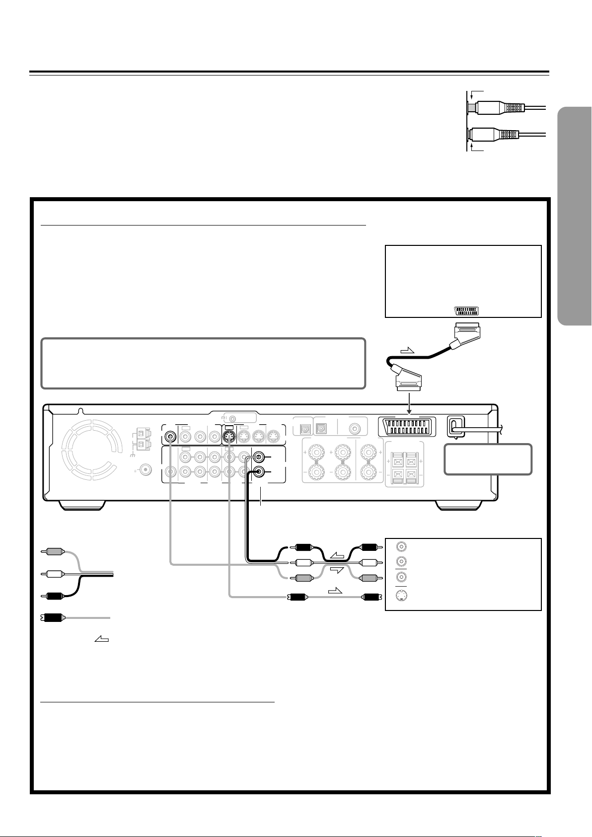
Connecting to a TV (European model)
Before connecting
• Refer also to the instruction manual of the TV.
• When you connect the DVD Receiver to the TV, be sure to turn
off the power and unplug both the units from the mains before
making any connections.
• Connect the DVD Receiver to the TV directly. If you connect the
DVD Receiver to a VCR, TV/VCR combination, or video selector,
the playback picture may be distorted as DVD videos are copy
protected.
• Connect the plugs securely.
Incomplete
Insert completely
REMOTE
CONTROL
OUT
2 ––VIDEO–– 1 VIDEO 2 VIDEO 1
IN
IN IN
IN
OUT
OUT
IN OUT IN
IN
IN
VIDEO2
CDR/PC
VIDEO 1 TAPE
MD/HD
TV/LINE
MON
OUT
MON
OUT
L
R
VIDEO
S VIDEO
AUDIO
SUB
WOOFER
PRE OUT
SURROUND
SPEAKERS
AUDIO
R
L
FRONT SPEAKERS CENTER
SPEAKER
R
L
FM
75
ANTENNA
DIGITAL
OUTPUT
DIGITAL INPUT
VIDEO 2 VIDEO 1
OPT
OPT
COAX
AM
AV
CONNECTOR
S VIDEO
IN
VIDEO
IN
AUDIO
OUT
R
L
AC
CONNECTOR
■ Connecting to a TV Using the SCART Cable
Connect the DVD Receiver and your TV using the supplied SCART cable.
If the TV is compatible with S video signals
After completing the steps on page 26, set “Video Out” to “S Video” using the menu
explained in “Customizing the Function Settings” starting from page 64. See page 67 for
direct information.
If an RGB monitor is connected to the DVD Receiver
After completing the steps on page 26, set “Video Out” to “RGB” using the menu explained
in “Customizing the Function Settings” starting from page 64. See page 67 for direct
information.
■ Connecting to a TV usinf the Audio/Video
connection cable or S video connection
cable
If the TV or monitor does not has an AV CONNECTOR
input terminal, make video connection using audio/video
connection cable.
If your TV has an S video input jack, make the S video
connection. The S video connection will provide higher
quality picture playback. Be sure not to disconnect VIDEO
MON OUT.
DO NOT connect the
power cord (mains lead)
at this time.
TV or projector
SCART cable
To AC CONNECTOR
input terminal
TV or projector
Be sure to set the digital output setting after connection using the
Setup Navigator explained in “Setting Up the DVD Receiver” starting
on page 27 or the function setting menu explained in “Customizing
the Function Settings” starting on page 64.
L (White)
R (Red)
Video
(Yellow)
S video connection cable
Audio/video
connection cable
Signal flow
See “Turning the unit on/off with the TV’s power
switch — IPM function” on page 22 for Inteligent
Power Management (IPM) function.
18
REMOTE
CONTROL
OUT
2 ––VIDEO–– 1 VIDEO 2 VIDEO 1
IN
IN IN
IN
OUT
OUT
IN OUT IN
IN
IN
VIDEO2
CDR/PC
VIDEO 1 TAPE
MD/HD
TV/LINE
MON
OUT
MON
OUT
L
R
VIDEO
S VIDEO
AUDIO
SUB
WOOFER
PRE OUT
AUDIO
FM
75
ANTENNA
DIGITAL
OUTPUT
DIGITAL INPUT
VIDEO 2 VIDEO 1
OPT
OPT
COAX
AM
Y
P
B
P
R
COMPONENT VIDEO OUTPUT
CENTER
SPEAKER
SURROUND
SPEAKERS
R
L
R
L
R
BA
L
FRONT SPEAKERS
CENTER
SPEAKER
SURROUND
SPEAKERS
R
L
R
L
B
FRONT SPEAKERS
R
A
L
FRONT SPEAKERS
R
A
L
R
L
B
CENTER
SPEAKER
SURROUND
SPEAKERS
R
L
+–+–
+–+–
+–
+– +–
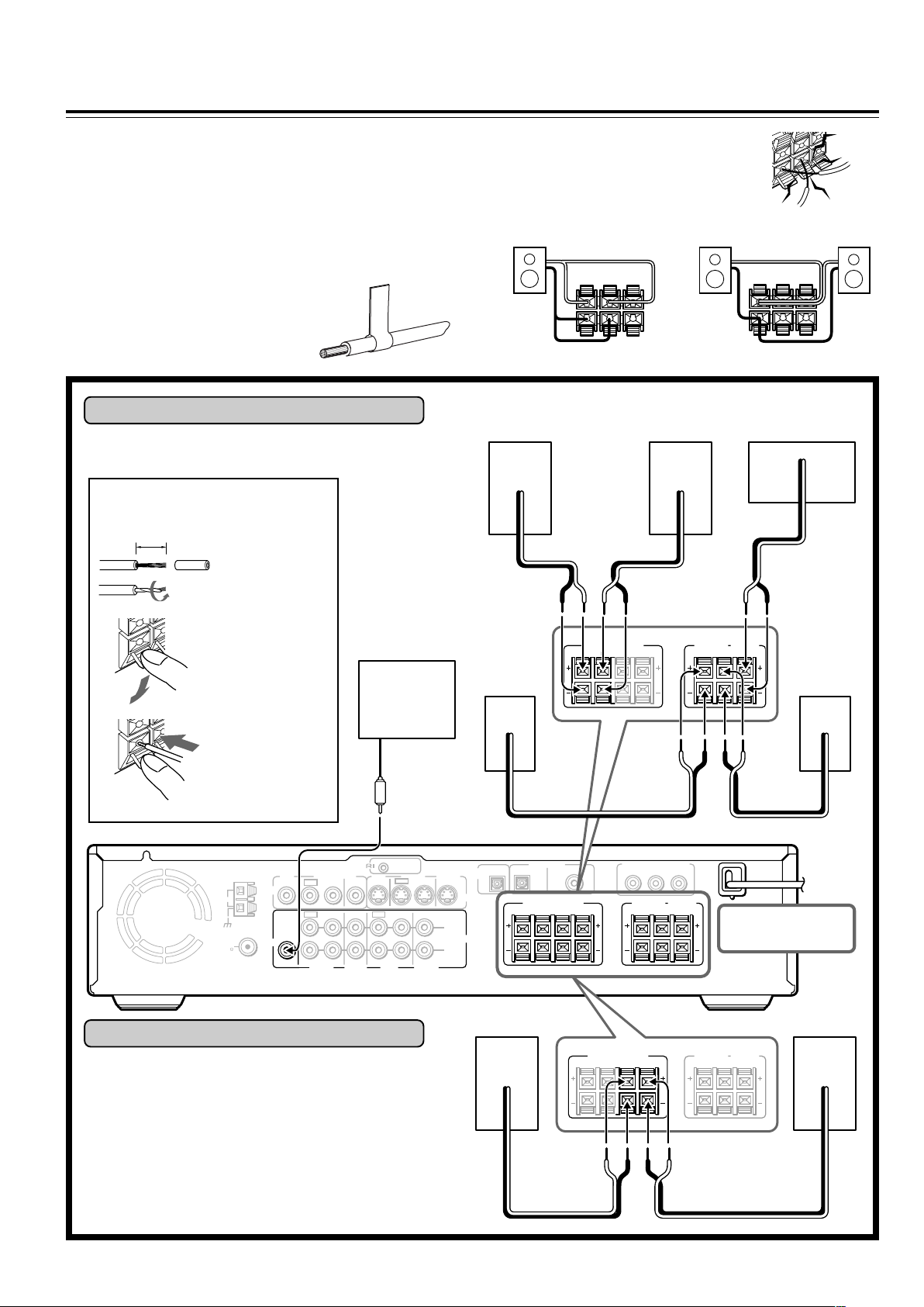
Connecting Speakers (North American and South American model)
Before connecting
• Refer also to the instruction manuals of the speakers.
• This DVD Receiver is designed to reproduce optimum sound
quality when speakers with the impedances specified below are
connected. Please check the following information and choose
speakers with appropriate impedances for the connections.
Front speakers: 6 ohms min. per speaker
Center speaker: 6 ohms min.
Surround Speakers : 6 ohms min. per speaker
• Attach supplied speaker labels to
speaker cables to connect speakers
correctly.
• To prevent damage to circuits, never short-
circuit the positive (+) and negative (–)
speaker wires.
• Do not connect the speaker cable to the L
and R connectors at the same time and do
not connect more than one speaker to the
same speaker connectors.
Surround
(R)
10 mm (3/8”)
Active
subwoofer
Surround
(L)
Connecting to SPEAKERS A
The main speaker system is SPEAKERS A.
Follow the illustration on the right.
How to connect to the speaker
connectors
Press and hold
the lever.
Insert the stripped
end of the cord.
By releasing the
lever, the lever is
replaced.
Front (R)
Front (L)
Connecting to SPEAKERS B
To place the additional speaker system (for the second
room), make the SPEAKERS B connection on the right.
NO!
DO NOT connect the
power cord (mains lead)
at this time.
NO!
NO!
+
–
+
–
LR
+
–
+
–
LR
Front (R) Front (L) Center
Strip 10 mm (3/8”)
from the end of
each cord, then
twist the exposed
wires tightly.
19
REMOTE
CONTROL
OUT
2 ––VIDEO–– 1 VIDEO 2 VIDEO 1
IN
IN IN
IN
OUT
OUT
IN OUT IN
IN
IN
VIDEO2
CDR/PC
VIDEO 1 TAPE
MD/HD
TV/LINE
MON
OUT
MON
OUT
L
R
VIDEO
S VIDEO
AUDIO
SUB
WOOFER
PRE OUT
SURROUND
SPEAKERS
AUDIO
R
L
FRONT SPEAKERS CENTER
SPEAKER
R
L
FM
75
ANTENNA
DIGITAL
OUTPUT
DIGITAL INPUT
VIDEO 2 VIDEO 1
OPT
OPT
COAX
AM
Y
P
B
P
R
COMPONENT VIDEO OUTPUT
+–+–
+–
+– +–
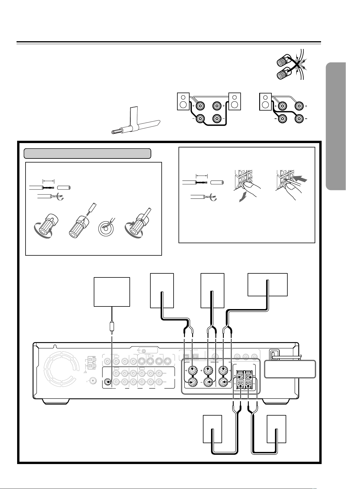
Connecting Speakers (Other models)
Before connecting
• Refer also to the instruction manuals of the speakers.
• This DVD Receiver is designed to reproduce optimum sound
quality when speakers with the impedances specified below are
connected. Please check the following information and choose
speakers with appropriate impedances for the connections.
Front speakers: 6 ohms min. per speaker
Center speaker: 6 ohms min.
Surround Speakers : 6 ohms min. per speaker
• Attach supplied speaker labels to
speaker cables to connect speakers
correctly.
• To prevent damage to circuits, never short-
circuit the positive (+) and negative (–)
speaker wires.
• Do not connect the speaker cable to the L
and R connectors at the same time and do
not connect more than one speaker to the
same speaker connectors.
10 mm
Active
subwoofer
Surround (L)
Connecting to SPEAKERS
How to connect to the SURROUND SPEAKERS
and CENTER SPEAKER terminals
Press and hold
the lever.
Insert the stripped
end of the cord.
By releasing the
lever, the lever is
replaced.
NO!
DO NOT connect the
power cord (mains lead)
at this time.
NO!NO!
R
L
R
L
Strip 10 mm from
the end of each
cable, then twist
the exposed
wires tightly.
Front (R) Front (L) Center
Surround (R)
15 mm
How to connect to the FRONT SPEAKER terminals
Loosen the screw. Fully insert the end
of the cable.
Strip 15 mm from the end of each
cable, then twist the exposed wires
tightly.
Tighten the screw,
20
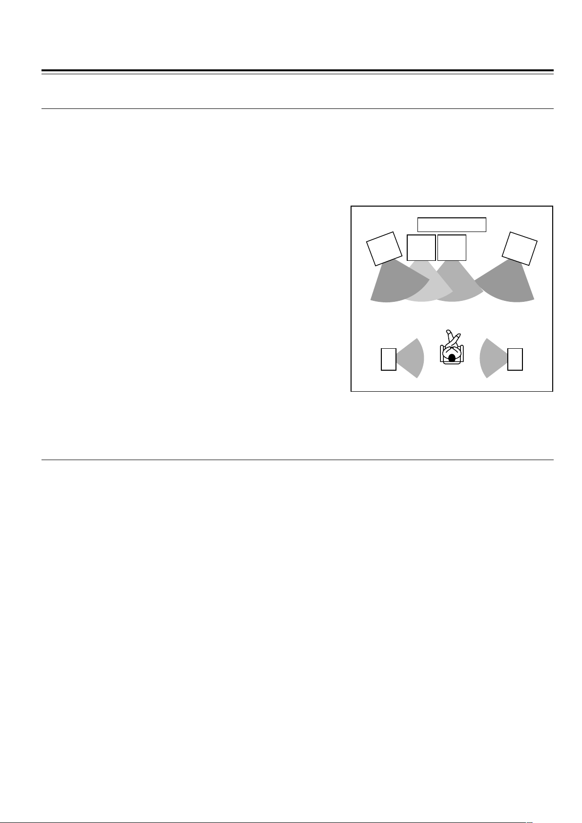
Positioning Speakers
■ Standard speaker placement of the speakers system (standard speaker placement of the
SPEAKERS A system for North American and South American model)
Speaker placement plays an important role in the reproduction of Surround sound. The placement of the speakers varies depending
on the size of the room and the wall coverings used in the room. The illustration below shows an example of a layout for standard
speaker placement. Refer to this example when you position the speakers in order to experience the best of Surround sound.
For ideal Surround effects, all speakers should be installed.
If a center speaker or subwoofer is not connected, the sound from the unused channel is properly distributed to the connected
speakers in order to reproduce the best Surround sound possible.
Front
The center speaker reproduces a richer sound image by enhancing the
perception of the sound's source and movement.
The left, right, and center speakers should face the seated listener and be
placed at ear level.
Surround
The surround speakers reproduce the feel of a moving sound while creating
the sensation of being in the middle of the action.
Place the left and right surround speakers 1 meter (3 feet) above the
listener's ear level and facing toward the sides of the room, making sure that
the listener is within the speakers’ dispersion angle.
Subwoofer
Install a subwoofer with a built-in power amplifier for powerful bass sounds.
The placement of the subwoofer does not affect the final quality of the sound
image much, therefore, you can install it wherever it is convenient.
Refer to the speakers’ instruction manuals for details.
■ For North American and South American models
Two speaker systems (FRONT SPEAKERS A and FRONT SPEAKERS B) can be connected to the DVD Receiver.
For example, you can place the FRONT SPEAKERS A system in the main room, and the FRONT SPEAKERS B system in a
second room.
The configuration of the FRONT SPEAKERS A system
The FRONT SPEAKERS A system consists of the front left, center, and right speakers, surround left and right speakers, and
subwoofer.
You can reproduce the sounds such as Dolby surround and DTS surround.
The configuration of the FRONT SPEAKERS B system
The FRONT SPEAKERS B system consists of the front left and right speakers.
You can reproduce only monaural and stereo sounds.
TV/Screen
Front
Center
Speaker
Front
right
Speaker
Front
left
Speaker
Sub-
woofer
Surround
left
Speaker
Surround
right
Speaker
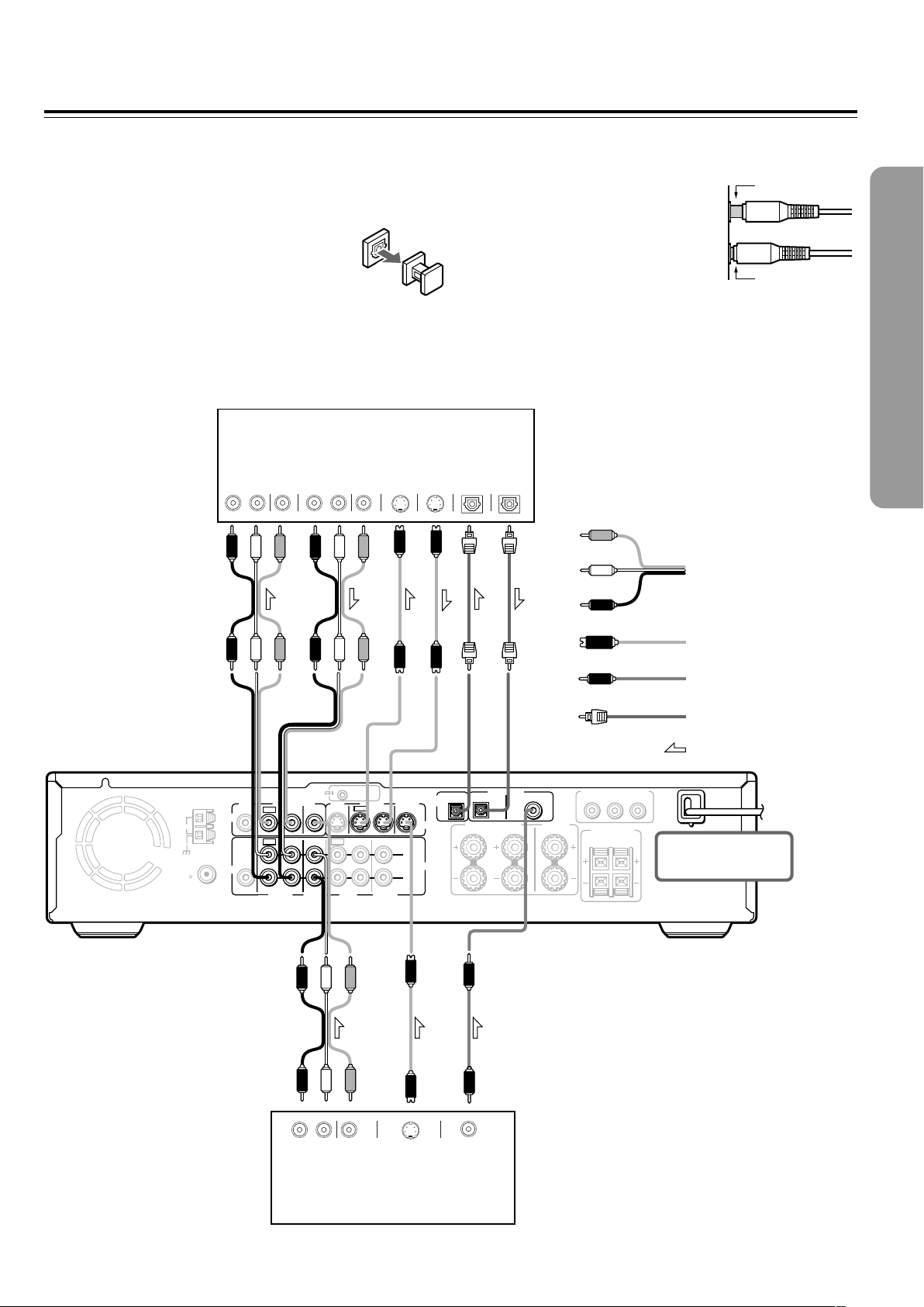
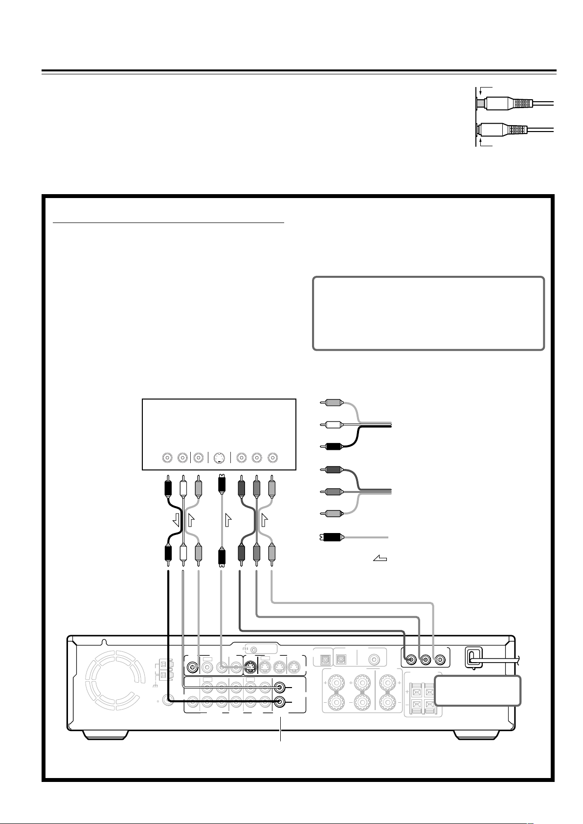
21
Connecting to Audio/Video Equipment
Before connecting
• Refer also to the instruction manual of each component to be
connected.
• When you connect the DVD Receiver to audio/video equipment, be
sure to turn off the power and unplug all the units from the mains before
making any connections.
• About the DIGITAL INPUT (OPT) and DIGITAL
OUTPUT (OPT) connectors
Remove the protective caps before making
connections. When not in use, be sure to replace them.
• About the VIDEO 1 and VIDEO 2 jacks/connectors
The video input/output connections are also necessary even if you
make the S video input/output connections.
• Connect the plugs securely.
• Note that one audio/video connection cable
and one S video connection cable are
supplied (if not used in the connection on
the opposite page).
Incomplete
Insert completely
REMOTE
CONTROL
OUT
2 ––VIDEO–– 1 VIDEO 2 VIDEO 1
IN
IN IN
IN
OUT
OUT
IN OUT IN
IN
IN
VIDEO2
CDR/PC
VIDEO 1 TAPE
MD/HD
TV/LINE
MON
OUT
MON
OUT
L
R
VIDEO
S VIDEO
AUDIO
SUB
WOOFER
PRE OUT
SURROUND
SPEAKERS
AUDIO
R
L
FRONT SPEAKERS CENTER
SPEAKER
R
L
FM
75
ANTENNA
DIGITAL
OUTPUT
DIGITAL INPUT
VIDEO 2 VIDEO 1
OPT
OPT
COAX
AM
Y
PB
PR
COMPONENT VIDEO OUTPUT
S VIDEO
IN
S VIDEO
OUT
VIDEO
IN
AUDIO
IN
RL RL
VIDEO
OUT
AUDIO
OUT
S VIDEO
OUT
RL
VIDEO
OUT
AUDIO
OUT
DIGITAL
OUT
COAXIAL
DIGITAL
IN
OPTICAL
DIGITAL
OUT
OPTICAL
VCR, CD Recorder,
DVD Recorder etc.
Satellite tuner, LD Player, BS
digital tuner, Video Cassette
Player etc.
L (White)
R (Red)
Video
(Yellow)
Audio/video connection
cable
S video connection
cable
Coaxial cable
Optical fiber cable
Signal flow
DO NOT connect the
power cord (mains lead)
at this time.
22
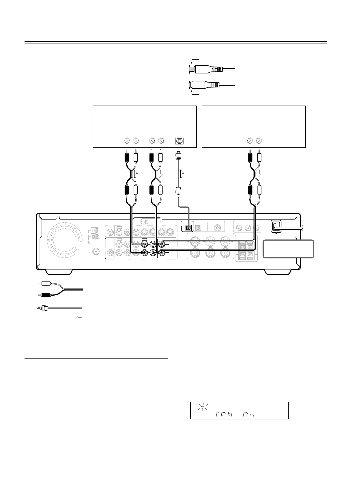
Connecting to Audio/Video Equipment
Before connecting
• Refer also to the instruction manual of each component to be
connected.
• When you connect the DVD Receiver to audio/video equipment, be
sure to turn off the power and unplug all the units from the mains
before making any connections.
Incomplete
Insert completely
REMOTE
CONTROL
OUT
2 ––VIDEO–– 1 VIDEO 2 VIDEO 1
IN
IN IN
IN
OUT
OUT
IN OUT IN
IN
IN
VIDEO2
CDR/PC
VIDEO 1 TAPE
MD/HD
TV/LINE
MON
OUT
MON
OUT
L
R
VIDEO
S VIDEO
AUDIO
SUB
WOOFER
PRE OUT
SURROUND
SPEAKERS
AUDIO
R
L
FRONT SPEAKERS CENTER
SPEAKER
R
L
FM
75
ANTENNA
DIGITAL
OUTPUT
DIGITAL INPUT
VIDEO 2 VIDEO 1
OPT
OPT
COAX
AM
Y
PB
PR
COMPONENT VIDEO OUTPUT
AUDI O
IN
RL RL
AUDIO
OUT
RL
AUDIO
OUT
DIGITAL
IN
OPTICAL
MD Recorder, Cassette Tape Deck,
CD Recorder , Hard Disk
Recorder etc.
Audio connection cable
Signal flow
DO NOT connect the
power cord (mains lead)
at this time.
• Connect the plugs securely.
TV
■ Turning the unit on/off with the TV’s power
switch — IPM function
The DVD Receiver is equipped with the (IPM) system.
Just turn on your TV’s power switch and, in about 5 seconds,
the DVD Receiver turns on automatically. If you turn off the
TV’s power switch, IPM indicator flashes on the display and
the DVD Receiver automatically turns off in about 5 minutes.
Optical fiber connection cable
To activate the IPM function
1 Connect the audio output of your TV’s audio output to the
DVD Receiver’s TV/LINE IN L/R jacks (refer to pages 16 and
17).
Even when connected with SCART cable, audio connection
to TV/LINE IN L/R jacks is needed (European model).
2 Press IPM on the remote controller repeatedly until “IPM On”
appears on the display. The IPM indicator lights up on the
display.
Notes
• The IPM system may not function properly with some TV sets.
• When using monaural TV, connect the audio output of the TV to
the DVD Receiver’s TV/LINE IN L jack.
• When the TV is turned off while the DVD Receiver selects other
input source, the DVD Receiver does not turn off.
2323
REMOTE
CONTROL
OUT
2 ––VIDEO–– 1 VIDEO 2 VIDEO 1
IN
IN IN
IN
OUT
OUT
IN OUT IN
IN
IN
VIDEO2
CDR/PC
VIDEO 1 TAPE
MD/HD
TV/LINE
MON
OUT
MON
OUT
L
R
VIDEO
S VIDEO
AUDIO
SUB
WOOFER
PRE OUT
SURROUND
SPEAKERS
AUDIO
R
L
FRONT SPEAKERS CENTER
SPEAKER
R
L
FM
75
ANTENNA
DIGITAL
OUTPUT
DIGITAL INPUT
VIDEO 2 VIDEO 1
OPT
OPT
COAX
AM
AV
CONNECTOR
L
R
ANALOG
OUTPUT
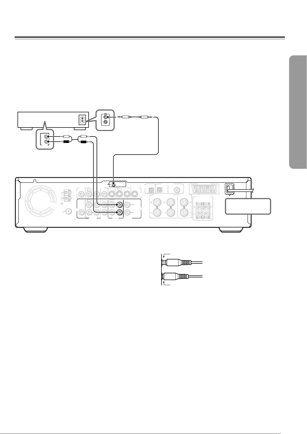
z Connection for the Onkyo MD
Recorder or Cassette Tape Deck
Onkyo MD recorder/HD
recorder/cassette tape deck
Notes
• If the connected component has two z connectors, you can use
either one to connect to the DVD Receiver. The other one can be
used to daisy chain with another component.
• Do not connect the Onkyo MD recorder, Hard Disk Recorder and
cassette tape deck with the z cable at the same time. This may
lead to unexpected operation.
• Connect the plugs securely.
• Be sure to connect to the z connectors using the z cable.
• The connections on pages 21 and 22 are needed even if z
connection is made.
• Do not connect the DVD Receiver’s z connector to any
component other than an Onkyo product. It may cause
malfunction.
DO NOT connect the
power cord (mains lead)
at this time.
The supplied remote controller has the following extended functions in addition to operating the DVD Receiver:
• Operating the TV and VCR (see pages 78-80)
• Operating the z connected Onkyo MD recorder, CD Recorder, Hard Disk Recorder or cassette tape deck (see page 41).
The z cable which is needed to make the z connection is supplied with the Onkyo MD recorder, CD Recorder, Hard Disk
Recorder or cassette tape deck.
If you start playing back the MD Recorder, CD Recorder, Hard Disk Recoder or cassette tape deck after making the z connection,
the DVD Receiver automatically changes its input source to TAPE/MD/HD — Direct Change function.
z cable
Be sure to connect
using the audio
connection cable.
Incomplete
Insert completely
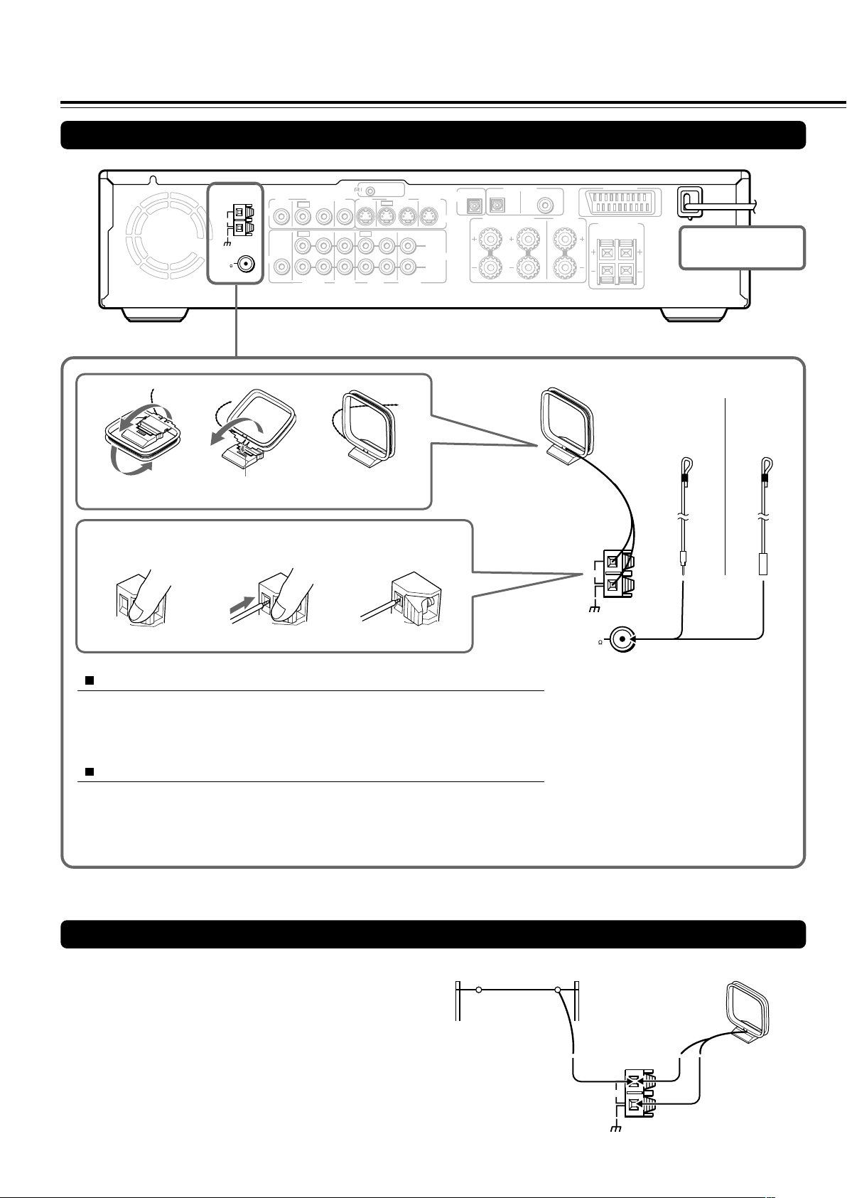
2424
REMOTE
CONTROL
OUT
2 ––VIDEO–– 1 VIDEO 2 VIDEO 1
IN
IN IN
IN
OUT
OUT
IN OUT IN
IN
IN
VIDEO2
CDR/PC
VIDEO 1 TAPE
MD/HD
TV/LINE
MON
OUT
MON
OUT
L
R
VIDEO
S VIDEO
AUDIO
SUB
WOOFER
PRE OUT
SURROUND
SPEAKERS
AUDIO
R
L
FRONT SPEAKERS CENTER
SPEAKER
R
L
FM
75
ANTENNA
DIGITAL
OUTPUT
DIGITAL INPUT
VIDEO 2 VIDEO 1
OPT
OPT
COAX
AM
AV
CONNECTOR
Connecting an AM Outdoor Antenna (Aerial)
Outdoor antenna (aerial)
AM indoor antenna (aerial)
Making Antenna (Aerial) Connections
Connecting the Supplied FM and AM Indoor Antennas (Aerials)
Press up and
hold the lever.
Insert the end of
the cord.
Release the lever to
secure the connection.
Adjusting the position of the FM indoor antenna (aerial)
While listening to an FM program (see page 38), extend the antenna (aerial) and
move it in various directions until the clearest signal is received, then secure the
antenna (aerial) with push pins in the position with the least distortion.
Adjusting the position of the AM indoor antenna (aerial)
While listening to an AM program (see page 38), set the antenna (aerial) in the
direction and position where you receive the clearest sound.
Put it as far away as possible from the unit, TVs, speaker cables, and power cords
(mains leads).
Note
Insert one end of the AM antenna
(aerial) cord to either of the AM antenna
(aerial) connectors and the other end to
the other connector. There is no
difference between one end of the AM
antenna (aerial) cord and the other end,
unlike the speaker cords which have
positive and negative poles.
ANTENNA
AM
AM indoor antenna (aerial)
Insert into the hole.
FM indoor antenna (aerial)
DO NOT connect the
power cord (mains lead)
at this time.
An outdoor antenna (aerial) will be more effective if it is stretched
horizontally above a window or outside.
Leave the supplied AM indoor antenna (aerial) connected.
Note
To avoid the risk of lightning and electrical shock, grounding is
necessary. Follow item 14 of the "Important Safeguards" on page 2 when
you install an outdoor antenna (aerial).
(North American
and South
American
models)
(Other
models)
FM
75
ANTENNA
AM
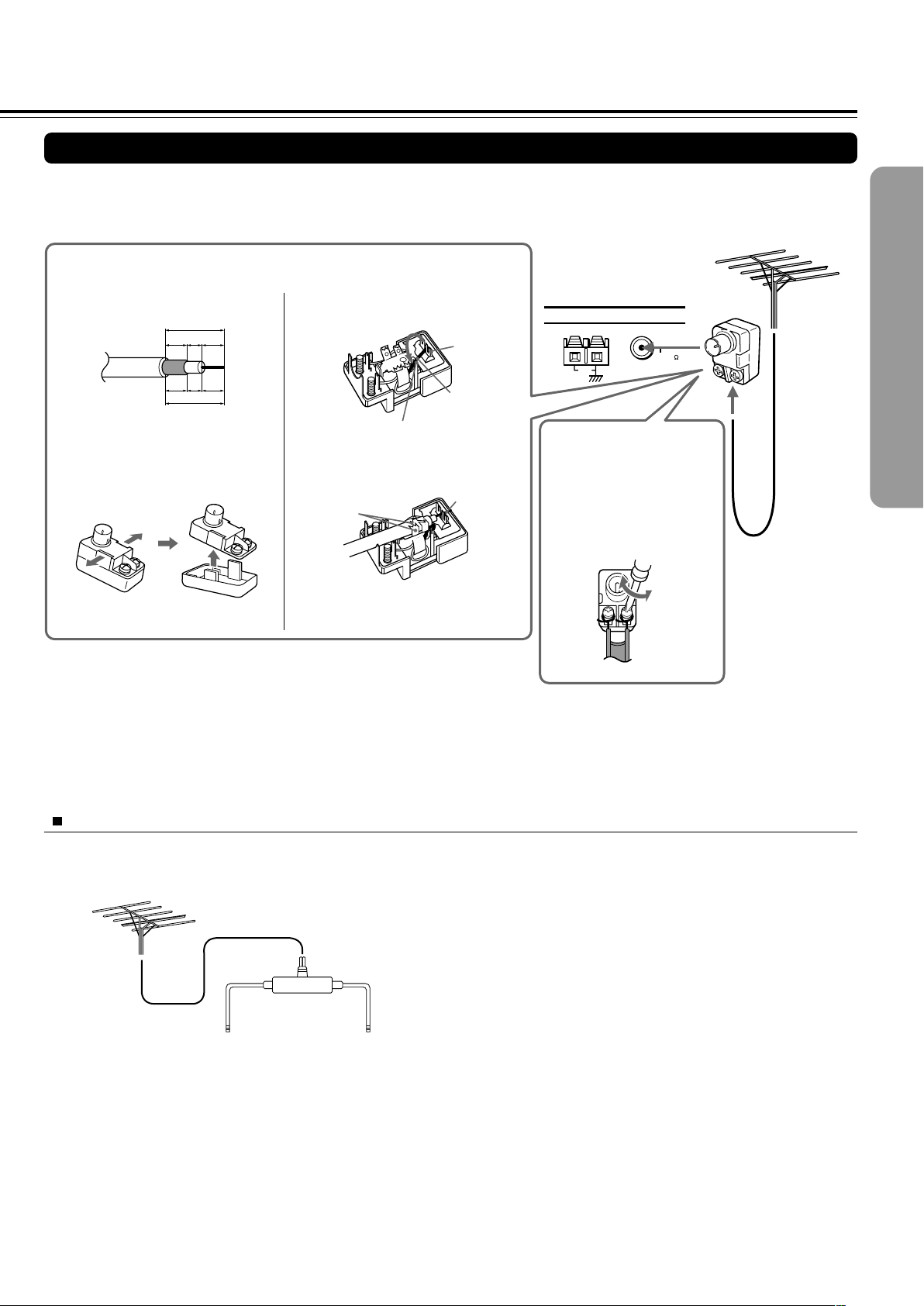
2525
FM 75
ANTENNA
AM
Connecting an FM Outdoor Antenna (Aerial)
If the FM reception is not very clear with the supplied antenna (aerial), connect an FM outdoor antenna (aerial) instead of the indoor
FM antenna (aerial).
Notes
• Install the antenna (aerial) well away from tall buildings and in an area where FM stations can directly be received.
• Keep the antenna (aerial) away from noise sources (neon signs, busy roads, etc.).
• It is dangerous to put the antenna (aerial) close to power lines. Keep it well away from power lines, transformers, etc.
• To avoid the risk of lightning and electrical shock, grounding is necessary. Follow item 14 of the “Important Safeguards” on page 2 when you install
the outdoor antenna (aerial).
Directional Iinkage
Do not use the same antenna (aerial) for both FM and TV (or VCR) reception since the FM and TV (or VCR) signals can interfere
with each other. If you must use a common FM/TV (or VCR) antenna (aerial), use a directional linkage type splitter.
Directional linkage
type splitter
To DVD Receiver To TV (or VCR)
FM outdoor antenna (aerial)
Connecting 300 ohm ribbon
wire to a 75/300 ohm
antenna (aerial) adapter*
Loosen the screws and wrap
the wire around these screws.
Then tighten the screws with
a screwdriver.
Tighten
Loosen
Connecting coaxial cable to a 75/300 ohm antenna (aerial) adapter*
3 Remove the transformer wire A
from slit B and insert it into slit C.
4 Insert the end of the cable.
5 Clamp it in place with pliers.
6 Reinstall the cover.
4
5
1 Strip the end of the coaxial cable.
2 With your fingernail or a small
screwdriver, press the stoppers
outward and remove the cover.
Slit B
Slit C
Wire A
15 mm
3
mm
6
mm
6
mm
5
/8 in.
1
/8
in.
1
/4
in.
1
/4
in.
* (North American
and European
models)
Not supplied
(Other models)
Supplied
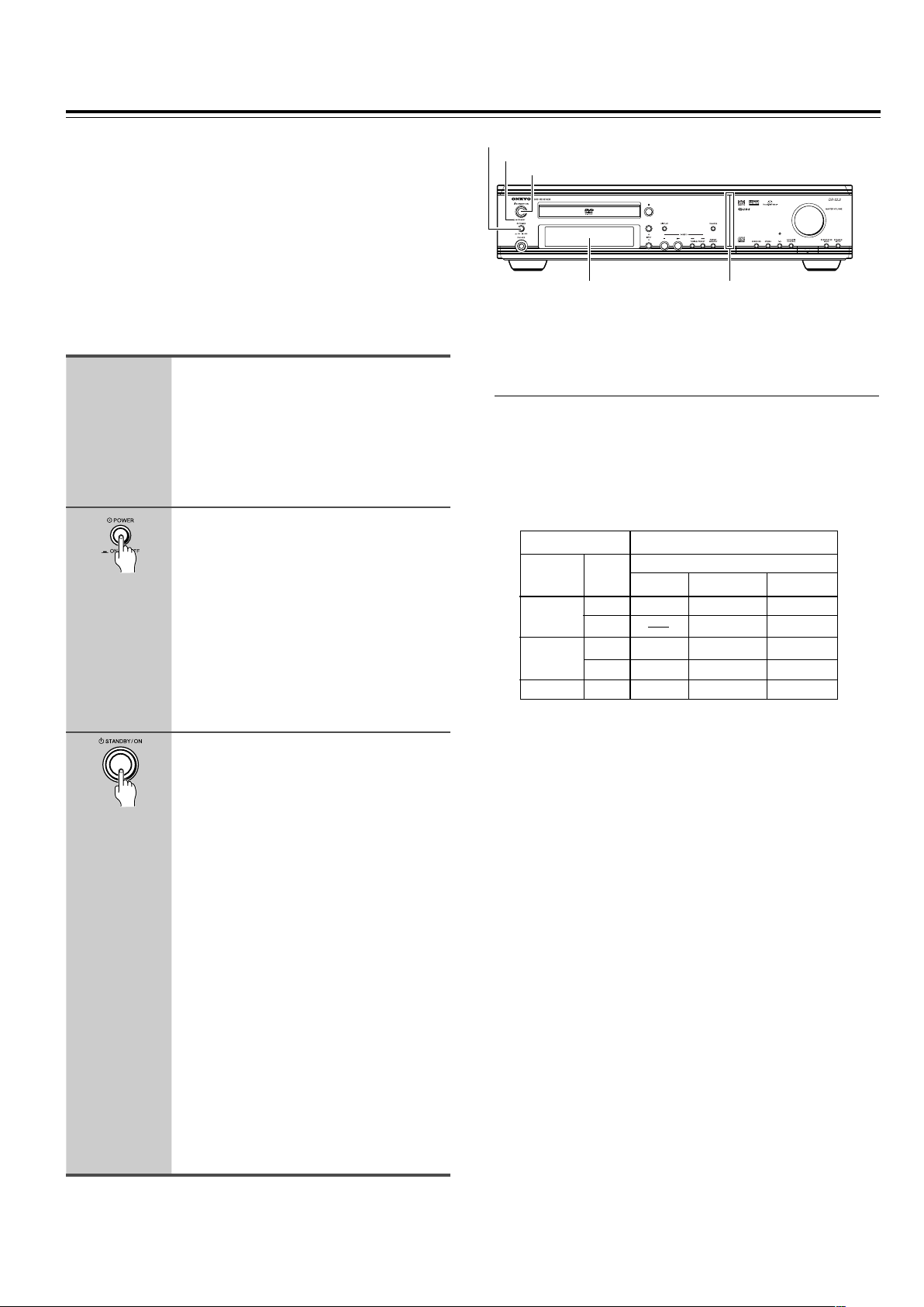
2626
Before connecting
• Make sure that all the connections from pages 15 to 25 are
complete (the connection to the TV is required).
• Turning on the DVD Receiver may cause a momentary power
surge, which might interfere with other electrical equipment such
as computers. If this happens, use a wall outlet on a different
circuit.
(European and some Asian models)
• The DVD Receiver is shipped with the main power (POWER)
switch in the on position (_ ON). When the power cord is
plugged in for the first time, the DVD Receiver will automatically
enter the standby state (same condition after step 2 below).
Connecting the Power/
Turning on the DVD Receiver
1
2
3
Connect the power cord to a wall
outlet.
(Other than European and some Asian
models)
The DVD Receiver enters the standby
mode and the STANDBY indicator lights
up.
(European and some Asian models
only)
Press POWER to switch on the
main power to put the DVD
Receiver in the standby mode.
The STANDBY indicator lights up.
• The buttons on the remote controller do
not operate if the POWER switch is set
to OFF.
• To switch off the main power, press
POWER again.
Press STANDBY/ON on the DVD
Receiver or ON on the remote
controller to turn on the DVD
Receiver.
The light and display on the DVD
Receiver’s front panel light. At the same
time, the STANDBY indicator goes off.
• To put the DVD Receiver in the standby
mode, press STANDBY/ON on the DVD
Receiver, or STANDBY on the remote
controller. Be sure to set the volume to
minimum before putting the DVD
Receiver in the standby mode for the
next use to avoid sudden loud sound
reproduction.
• While in the STANDBY mode, the DVD
Receiver can receive signals from the
remote controller. However, if you press
POWER on the DVD Receiver to switch
off the main power, the remote
controller cannot be used to turn on the
DVD Receiver.
• Setting the STANDBY button to standby
does not shut off the power completely.
■ Setting the TV System (Other than North
American model)
The default setting of the DVD Receiver is AUTO, and unless you
notice that the picture is distorted when playing some discs, you
should leave it set to AUTO.
If you experience picture distortion with some discs, set the TV
system to match your country or region’s system. Doing this,
however, may restrict the kinds of disc you can watch. The table
below shows what kinds of disc are compatible with each setting
(AUTO, PAL and NTSC).
1 Switch the DVD Receiver into standby.
2 Hold down ¢ then press STANDBY/ON until the display
indicates the new setting to switch the TV system.
The TV system changes as follows:
AUTO = NTSC
NTSC = PA L
PAL = AUTO
Note that you have to switch the player into standby before each
change.
About MOD. (Modulation) PAL
• SHRINK
Most models of the newly developed countdown PAL TV system
detect 50 Hz (PAL)/60 Hz (NTSC) and automatically switch
vertical amplitude, resulting in a display without vertical
shrinkage.
• If your PAL TV does not have a V-Hold control, you may not be
able to view NTSC disc because the picture may roll. If the TV
has a V-Hold control, adjust it until the picture stops rolling. On
some TVs, the picture may shrink vertically, leaving black bands
at the top and bottom of the screen. This is not a malfunction; it is
caused by the NTSC = PAL conversion.
Type
DVD
Video CD
CD, No disc
Format
NTSC
PAL
NTSC
PAL
Disc Output format
Position of TV SYSTEM mode
NTSC PAL AUTO
NTSC MOD. PAL NTSC
PAL PAL
NTSC MOD. PAL NTSC
NTSC PAL PAL
NTSC PAL NTSC or PAL
STANDBY indicator
STANDBY/ON
POWER
(European and some Asian models only)
Display Front panel
illumination
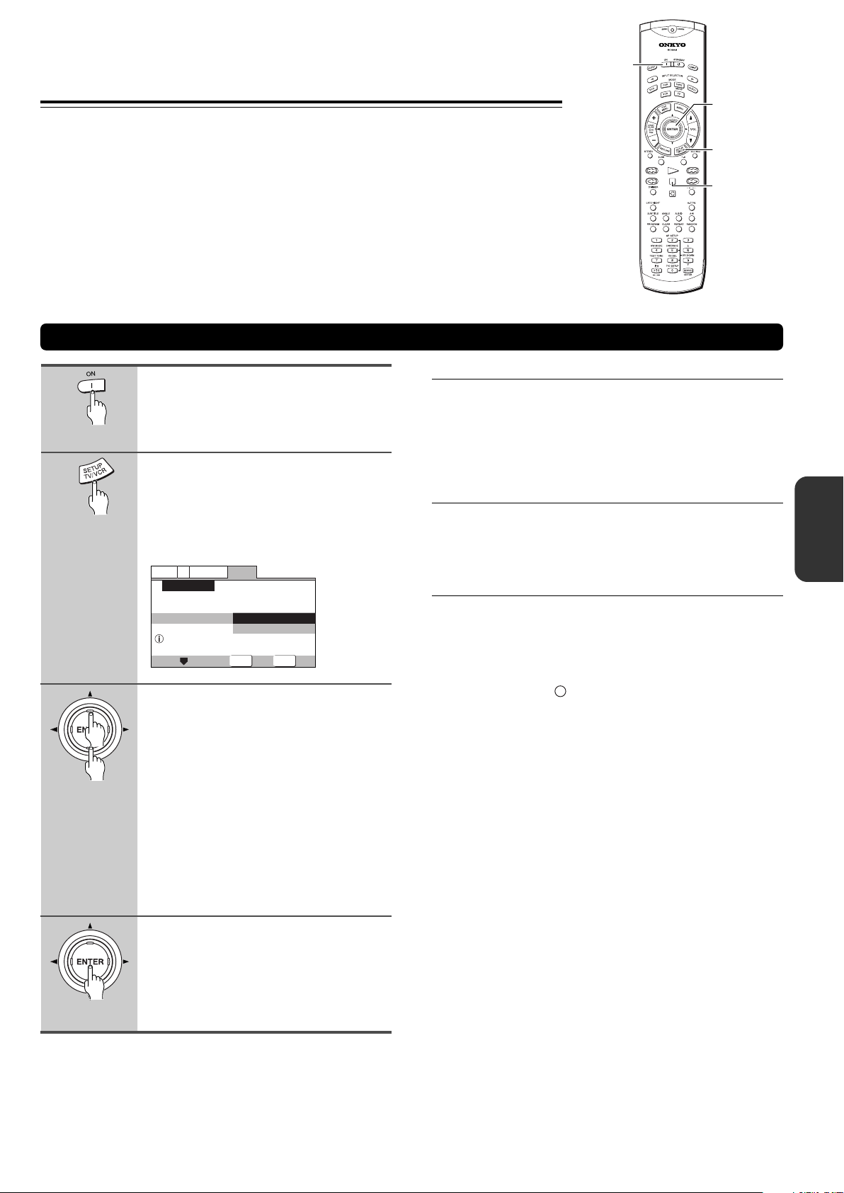
2727
SETUP
ENTER
General
V2
Language
Video1
Exit
Move
Select
Setup using the Setup Navigator
Setup Navigator
Setup Navigator
Start
Auto Start Off
Setting Up the DVD Receiver
The Setup Navigator has been designed to simplify the
process of getting the DVD Receiver ready to perform.
Designed as a series of on-screen multiple-choice questions,
the Setup Navigator automatically sets the video, and
language settings according to how the questions are
answered. Once this procedure is complete, it will be possible
to begin using the DVD Receiver to enjoy DVDs.
The procedure on this page describes the operations
necessary to function within the Setup Navigator screens. A
detailed description of the contents of each question that
appears on the screen can be found on the following pages.
Press ON (STANDBY/ON on the
front panel).
If there’s already a disc loaded and it starts
to play, press 7 to stop it.
Press SETUP.
When SETUP is pressed for the first time,
the following screen appears. Though the
Setup Navigator may be used more than
once, this screen only appears the first
time SETUP is pressed.
2
1
3
4
Using the Setup Navigator
Use the cursor buttons (5/∞) to
make a selection.
• If you are going to use the Setup
Navigator, it is not necessary to change
the setting on the first screen. Please
proceed to the next step.
• If you do not want to set up the DVD
Receiver using the Setup Navigator,
use the cursor button (∞) to select [Auto
Start Off] at this time.
The Setup Navigator function may still
be used at a later time in manual Setup
screen menu operation (page 64).
Press ENTER.
The selection is entered and the next
Setup Navigator screen appears.
Use steps 3 and 4 as a basis for entering
selections on the all of the Setup Navigator
screens described on the following pages.
■ When setting up for the first time
Some DVDs start playing automatically when loaded in the
DVD Receiver. Because the Setup Navigator cannot be used
if a disc is playing, it is recommended to set up the DVD
Receiver using the Setup Navigator before loading a DVD for
the first time. If a DVD has been loaded, be sure to press 7
before proceeding.
■ To change the answer to a prior question
Use the cursor button (2) to return to previous screens.
Please note, however, that you cannot go forward using the
cursor button (3), so it will be necessary to answer all the
questions that occur after the screen that was returned to.
■ To exit the Setup Navigator
Press SETUP while on any of the screens to exit the Setup
Navigator. Please note that if the Setup Navigator is exited
before all the questions are answered, no settings are
changed.
Note
On-screen information (
i
) appears to clarify the functions and
explain the options available.
2/3/5/∞
ENTER
7
SETUP
ON
 Loading...