


 CR-L5_E.book Page1 Monday, May19, 2003 4:05 PM
CD Receiver
CR-L5
Instruction Manual
Thank you for purchasing the Onkyo CD Receiver. Please read this manual thoroughly before making connections and turning on the power.
Following the instructions in this manual will enable you to obtain optimum performance and listening enjoyment from your new CD Receiver.
Please retain this manual for future reference.
Contents |
|
Introduction |
|
Important Safeguards .................................... |
2 |
Precautions .................................................... |
4 |
Features ......................................................... |
5 |
Supplied Accessories .................................... |
6 |
Disc Notes ..................................................... |
6 |
Before Using the CR-L5 ............................... |
7 |
Controls & Connectors.................................. |
8 |
Connections |
|
Connecting Your Other Components to the |
|
CR-L5 ...................................................... |
11 |
Connecting -compatible Components ... |
12 |
Connecting Your Speakers.......................... |
13 |
Connecting Antenna.................................... |
14 |
Setting the Clock |
|
Powering Up and Setting the Clock ............ |
16 |
Operation |
|
Using the CR-L5 ......................................... |
19 |
Playing CDs ................................................ |
20 |
Using the Radio........................................... |
22 |
Other Functions ........................................... |
25 |
Timers ......................................................... |
26 |
Appendix |
|
Troubleshooting .......................................... |
29 |
Specifications .............................................. |
32 |
En
 CR-L5_E.book Page 2 Monday, May19, 2003 4:05 PM
WARNING:
TO REDUCE THE RISK OF FIRE OR ELECTRIC SHOCK, DO NOT EXPOSE THIS APPLIANCE TO RAIN OR MOISTURE.
CAUTION:
TO REDUCE THE RISK OF ELECTRIC SHOCK, DO NOT REMOVE COVER (OR BACK). NO USER-SERVICEABLE PARTS INSIDE. REFER SERVICING TO QUALIFIED SERVICE PERSONNEL.
WARNING |
|
AVIS |
RISK OF ELECTRIC SHOCK |
|
RISQUE DE CHOC ELECTRIQUE |
DO NOT OPEN |
|
NE PAS OUVRIR |
The lightning flash with arrowhead symbol, within an equilateral triangle, is intended to alert the user to the presence of uninsulated “dangerous voltage” within the product’s enclosure that may be of sufficient magnitude to constitute a risk of electric shock to persons.
The exclamation point within an equilateral triangle is intended to alert the user to the presence of important operating and maintenance (servicing) instructions in the literature accompanying the appliance.
Important Safeguards
1.Read Instructions—All the safety and operating instructions should be read before the appliance is operated.
2.Retain Instructions—The safety and operating instructions should be retained for future reference.
3.Heed Warnings—All warnings on the appliance and in the operating instructions should be adhered to.
4.Follow Instructions—All operating and use instructions should be followed.
5.Cleaning—Unplug the appliance from the wall outlet before cleaning. The appliance should be cleaned only as recommended by the manufacturer.
6.Attachments—Do not use attachments not recommended by the appliance manufacturer as they may cause hazards.
7.Water and Moisture—Do not use the appliance near water –for example, near a bath tub, wash bowl, kitchen sink, or laundry tub; in a wet basement; or near a swimming pool; and the like.
8.Accessories—Do not place the appliance on an unstable cart, stand, tripod, bracket, or table. The appliance may fall, causing serious injury to a child or adult, and serious damage to the appliance. Use only with a cart, stand, tripod, bracket, or table recommended by the manufacturer, or sold with the appliance. Any mounting of the appliance should follow the manufacturer’s instructions, and should use a mounting accessory recommended by the manufacturer.
9. An appliance and cart combination should be moved with care. Quick stops, excessive force, and uneven surfaces may cause the appliance and
cart combination to overturn.
S3125A
10.Ventilation—Slots and openings in the cabinet are pro-
vided for ventilation and to ensure reliable operation of the appliance and to protect it from overheating, and these openings must not be blocked or covered. The openings should never be blocked by placing the appliance on a bed, sofa, rug, or other similar surface. The appliance should not be placed in a built-in installation such as a bookcase or rack unless proper ventilation is provided. There should be free space of at least 8 in. (20 cm) and an opening behind the appliance.
2
11.Power Sources—The appliance should be operated only from the type of power source indicated on the marking label. If you are not sure of the type of power supply to your home, consult your appliance dealer or local power company.
12.Grounding or Polarization—The appliance may be equipped with a polarized alternating current line plug (a plug having one blade wider than the other). This plug will fit into the power outlet only one way. This is a safety feature. If you are unable to insert the plug fully into the outlet, try reversing the plug. If the plug should still fail to fit, contact your electrician to replace your obsolete outlet. Do not defeat the safety purpose of the polarized plug.
13.Power Cord Protection—Power-supply cords should be routed so that they are not likely to be walked on or pinched by items placed upon or against them, paying particular attention to cords at plugs, convenience receptacles, and the point where they exit from the appliance.
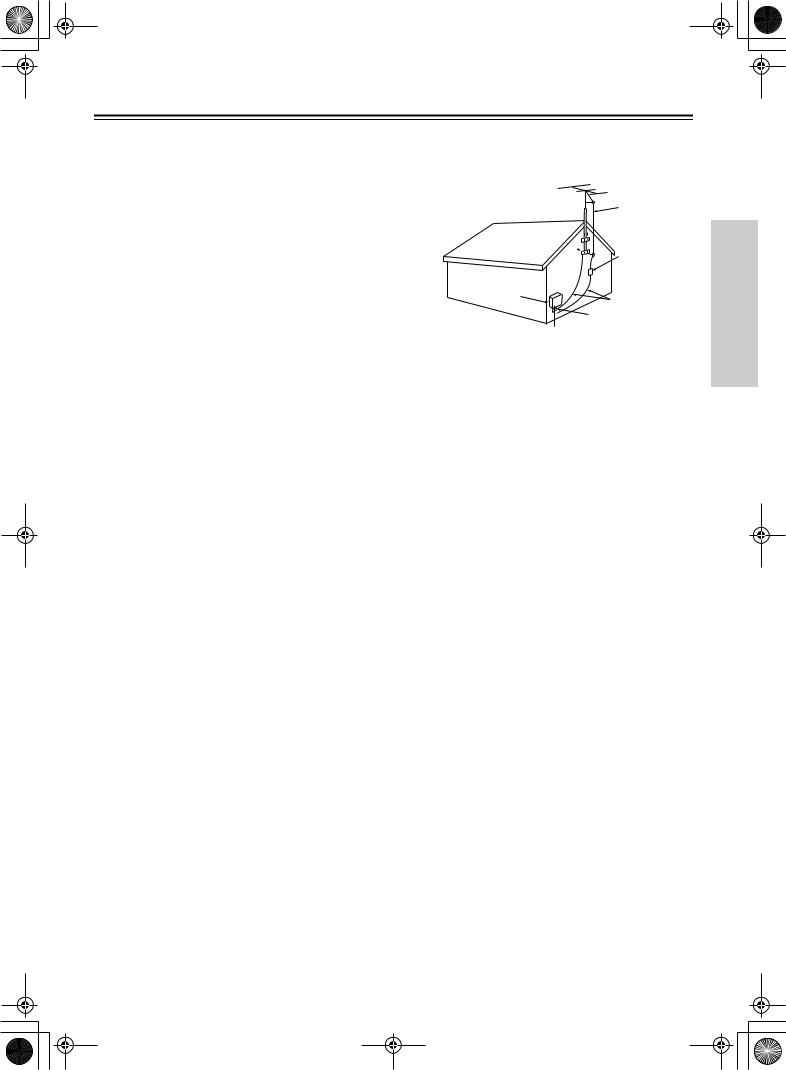
14. Outdoor Antenna Grounding—If an outside antenna or cable system is connected to the appliance, be sure the antenna or cable system is grounded so as to provide some protection against voltage surges and built-up static charges. Article 810 of the National Electrical Code, ANSI/NFPA 70, provides information with regard to proper grounding of the mast and supporting structure, grounding of the lead-in wire to an antennadischarge unit, size of grounding conductors, location of antenna-discharge unit, connection to grounding electrodes, and requirements for the grounding electrode. See Figure 1.
15.Lightning—For added protection for the appliance during a lightning storm, or when it is left unattended and unused for long periods of time, unplug it from the wall outlet and disconnect the antenna or cable system. This will prevent damage to the appliance due to lightning and power-line surges.
16. Power Lines—An outside antenna system should not be located in the vicinity of overhead power lines or other electric light or power circuits, or where it can fall into such power lines or circuits. When installing an outside antenna system, extreme care should be taken to keep from touching such power lines or circuits as contact with them might be fatal.
17.Overloading—Do not overload wall outlets, extension cords, or integral convenience receptacles as this can result in a risk of fire or electric shock.
 CR-L5_E.book Page 3 Monday, May19, 2003 4:05 PM
Important Safeguards—Continued
18.Object and Liquid Entry—Never push objects of any kind into the appliance through openings as they may touch dangerous voltage points or short-out parts that could result in a fire or electric shock. Never spill liquid of any kind on the appliance.
19.Servicing—Do not attempt to service the appliance yourself as opening or removing covers may expose you to dangerous voltage or other hazards. Refer all servicing to qualified service personnel.
20.Damage Requiring Service—Unplug the appliance form the wall outlet and refer servicing to qualified service personnel under the following conditions:
A.When the power-supply cord or plug is damaged,
B.If liquid has been spilled, or objects have fallen into the appliance,
C.If the appliance has been exposed to rain or water,
D.If the appliance does not operate normally by following the operating instructions. Adjust only those controls that are covered by the operating instructions as an improper adjustment of other controls may result in damage and will often require extensive work by a qualified technician to restore the appliance to its normal operation,
E.If the appliance has been dropped or damaged in any way, and
F.When the appliance exhibits a distinct change in performance – this indicates a need for service.
21.Replacement Parts—When replacement parts are required, be sure the service technician has used replacement parts specified by the manufacturer or have the same characteristics as the original part. Unauthorized substitutions may result in fire, electric shock, or other hazards.
22.Safety Check—Upon completion of any service or repairs to the appliance, ask the service technician to perform safety checks to determine that the appliance is in proper operation condition.
23.Wall or Ceiling Mounting—The appliance should be mounted to a wall or ceiling only as recommended by the manufacturer.
24.Heat—The appliance should be situated away from heat sources such as radiators, heat registers, stoves, or other appliances (including amplifiers) that produce heat.
25.Liquid Hazards—The appliance should not be exposed to dripping or splashing and no objects filled with liquids, such as vases should be placed on the appliance.
FIGURE 1:
EXAMPLE OF ANTENNA GROUNDING AS PER NATIONAL ELECTRICAL CODE, ANSI/NFPA 70
ANTENNA
LEAD IN
WIRE
GROUND  CLAMP
CLAMP 
ANTENNA DISCHARGE UNIT (NEC SECTION 810-20)
ELECTRIC
SERVICE
EQUIPMENT
GROUNDING CONDUCTORS (NEC SECTION 810-21)

 GROUND CLAMPS

 POWER SERVICE GROUNDING NEC – NATIONAL ELECTRICAL CODE ELECTRODE SYSTEM
(NEC ART 250, PART H)
S2898A
3
 CR-L5_E.book Page 4 Monday, May19, 2003 4:05 PM
Precautions
1.Recording Copyright
Unless it’s for personal use only, recording copyrighted material is illegal without the permission of the copyright holder.
2.AC Fuse
The AC fuse inside the CR-L5 is not user-serviceable. If you cannot turn on the CR-L5, contact your Onkyo dealer.
3.Care
Occasionally you should dust the CR-L5 all over with a soft cloth. For stubborn stains, use a soft cloth dampened with a weak solution of mild detergent and water. Dry the CR-L5 immediately afterwards with a clean cloth. Don’t use abrasive cloths, thinners, alcohol, or other chemical solvents, because they may damage the finish or remove the panel lettering.
4.Power WARNING
BEFORE PLUGGING IN THE UNIT FOR THE FIRST TIME, READ THE FOLLOWING SECTION CAREFULLY.
AC outlet voltages vary from country to country. Make sure that the voltage in your area meets the voltage requirements printed on the CR-L5’s rear panel (AC 230 V, 50 Hz).
Setting the [STANDBY/ON] switch to STANDBY does not fully shutdown the CR-L5. If you do not intend to use the CR-L5 for an extended period, remove the power cord from the AC outlet.
5.Never Touch This Unit with Wet Hands
Never handle this unit or its power cord while your hands are wet or damp. If water or any other liquid gets inside this unit, have it checked by your Onkyo dealer.
6.Installing This Unit
•Install this unit in a well-ventilated location.
•Ensure that there’s adequate ventilation all around this unit, especially if it’s installed in an audio rack. If the ventilation is inadequate, the unit may overheat, leading to malfunction.
•Do not expose this unit to direct sunlight or heat sources, because its internal temperature may rise, shortening the life of the optical pickup.
•Avoid damp and dusty places, and places subject to vibrations from loudspeakers. Never put the unit on top of, or directly above a loudspeaker.
•Install this unit horizontally. Never use it on its side or on a sloping surface, because it may cause a malfunction.
•If you install this unit near a TV, radio, or VCR, the sound quality may be affected. If this occurs, move this unit away from the TV, radio, or VCR.
7.Moisture Condensation
Moisture condensation may damage this unit.
Read the following carefully:
When you take a glass containing a cold drink outside on a summer’s day, drops of water, called condensation, form on the outside of the glass. Similarly, moisture may condense on the lens of the optical pickup, one of the most important parts inside this unit.
•Moisture condensation can occur in the following situations:
—The unit is moved from a cold place to a warm place.
—A heater is turned on, or cold air from an air conditioner is hitting the unit.
—In the summer, when this unit is moved from an air conditioned room to a hot and humid place.
—The unit is used in a humid place.
•Do not use this unit when there’s the possibility of moisture condensation occurring. Doing so may damage your discs and certain parts inside this unit.
If condensation does occur, remove all discs and leave this unit turned on for two to three hours. By this time, the unit will have warmed up and any condensation will have evaporated. To reduce the risk of condensation, keep this unit connected to a wall outlet.
For British models
Replacement and mounting of an AC plug on the power supply cord of this unit should be performed only by qualified service personnel.
IMPORTANT
The wires in the mains lead are coloured in accordance with the following code:
Blue: Neutral
Brown: Live
As the colours of the wires in the mains lead of this apparatus may not correspond with the coloured markings identifying the terminals in your plug, proceed as follows:
The wire which is coloured blue must be connected to the terminal which is marked with the letter N or coloured black.
The wire which is coloured brown must be connected to the terminal which is marked with the letter L or coloured red.
IMPORTANT
A 5 ampere fuse is fitted in this plug. Should the fuse need to be replaced, please ensure that the replacement fuse has a rating of 5 amperes and that it is approved by ASTA or BSI to BS1362. Check for the ASTA mark or the BSI mark on the body of the fuse.
IF THE FITTED MOULDED PLUG IS UNSUITABLE FOR THE SOCKET OUTLET IN YOUR HOME THEN THE FUSE SHOULD BE REMOVED AND THE PLUG CUT OFF AND DISPOSED OF SAFELY. THERE IS A DANGER OF SEVERE ELECTRICAL SHOCK IF THE CUT OFF PLUG IS INSERTED INTO ANY 13 AMPERE SOCKET.
If in any doubt, consult a qualified electrician.
4
 CR-L5_E.book Page 5 Monday, May19, 2003 4:05 PM
Precautions—Continued
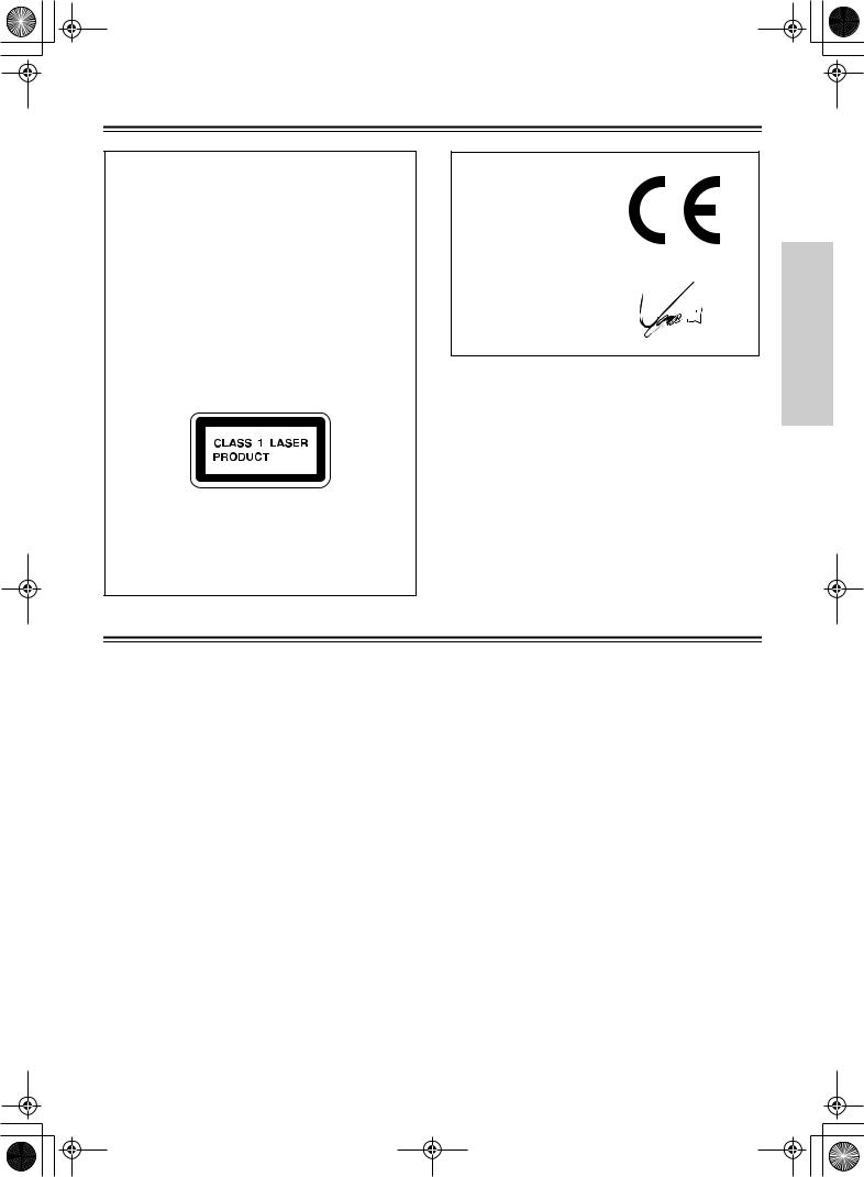
This unit contains a semiconductor laser system and is classified as a “CLASS 1 LASER PRODUCT.” So, to use this model properly, read this Instruction Manual carefully. In case of any trouble, please contact the store where you purchased the unit. To prevent exposure to the laser beam, do not try to open the enclosure.
DANGER:
VISIBLE AND INVISIBLE LASER RADIATION WHEN OPEN AND INTERLOCK FAILED OR DEFEATED. DO NOT STARE INTO BEAM.
CAUTION:
THIS PRODUCT UTILIZES A LASER. USE OF CONTROLS OR ADJUSTMENTS OR PERFORMANCE OF PROCEDURES OTHER THAN THOSE SPECIFIED HEREIN MAY RESULT IN HAZARDOUS RADIATION EXPOSURE.
This label is located on the rear panel. It indicates that:
1.This unit is a CLASS 1 LASER PRODUCT and employs a laser inside the cabinet.
2.To prevent the laser from being exposed, do not remove the cover. Refer servicing to qualified personnel.
Declaration of Conformity
We, ONKYO EUROPE ELECTRONICS GmbH LIEGNITZERSTRASSE 6, 82194 GROEBENZELL, GERMANY
declare in own responsibility, that the ONKYO product described in this instruction manual is in compliance with the corresponding technical standards such as EN60065, EN55013, EN55020 and EN61000-3-2, -3-3.
GROEBENZELL, GERMANY
I. MORI
ONKYO EUROPE ELECTRONICS GmbH
Memory backup
The CR-L5 uses a battery-less memory backup system in order to retain radio presets and other settings when it’s unplugged or in the case of a power failure. Although no batteries are required, the CR-L5 must be plugged into an AC outlet in order to charge the backup system.
Once it has been charged, the CR-L5 will retain the settings for several weeks, although this depends on the environment and will be shorter in humid climates. The clock setting is not retained by the backup system.
Features
•2 × 50 watts at 4 Ω, 1 kHz, DIN
•4 Ω speaker drive capability
•WRAT (Wide Range Amplifier Technology)*1
•VLSC (Vector Linear Shaping Circuitry)*2
•Direct mode
•
 full-function remote control
•4 timers for auto playback or recording
•3-level display dimmer
•Optical and coaxial digital outputs
•Subwoofer preout
•CDR and TAPE inputs/outputs
•A and B speaker outputs (Binding-post speaker terminals)
•RDS (Radio Data System), including PS (Program Service Name), RT (Radio Text), and CT (Clock Time)
•40 radio presets
*1. Wide Range Amplifier Technology improves the imaging, realism, and accuracy of sound material. *2. A proprietary Onkyo D/A converter, featuring Pulse Noise Reduction.
5
 CR-L5_E.book Page 6 Monday, May19, 2003 4:05 PM
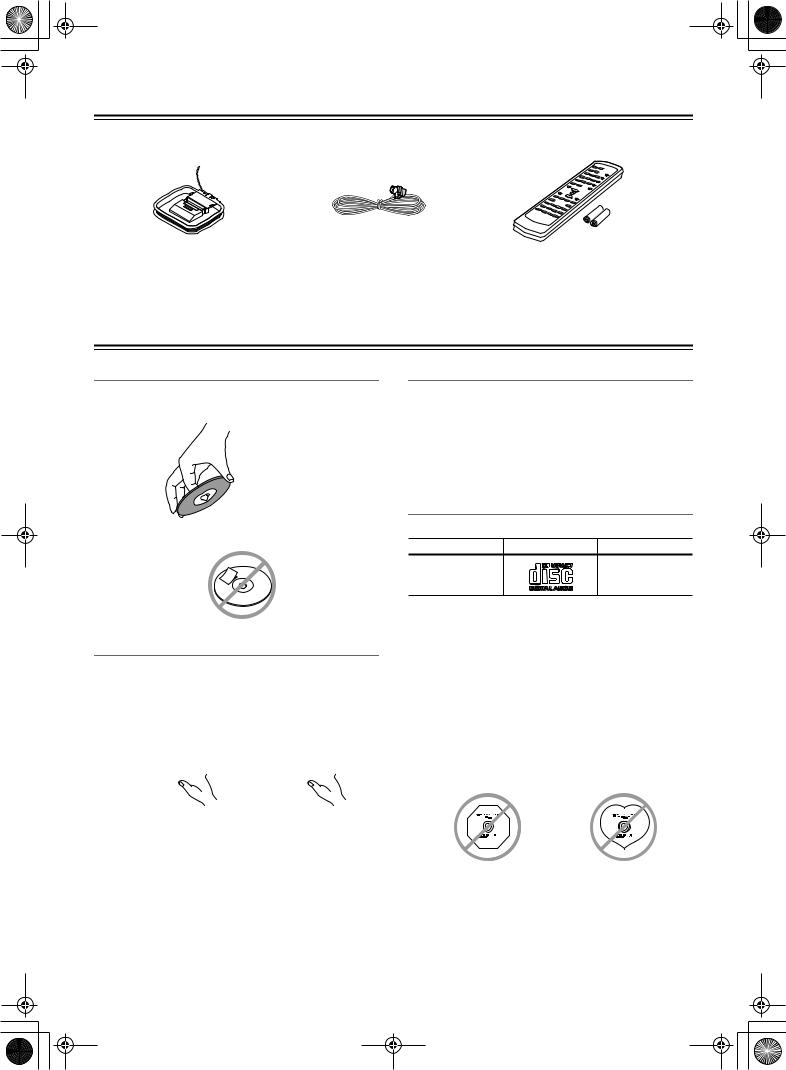
Supplied Accessories
Check that the following accessories are supplied with this unit.
AM loop antenna |
FM indoor antenna |
Remote controller (RC-535S) |
|
|
two batteries (AA/R6) |
*In catalogs and on packaging, the letter added to the end of the product name indicates the color of the CR-L5. Specifications and operation are the same regardless of color.
Disc Notes
Handling Discs
•Never touch the underside of a disc. Always hold discs by the edge, as shown.
 Underside
• Never attach adhesive tape or sticky labels to discs.
Cleaning Discs
•For best results, keep your discs clean. Fingerprints and dust can affect the sound quality and should be removed as follows. Using a clean soft cloth, wipe from the center outwards, as shown. Never wipe in a circular direction.


•To remove stubborn dust or dirt, wipe the disc with a damp soft cloth, and then dry it with a dry cloth.
•Never use solvent-based cleaning fluids, such as thinner or benzine, commercially available cleaners, or antistatic sprays intended for vinyl records, because they may damage the disc.
Storing Discs
•Don’t store discs in places subject to direct sunlight, or near heat sources.
•Don’t store discs in places subject to moisture or dust, such as in a bathroom or near a humidifier.
•Always store discs in their cases and vertically. Stacking, or putting objects on unprotected discs may cause warping, scratches, or other damage.
Supported Discs
The CR-L5 supports the following discs.
Disc |
Logo |
Format |
Audio CD |
|
PCM audio |
About playing copy-controlled CDs
Some audio CDs feature copy protection that doesn’t conform to the official CD standard. Since these are nonstandard discs, they may not play properly in the CR-L5.
•The CR-L5 does not support disc types not listed.
•The CR-L5 does not support the following disc types even if they bear the logo shown above: CD-R, CD-RW, CD-ROM, Super Audio CD, Photo CD, CD-G.
•The CR-L5 supports 8 cm and 12 cm discs.
•Don’t use discs with an unusual shape, such as those shown below, because you may damage the CR-L5.
•Don’t use discs that have residue from adhesive tape, rental discs with peeling labels, or discs with custommade labels or stickers. Doing so may damage the CR-L5 and you may not be able to remove the disc properly.
6
 CR-L5_E.book Page 7 Monday, May19, 2003 4:05 PM
Before Using the CR-L5
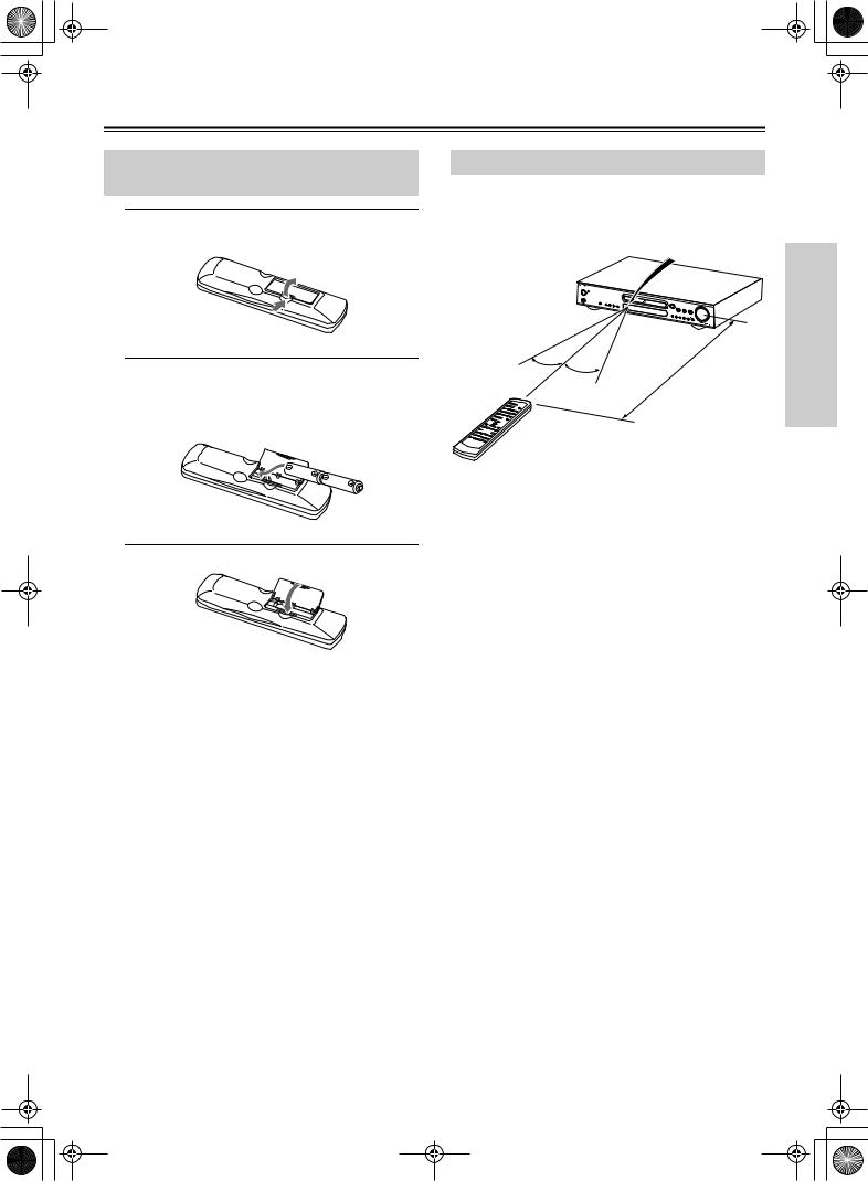
Installing the Remote Controller
Batteries
1 Open the battery compartment, as shown.
Using the Remote Controller
To use the remote controller, point it at the CR-L5’s remote control sensor, as shown below.
Remote control sensor
CR-L5
2 Insert the two supplied batteries (AA/
R6) in accordance with the polarity diagram inside the battery compartment.
30˚
30˚
|
|
|
) |
|
|
|
. |
|
|
(16 |
ft |
|
m |
|
|
5 |
|
|
|
|
|
|
|
. |
|
|
|
Approx |
|
|
|
3 Close the battery compartment.
Notes:
•The supplied batteries should last for about six months, although this will vary with usage.
•If the remote controller doesn’t work reliably, try replacing both batteries.
•Don’t mix new and old batteries, or different types of batteries.
•If you intend not to use the remote controller for a long time, remove the batteries to prevent possible leakage and corrosion.
•Flat batteries should be removed as soon as possible to prevent possible leakage and corrosion.
Notes:
•The remote controller may not work reliably if the CR-L5 is subjected to bright light, such as direct sunlight or inverter-type fluorescent lights. Keep this in mind when installing the CR-L5.
•If another remote controller of the same type is used in the same room, or the CR-L5 is installed close to equipment that uses infrared rays, the remote controller may not work reliably.
•Don’t put anything, such as a book, on the remote controller, because the buttons may be pressed inadvertently, thereby draining the batteries.
•The remote controller may not work reliably if the CR-L5 is installed in a rack behind colored glass doors. Keep this in mind when installing the CR-L5.
•The remote controller will not work if there’s an obstacle between it and the CR-L5’s remote control sensor.
7

 CR-L5_E.book Page 8 Monday, May19, 2003 4:05 PM
Controls & Connectors
Front Panel
For detailed information, refer to the pages in parenthesis.
1 2 |
|
|
Disc Tray |
3 |
4 |
5 |
|
|
|
|
|
|
VOLUME |
STANDBY / ON |
|
|
|
|
|
|
STANDBY |
|
|
|
PAUSE |
STOP |
PLAY |
PHONES |
|
|
|
|
INPUT |
DIRECT |
|
SPEAKERS A / B MEMORY FM MODE |
|
|
DISPLAY |
||
|
|
|
|
|
||
|
CLEAR TUNING |
|
|
PRESET |
|
|
6 |
7 89 J |
K |
Display |
L M |
N O |
|
A STANDBY/ON button (16) |
|
I FM MODE button (22–23) |
|
|||
Sets the CR-L5 to On or Standby. |
|
|
Used to select stereo or mono for FM radio. |
|||
BSTANDBY indicator (16)
Lights up when the CR-L5 is in Standby mode. It also lights up when the CR-L5 receives signals from the remote controller.
C[ ] button (20)
Opens and closes the disc tray.
DPAUSE [
 ], STOP [
 ] & PLAY [
 ] buttons (20)
Used to pause, stop, and start playback.
EVOLUME control (19)
Adjusts the volume.
FPHONES jack (19)
Used to connect a pair of stereo headphones.
GSPEAKERS A/B button (19)
Turns speaker sets A and B on and off.
HMEMORY button (22–24)
Used to store radio presets.
J [  ] & [
] & [ ] buttons (TUNING [ ] & [ ] buttons)
(20, 22)
Used for fast reverse and fast forward when playing CDs, or tuning when using the radio.
KRemote control sensor (7)
Receives control signals from the remote controller.
LDISPLAY button (16, 17, 20, 22–24)
Used to change the displayed information.
M[ ] & [
] & [
 ] buttons (PRESET [ ] & [ ] buttons) (20–24)
Used to select the previous or next track when playing CDs, or to select presets when using the radio.
NINPUT [ ] [ ] selector buttons (19, 22)
Used to select sound sources: CD, CD-R, TAPE, TV/ LINE, FM or AM.
ODIRECT button & indicator (25)
Used to select Direct mode.
Display
For detailed information, refer to the pages in parenthesis.
1 2 3 4 |
5 |
6 7 8 9 0 A |
||||
|
|
|
|
|
|
|
|
|
|
|
|
|
|
|
|
|
|
|
|
|
|
|
|
|
|
|
|
|
|
|
|
|
|
|
B C D
8
 CR-L5_E.book Page 9 Monday, May19, 2003 4:05 PM
Controls & Connectors—Continued
1TRACK indicator
Appears when the CD input source is selected.
2MEMORY indicator (21)
Lights up when memory playback is used.
3RANDOM indicator (21)
Lights up when random playback is used.
4REPEAT indicator (21)
Lights up when repeat playback is used.
5FM STEREO indicator (22)
Lights up when tuned to a stereo FM station.
6AUTO indicator (22)
Lights up when auto stereo tuning is used.
7Tuned indicator (22)
Lights up when the CR-L5 is properly tuned to a radio station.
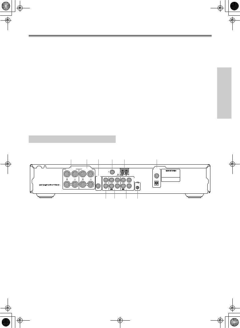
Rear Panel
For detailed information, refer to the pages in parenthesis.
8MUTING indicator (25)
Lights up when the CR-L5 is muted.
9RDS indicator (17, 23)
Lights up when the CR-L5 is tuned to a radio station that supports RDS (Radio Data System).
0A & B speaker indicators (19)
Indicator A lights up when speaker set A is on. Indicator B lights up when speaker set B is on.
ASLEEP indicator (28)
Lights up when the Sleep function has been set.
BMessage area
Various information is displayed here.
CPlay/Pause  /
/
 indicators (20)
Light up for playback and pause.
DTIMER indicators (27)
Light up when a timer has been set.
1 |
2 |
3 |
4 |
5 |
6 |
SPEAKERS A |
SPEAKERS B |
ANTENNA |
|
|
|
L |
|
L |
FM 75 |
|
|
|
|
|
|
|
|
|
|
SUB |
|
|
AM |
|
|
TV/LINE |
TAPE |
CDR |
|
|
|
WOOFER |
|||
|
|
|
|
|
|
|
PREOUT |
L |
|
|
|
AUDIO |
R |
R |
|
|
|
L ANALOG |
|
|
|
|
|
|
||
|
|
|
|
|
|
REMOTE |
|
|
R |
|
|
|
CONTROL |
A OR B: 4 OHMS MIN. / SPEAKER |
|
|
|
|
R |
|
A+B: 8 OHMS MIN. / SPEAKER |
|
IN |
|
IN |
|
IN |
|
|
OUT |
OUT |
AUDIO
OUTPUT
DIGITAL
COAXIAL |
CD RECEIVER |
|
MODEL NO. CR-L5 |
OPTICAL
7 8 9 J
ASPEAKERS A (13)
These terminal posts are for connecting speaker set A.
BSPEAKERS B (13)
These terminal posts are for connecting speaker set B.
CSUBWOOFER PREOUT (13)
This RCA/phono connector can be used to connect an active subwoofer. The subwoofer output is turned on and off with speaker set A.
DFM 75Ω ANTENNA (14, 15)
This connector is for connecting an FM antenna.
EAM ANTENNA (14, 15)
These push terminals are for connecting an AM antenna.
FCOAXIAL & OPTICAL DIGITAL AUDIO OUTPUT (11)
These connectors can be used to connect a CD recorder or other component with digital inputs.
GTV/LINE IN (11)
These RCA/phono connectors can be used to connect a TV or other component.
HTAPE IN/OUT (11)
These RCA/phono connectors can be used to connect a cassette tape deck or other recorder with analog inputs and outputs.
ICDR IN/OUT (11)
These RCA/phono connectors can be used to connect a CD recorder or other recorder with analog inputs and outputs.
J REMOTE CONTROL (12)
This  (Remote Interactive) connector can be connected to the
  connector on another Onkyo component. To use
 , you must make an analog RCA/phono connection between the CR-L5 and your other component, even if they are connected digitally.
9
 CR-L5_E.book Page 10 Monday, May 19,2003 4:05 PM
Controls & Connectors—Continued
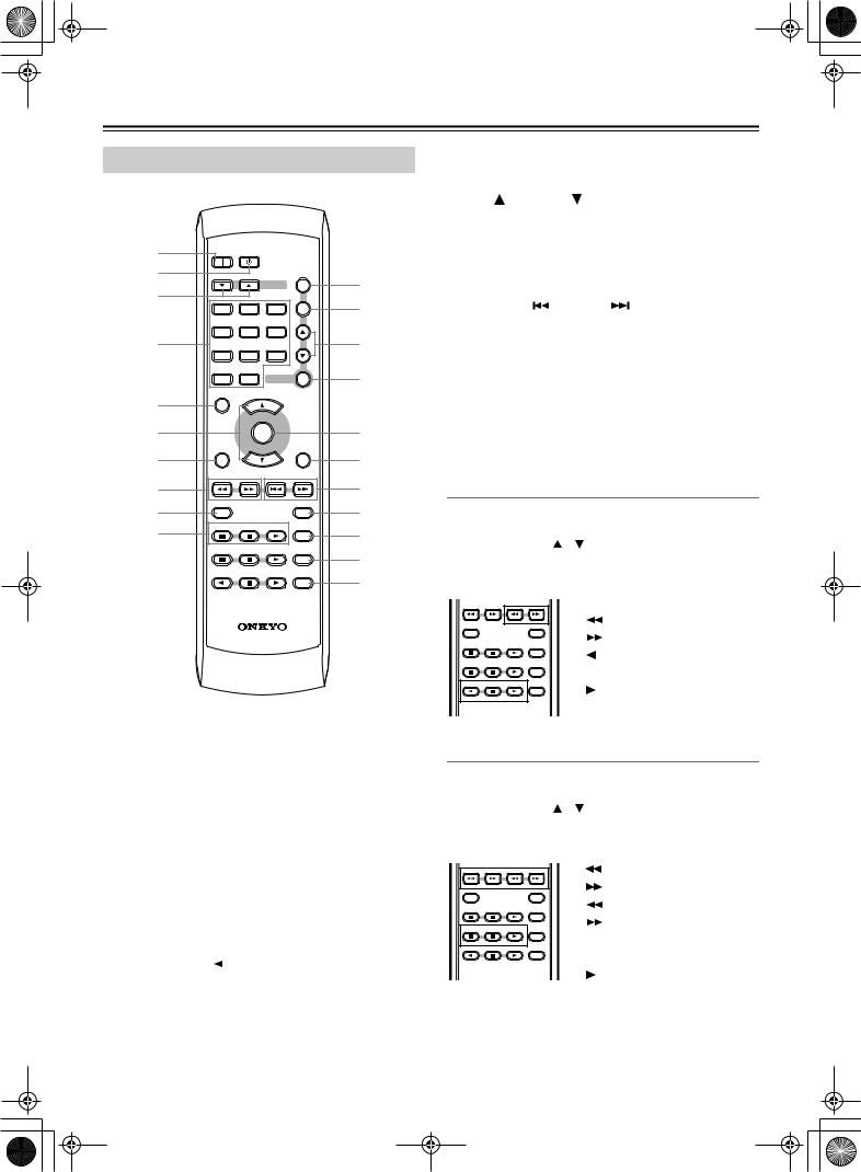
Remote Controller |
|
|
K TONE button— Used to set the tone. |
||
|
|
L TIMER button— Used to set the timers. |
|||
|
|
|
|
|
|
|
|
|
|
|
M Up [ ] & Down [ ] buttons— Used to set the tim- |
|
|
|
|
|
ers and tone. |
1 |
|
|
|
|
N ENTER button— Used to set the timers and tone. |
ON |
STANDBY |
|
|
O MUTING button— Used to mute the CR-L5. |
|
2 |
|
|
|
|
|
|
|
|
TONE |
P DIRECT button— Used to select Direct mode. |
|
3 |
|
INPUT |
K |
||
|
|
|
|
||
|
|
|
TIMER |
Q Previous [ ] & Next [ ] buttons— Used to |
|
|
1 |
2 |
3 |
L |
|
|
|
|
|
select the previous or next track when playing CDs, or |
|
|
|
|
|
|
|
|
4 |
5 |
6 |
|
to select presets when using the radio. |
4 |
|
|
|
M |
|
|
|
|
R DISPLAY button— Used to display information. |
||
|
7 |
8 |
9 |
|
|
|
|
|
|
|
|
|
>10 |
10/0 ENTER |
N |
S PLAY MODE button— Used to select random and |
|
|
|
|
|||
5 |
SLEEP |
VOLUME |
|
|
memory playback. |
|
|
|
|
||
|
|
|
|
T CLEAR button— Used with memory playback. |
|
|
|
UP |
|
|
|
6 |
|
|
|
O |
|
|
MUTING |
|
U REPEAT button— Used with repeat playback. |
||
|
CLOCK CALL |
DOWN |
|
DIRECT |
|
7 |
|
|
|||
|
|
|
P |
|
|
8
9 J
DIMMER |
DISPLAY |
CD |
PLAY MODE |
CDR |
CLEAR |
TAPE |
REPEAT |
Q R S T U
Controlling an Onkyo Cassette Tape Deck
An Onkyo Cassette Tape Deck connected via (page 12) can be controlled as follows:
1.Use the INPUT [ ]/[ ] selector buttons to select the TAPE source.
2.Use the following buttons.
DIMMER |
DISPLAY |
RC-535S |
|
CD |
PLAY MODE |
CDR |
CLEAR |
TAPE |
REPEAT |
[ |
|
] |
Fast reverse |
||||
|
|||||||
[ |
|
|
|
] |
Fast forward |
||
|
|||||||
[ |
] |
..................... |
|
Other-side play |
|||
[ |
|
|
] |
|
|
Stop |
|
|
|
|
|
||||
[ |
] |
..................... |
|
Play |
|||
AON button— Turns on the CR-L5.
BSTANDBY button— Sets the CR-L5 to Standby.
CINPUT [ ] [
] [ ] selector buttons— Used to select sound sources.
DNumber buttons— Used to select CD tracks and to set the clock.
ESLEEP button— Used with the Sleep function.
FVOLUME UP [ ] & DOWN [
 ] buttons— Used to set the volume.
GCLOCK CALL button— Used to display the current time.
HFast Reverse [  ] & Fast Forward [
 ] buttons— Used for fast reverse and fast forward when playing CDs, or for tuning when using the radio.
IDIMMER button— Used to set the display brightness.
JCD control buttons— Used to control CD playback.
Controlling an Onkyo CD Recorder
An Onkyo CD Recorder connected via (page 12) can be controlled as follows:
1.Use the INPUT [ ]/[ ] selector buttons to select the CD-R source.
2.Use the following buttons.
DIMMER |
DISPLAY |
CD |
PLAY MODE |
CDR |
CLEAR |
TAPE |
REPEAT |
[ |
|
|
] ................... |
Fast reverse |
|||||||
[ |
|
|
] ................... |
Fast forward |
|||||||
[ |
|
|
|
] |
Previous track |
||||||
|
|||||||||||
[ |
|
|
|
|
|
|
|
|
] |
Next track |
|
|
|||||||||||
[ |
|
|
|
|
|
|
] |
|
|
Pause |
|
|
|
|
|
|
|
||||||
|
|
|
|
|
|
||||||
[ |
|
|
|
] |
|
|
Stop |
||||
|
|
|
|
|
|||||||
[ |
|
|
] |
..................... |
|
Play |
|||||
[REPEAT] .......... |
Repeat mode |
||||||||||
[PLAY MODE].. |
Play mode |
||||||||||
10
 Loading...