


 Loading...
2D Code Reader
V400-F050/250/350
User’s Manual
NG
G |
TRI |
|
OK
2 |
CN |
|
||
|
|
|||
N |
DOW |
|
||
|
|
E |
||
|
|
|
||
|
|
|
T |
|
|
|
|
CU |
|
|
|
|
E |
|
MODE |
X |
|||
E |
||||
|
|
|
||
|
|
|
IVE |
|
|
|
|
L |
|
|
|
|
ILL/ |
|
|
|
|
T |
|
ER |
|
S |
||
|
|
|||
|
OWP |
|||
N |
|
A |
|
P |
|
A |
|
J |
|
IN |
ADEM |
|
UP
ntiora o p rCon Omro
CN1
Cat. No. Z242-E1-03

Introduction
Thank you for purchasing the OMRON V400-F050/250/350.
This manual describes the functions, performance, and application methods of the V400-F050/250/350.
This manual is intended for personnel with knowledge of electrical systems. Be sure to read and understand this manual thoroughly before using the product, and keep this manual in an easily accessible location for quick reference when required.

|
|
|
Introduction |
|
Application Considerations (Read and understand this information first.) |
|
|
|
|
|
|
|
|
|
Section 1 |
|
Studying the V400-F |
|
|
|
|
|
|
|
|
|
Section 2 |
|
Changing Reading Conditions |
|
|
|
|
|
|
|
|
|
Section 3 |
|
Setting RS-232C and Discrete I/O Communication Conditions |
|
|
|
|
|
|
|
|
|
Section 4 |
|
Other Settings |
|
|
|
|
|
|
|
|
|
Section 5 |
|
Communicating with PC and Programmable Controller |
|
|
|
|
|
|
|
|
|
Section 6 |
|
Troubleshooting |
|
|
|
|
|
|
|
|
|
Appendix |
|
|
|
|
|
|
|
|
Appendix 6 Section 5 Section 4 Section 3 Section 2 Section 1 Section Introduction
2D Code Reader
User’s Manual
V400-F050/250/350

Introduction
Introduction
READ AND UNDERSTAND THIS DOCUMENT
Please read and understand this document before using the products. Please consult your OMRON representative if you have any questions or comments.
WARRANTY
OMRON’s exclusive warranty is that the products are free from defects in materials and workmanship for a period of one year (or other period if specified) from date of sale by OMRON.
OMRON MAKES NO WARRANTY OR REPRESENTATION, EXPRESS OR IMPLIED, REGARDING NON-INFRINGEMENT, MERCHANTABILITY, OR FITNESS FOR PARTICULAR PURPOSE OF THE PRODUCTS. ANY BUYER OR USER ACKNOWLEDGES THAT THE BUYER OR USER ALONE HAS DETERMINED THAT THE PRODUCTS WILL SUITABLY MEET THE REQUIREMENTS OF THEIR INTENDED USE. OMRON DISCLAIMS ALL OTHER WARRANTIES, EXPRESS OR IMPLIED.
LIMITATIONS OF LIABILITY
OMRON SHALL NOT BE RESPONSIBLE FOR SPECIAL, INDIRECT, OR CONSEQUENTIAL DAMAGES, LOSS OF PROFITS OR COMMERCIAL LOSS IN ANY WAY CONNECTED WITH THE PRODUCTS, WHETHER SUCH CLAIM IS BASED ON CONTRACT, WARRANTY, NEGLIGENCE, OR STRICT LIABILITY.
In no event shall responsibility of OMRON for any act exceed the individual price of the product on which liability is asserted.
IN NO EVENT SHALL OMRON BE RESPONSIBLE FOR WARRANTY, REPAIR, OR OTHER CLAIMS REGARDING THE PRODUCTS UNLESS OMRON’S ANALYSIS CONFIRMS THAT THE PRODUCTS WERE PROPERLY HANDLED, STORED, INSTALLED, AND MAINTAINED AND NOT SUBJECT TO CONTAMINATION, ABUSE, MISUSE, OR INAPPROPRIATE MODIFICATION OR REPAIR.
SUITABILITY FOR USE
THE PRODUCTS CONTAINED IN THIS DOCUMENT ARE NOT SAFETY RATED. THEY ARE NOT DESIGNED OR RATED FOR ENSURING SAFETY OF PERSONS, AND SHOULD NOT BE RELIED UPON AS A SAFETY COMPONENT OR PROTECTIVE DEVICE FOR SUCH PURPOSES. Please refer to separate catalogs for OMRON's safety rated products.
OMRON shall not be responsible for conformity with any standards, codes, or regulations that apply to the combination of products in the customer’s application or use of the product.
At the customer’s request, OMRON will provide applicable third party certification documents identifying ratings and limitations of use that apply to the products. This information by itself is not sufficient for a complete determination of the suitability of the products in combination with the end product, machine, system, or other application or use.
The following are some examples of applications for which particular attention must be given. This is not intended to be an exhaustive list of all possible uses of the products, nor is it intended to imply that the uses listed may be suitable for the products:
•Outdoor use, uses involving potential chemical contamination or electrical interference, or conditions or uses not described in this document.
2 |
|
V400-F050/250/350 |
|
||
|
User’s Manual |
|
|
|
|

Introduction |
|
|
|
|
|
|
|
|
• Nuclear energy control systems, combustion systems, railroad systems, aviation systems, medical |
Introduction |
|
|
||
equipment, amusement machines, vehicles, safety equipment, and installations subject to separate |
|
|
industry or government regulations. |
|
|
• Systems, machines, and equipment that could present a risk to life or property. |
|
|
|
||
Please know and observe all prohibitions of use applicable to the products. |
|
|
NEVER USE THE PRODUCTS FOR AN APPLICATION INVOLVING SERIOUS RISK TO LIFE OR |
|
|
PROPERTY WITHOUT ENSURING THAT THE SYSTEM AS A WHOLE HAS BEEN DESIGNED TO |
|
|
ADDRESS THE RISKS, AND THAT THE OMRON PRODUCT IS PROPERLY RATED AND INSTALLED |
|
|
FOR THE INTENDED USE WITHIN THE OVERALL EQUIPMENT OR SYSTEM. |
|
|
PERFORMANCE DATA |
|
|
Performance data given in this document is provided as a guide for the user in determining suitability and |
|
|
does not constitute a warranty. It may represent the result of OMRON’s test conditions, and the users |
|
|
must correlate it to actual application requirements. Actual performance is subject to the OMRON |
|
|
Warranty and Limitations of Liability. |
|
|
CHANGE IN SPECIFICATIONS |
|
|
Product specifications and accessories may be changed at any time based on improvements and other |
|
|
reasons. |
|
|
It is our practice to change model numbers when published ratings or features are changed, or when |
|
|
significant construction changes are made. However, some specifications of the product may be |
|
|
changed without any notice. When in doubt, special model numbers may be assigned to fix or establish |
|
|
key specifications for your application on your request. Please consult with your OMRON representative |
|
|
at any time to confirm actual specifications of purchased products. |
|
|
DIMENSIONS AND WEIGHTS |
|
|
Dimensions and weights are nominal and are not to be used for manufacturing purposes, even when |
|
|
tolerances are shown. |
|
|
ERRORS AND OMISSIONS |
|
|
The information in this document has been carefully checked and is believed to be accurate; however, no |
|
|
responsibility is assumed for clerical, typographical, or proofreading errors, or omissions. |
|
|
PROGRAMMABLE PRODUCTS |
|
|
OMRON shall not be responsible for the user’s programming of a programmable product, or any |
|
|
consequence thereof. |
|
|
COPYRIGHT AND COPY PERMISSION |
|
|
This document shall not be copied for sales or promotions without permission. |
|
|
This document is protected by copyright and is intended solely for use in conjunction with the product. |
|
|
Please notify us before copying or reproducing this document in any manner, for any other purpose. If |
|
|
copying or transmitting this document to another, please copy or transmit it in its entirety. |
|
|
V400-F050/250/350 |
3 |
User’s Manual |
Introduction
Introduction
Meanings of Signal Words
In this manual, precautions are indicated using the following symbols and signal words to ensure safe use of the V400-F050/250/350. The precautions indicated by these symbols and signal words are important for safety and must be observed.
Indicates a potentially hazardous situation which, if not avoided, will
 WARNING result in minor or moderate injury, or may result in serious injury or death. Additionally there may be significant property damage.
Meanings of Alert Symbols
Indicates the possibility of explosion under specific conditions.
Indicates general prohibitions for which there is no specific symbol.
Alert Statements in this Manual
 WARNING
This product is not designed or rated for ensuring safety of persons.
Do not use it for such purposes.
4 |
|
V400-F050/250/350 |
|
||
|
User’s Manual |
|
|
|
|

Introduction
Regulations and Standards
The V400-F050/250/350 complies with the international regulations and standards listed below.
EC Directives |
EMC Directive:No.89/336/EEC |
|
|
EN Standards |
EN61326: 1997, +A1: 1998 +A2: 2001 (EMI: Class A) |
(European Standards) |
Power line: 10 m max. Signal line: 30 m max. |
|
|
Precautions for Safe Use
Observe the following precautions to ensure safe use of the product.
■Installation Environment Precautions
•Do not use the product in environments with flammable or explosive gases.
•Do not install outdoors.
•Do not install the product close to high-voltage devices and power devices in order to secure the safety of operation and maintenance.
•During installation, make sure that screws are tightened firmly.
■Power Supply and Wiring Precautions
•Use the product with the power supply voltages specified in this manual.
•Use a DC power supply with countermeasures against high-voltage spikes (safe
extra low-voltage circuits on the secondary side).  p.20
p.20
■Other Precautions
•If the product becomes extremely hot, or abnormal odors or smoke occurs, stop using the product immediately, turn OFF the power, and consult with your OMRON representative.
•Dispose of the product as industrial waste.
•Do not apply pressure or deform the product when disposing of it.
Introduction
V400-F050/250/350 |
5 |
User’s Manual |

Introduction
Introduction
Precautions for Correct Use
Always observe the following precautions to prevent operation failures, malfunctions, and adverse effects on performance and equipment.
■ Installation of the Product
Do not install the product in the following locations:
•Locations subject to ambient temperature that exceeds the rated temperature range
•Locations subject to rapid changes in temperature (causing condensation)
•Locations subject to relative humidity that exceeds the rated humidity range
•Locations subject to corrosive or flammable gases
•Locations subject to dust, salt, or metallic powder
•Locations subject to direct vibration or shock outside the specified ranges
•Locations subject to direct sunlight
•Locations subject to oil or chemical spray
Ambient Temperature
•Maintain a minimum clearance of 50 mm above and below the product to improve air circulation.
•Do not install the product immediately above significant heat sources, such as heaters, transformers, or large-capacity resistors.
•Do not let the ambient operating temperature exceed 45°C.
•Provide a forced-air fan cooling or air conditioning if the ambient temperature is near 45°C so that the ambient temperature never exceeds 45°C.
Noise Resistance
•Do not install the product in areas where high-
voltage equipment is installed. |
Power cable |
|
• Do not install the product within 200 mm of power |
200mm min. |
|
cables. |
||
|
||
|
200mm min. |
|
|
Main unit |
6 |
|
V400-F050/250/350 |
|
||
|
User’s Manual |
|
|
|
|

Introduction
■ Installation and Handling of Components
• Use the cables specified in this manual.  p.20
p.20
•Keep the power supply cable as short as possible (10 m maximum).
•The power lines and discrete I/O lines of the communication/power cable should not be short-circuited with each other.
•Power output lines of the monitor cable should not be short-circuited with each other.
•Do not supply power from the monitor's power cable, since it is provided for output only.
•Do not attempt to dismantle, repair, or modify the product. Failure to observe this may result in breakdown or fire.
■Connecting and Removing Cables
•Do not connect or disconnect the cables while power is supplied.
•Do not connect a cable to the 2D Code Reader if the other end of the cable is connected to a personal computer or a Programmable Controller.
•To prevent damage from static electricity, use a wrist strap or another device for preventing electrostatic charges when touching terminals or signal lines inside connectors.
■Turning OFF the Power Supply
•Do not turn OFF the power supply while a message is being displayed indicating that processing is being performed. Data in memory will be destroyed, and the product may not operate correctly the next time it is started.
•Do not turn OFF the power while the setting data is being saved. Data in memory will be corrupted, and the product may not operate correctly the next time it is started.
Introduction
V400-F050/250/350 |
7 |
User’s Manual |
Manual This Use to How Introduction
Introduction
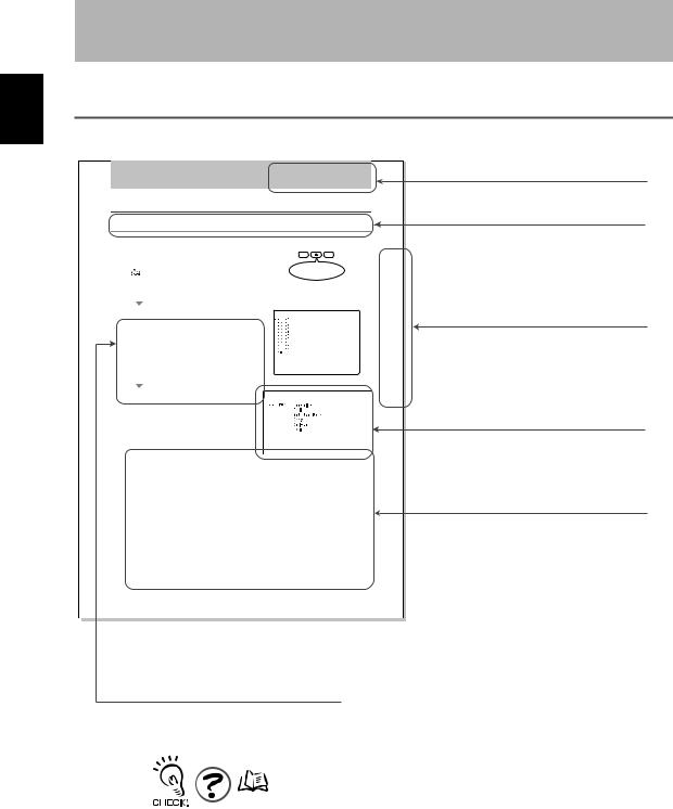
How to Use This Manual
Page Format
Section 2
Changing Reading Conditions
Setting Reading Conditions Manually
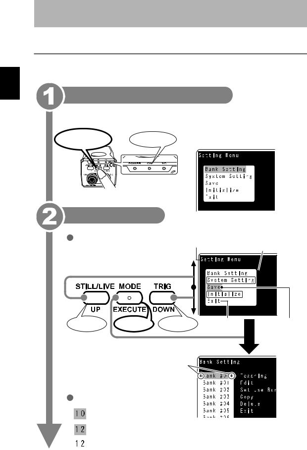
This section explains how to set reading conditions manually.
|
1. Switch to the setting mode. |
|
|
|
|
|
|
|
|
|
|
|
|
|
|
|
||||
|
|
|
|
|
|
|
STILL/LIVE MODE |
TRIG |
|
|
|
|
|
|
||||||
|
|
|
Hold down the center button for more than two seconds to |
|
|
|
|
|
|
|
|
|
|
|||||||
|
|
|
|
|
UP EXECUTE |
DOWN |
|
|
|
|
|
2Section |
||||||||
|
|
|
activate the setting mode. |
|
|
|
|
|
|
Hold down for more |
|
|
|
|
|
|||||
|
|
|
|
“Changing Settings” p.24 |
|
|
|
|
|
|
|
|
|
|
|
|
||||
|
|
|
|
|
|
|
|
|
|
than two seconds. |
|
|
|
|
|
|
||||
|
2. Select [Bank Setting] from [Setting Menu]. |
|
|
|
|
|
|
|
|
|
|
|
||||||||
|
|
|
|
|
|
|
|
|
|
|
|
|||||||||
|
|
|
|
|
|
|
|
|
|
|
Setting |
|||||||||
|
|
|
|
|
|
|
|
|
|
|
|
|
|
|
|
|
|
|
|
|
|
|
|
|
|
|
|
|
|
|
|
|
|
|
|
|
|
|
|||
|
|
|
|
|
|
|
|
|
|
|
|
|
|
|
|
|
|
|||
|
|
|
The [Bank Setting] screen will appear. |
|
|
|
|
|
|
|
|
|
|
|
|
|||||
|
3. From [Bank #00] to [Bank #09], select the |
|
|
|
|
|
|
|
|
|
|
|
Reading |
|||||||
|
|
|
|
|
|
|
|
|
|
|||||||||||
|
|
|
right area of the screen. |
|
|
|
|
|
|
|
|
|
|
|
|
|
|
Conditions |
||
|
|
|
bank to which you want to set reading |
|
|
|
|
|
|
|
|
|
|
|
|
|||||
|
|
|
condition. |
|
|
|
|
|
|
|
|
|
|
|
|
|
|
|
|
|
|
|
|
The contents of the selected bank are displayed in the |
|
|
|
|
|
|
|
|
|
|
|
|
|||||
|
|
|
|
|
|
|
|
|
|
|
|
|
|
|
|
|
|
|
|
Manually |
|
|
|
|
|
|
|
|
|
|
|
|
|
|
|
|
|
|
|
|
|
|
|
|
|
|
|
|
|
|
|
|
|
|
|
|
|
|
|
|||
|
|
|
|
|
|
|
|
|
|
|
|
|
|
|
|
|
|
|||
|
|
|
The edit menu will be displayed. |
|
|
|
|
|
|
|
|
|
|
|
|
|||||
|
|
|
|
|
|
|
|
|
|
|
|
|
|
|
|
|
|
|
|
|
|
|
|
|
|
|
|
|
|
|
|
|
|
|
|
|
|
|
|
|
|
|
|
|
|
|
|
|
|
|
|
|
|
|
|
|
|
|
|
|
|
|
|
|
|
Setting item |
Settings |
|
|
|
|
|
Details |
|
|
|
|
|
|
|
|||
|
|
|
Light Channel |
Select the light to be used. |
|
|
|
|
|
|
|
|
|
|
|
|||||
|
|
|
|
|
(For V400-F050) |
|
|
|
|
|
|
|
|
|
|
|
|
|
|
|
|
|
|
|
|
Right CH.* |
The light connected to the right light connector will be used. |
|
|
|
|
||||||||||
|
|
|
|
|
|
|
|
|
|
|
|
|||||||||
|
|
|
|
|
Left CH. |
The light connected to the |
left light connector will be used. |
|
|
|
|
|||||||||
|
|
|
|
|
|
|
|
|
|
|
|
|
|
|
|
|
|
|||
|
|
|
|
|
None |
No light will be used. |
|
|
|
|
|
|
|
|
|
|
|
|||
|
|
|
|
|
|
|
|
|
|
|
|
|
|
|
|
|
|
|
|
|
|
|
|
Code Type |
Set the code type. |
|
|
|
|
|
|
|
|
|
|
|
|
|
|
|
|
|
|
|
|
|
|
|
|
|
|
|
||||||||||
|
|
|
|
|
DataMatrix |
The code will be read as a DataMatrix type code. |
|
|
|
|
||||||||||
|
|
|
|
|
|
|
|
|
|
|
|
|
|
|||||||
|
|
|
|
|
QRCode |
The code will be read as a QRCode type code. |
|
|
|
|
|
|
|
|||||||
|
|
|
|
|
Auto* |
The code type will be identified automatically. |
|
|
|
|
|
|
|
|||||||
|
|
|
|
|
|
|
|
|
|
|
|
|
|
|
|
|
||||
|
|
|
Shape |
Select the code shape. |
|
|
|
|
|
|
|
|
|
|
|
|||||
|
|
|
|
|
This item is effective only when [DataMatrix] is selected for [Code Type]. |
|
|
|
|
|||||||||||
|
|
|
|
|
Square |
The code will be read as a square code. |
|
|
|
|
|
|
|
|||||||
|
|
|
|
|
|
|
|
|
|
|
|
|
|
|||||||
|
|
|
|
|
Rectangle |
The code will be read as a rectangular code. |
|
|
|
|
|
|
|
|||||||
|
|
|
|
|
|
|
|
|
|
|
||||||||||
|
|
|
|
|
Auto* |
The code shape will be identified automatically. |
|
|
|
|
||||||||||
|
|
|
|
|
|
|
|
|
|
|
|
|
|
|
|
|
|
|||
|
|
|
|
|
|
|
|
|
|
|
|
|
V400-F050/250/350 |
|
31 |
|||||
|
|
|
|
|
|
|
|
|
|
|
|
|
|
|||||||
|
|
|
|
|
|
|
|
|
|
|
|
|
|
User's Manual |
|
|||||
|
|
|
|
|
|
|
|
|
|
|
|
|
|
|
|
|
|
|
|
|
Section title
Outline
Index label
Provides the section number and subject matter. Can be used to immediately open the desired page.
Screen display
Describes the settings.
Procedure and additional explanations
Information useful during the operation and reference pages are provided here with special marks to indicate the kind of information being provided.
*This page does not actually exist in this manual.
8 |
|
V400-F050/250/350 |
|
||
|
User’s Manual |
|
|
|
|
Introduction
Visual Aids
Indicates points that are important in using product functions or in application procedures.
Indicates page numbers providing related information.
Indicates helpful information when a problem occurs and explanations of technical terms.
Aids Visual Introduction
V400-F050/250/350 |
9 |
User’s Manual |

Contents Introduction
Introduction
Contents
Introduction
|
Meanings of Signal Words |
4 |
|
|
|
|
Meanings of Alert Symbols |
4 |
|
|
|
|
Alert Statements in this Manual |
4 |
|
|
|
|
Regulations and Standards |
5 |
|
|
|
|
Precautions for Safe Use |
5 |
|
|
|
|
|
|
|
Precautions for Correct Use |
6 |
|
|
|
|
How to Use This Manual |
8 |
|
|
|
|
Visual Aids |
9 |
|
|
|
|
Contents |
10 |
|
|
|
|
|
|
Section 1 Studying the V400-F |
13 |
|
|
|
|
|
|
|
|
Features and Functions of V400-F |
14 |
|
|
|
|
Installing and Connecting the Code Reader |
18 |
|
|
|
|
|
|
|
Simple Teaching |
22 |
|
|
|
|
|
|
|
Changing Settings |
24 |
|
|
|
|
Reading Results |
26 |
|
|
|
Section 2 Changing Reading Conditions |
29 |
|
|
|
|
|
|
|
|
Setting Reading Conditions by Teaching |
30 |
|
|
|
|
Setting Reading Conditions Manually |
32 |
|
|
|
|
Selecting the Bank to be Used Normally |
37 |
|
|
|
|
Copying a Bank |
38 |
|
|
|
|
|
|
|
Deleting the Content of a Bank |
40 |
|
|
|
|
|
|
|
Setting the Retry Method |
41 |
|
|
|
|
|
|
10 |
|
V400-F050/250/350 |
|
||
|
User’s Manual |
|
|
|
|

|
|
Introduction |
|
|
|
Section 3 Setting RS-232C and Discrete I/O Communication Conditions |
43 |
|
|
|
|
|
|
|
|
Setting RS-232C Communication Conditions |
44 |
|
|
|
|
Setting Discrete I/O Communication Conditions |
48 |
|
|
|
|
|
|
Section 4 Other Settings |
51 |
|
|
|
|
|
|
|
|
Setting Screen Display |
52 |
|
|
|
|
Viewing the Images Read in the Past |
53 |
|
|
|
|
|
|
|
Saving/Initializing All the Settings |
56 |
|
|
|
|
Displaying the Version Information |
58 |
|
|
|
Section 5 Communicating with PC and Programmable Controller |
59 |
|
|
|
|
|
|
|
|
RS-232C Communication |
60 |
|
|
|
|
Discrete I/O Communication |
73 |
|
|
|
Section 6 Troubleshooting |
81 |
|
|
|
|
|
|
|
|
Error Codes and Corrective Actions |
82 |
|
|
|
|
|
|
|
Troubleshooting |
82 |
|
|
|
Appendix |
85 |
|
|
|
|
|
|
|
|
Lens and Lighting |
86 |
|
|
|
|
Line Speed and Reading Time/Exposure Time |
91 |
|
|
|
|
Maintenance |
93 |
|
|
|
|
Specifications and Dimensions |
94 |
|
|
|
|
|
|
|
ASCII Table |
99 |
|
|
|
|
Ladder Programming Example for Connecting to a PLC |
100 |
|
|
|
|
FCS Check Program Example (BASIC) |
104 |
|
|
|
|
Data Capacity Table |
106 |
|
|
|
|
Menu Hierarchy |
109 |
|
|
|
|
|
|
|
Revision History |
110 |
|
|
|
|
|
|
Contents Introduction
V400-F050/250/350 |
11 |
User’s Manual |

Contents Introduction
Introduction
MEMO
12 |
|
V400-F050/250/350 |
|
||
|
User’s Manual |
|
|
|
|

Section 1
Studying the V400-F
This section provides items, such as the V400-F is features, installation, connections and operation flow, with which the operator should be familiar to use the V400-F.
|
|
Features and Functions of V400-F |
14 |
|
|
||
|
|
|
|
|
|
Compact and Easy-to-Operate |
14 |
|
|
Advanced Functions |
16 |
|
|
Other Features |
17 |
|
|
Installing and Connecting the Code Reader |
18 |
|
|
||
|
|
|
|
|
|
Mounting the Main Unit |
18 |
|
|
Connecting Peripheral Devices |
20 |
|
|
Simple Teaching |
22 |
|
|
||
|
|
|
|
|
|
Changing Settings |
24 |
|
|
||
|
|
|
|
|
|
Reading Results |
26 |
|
|
||
|
|
|
|
|
|
Monitor Display |
26 |
|
|
RS-232C Communications Output |
28 |
F-V400 the Studying 1 Section
V400-F050/250/350 |
13 |
User’s Manual |
F-V400 of Functions and Features 1 Section
Section 1
Studying the V400-F
Features and Functions of V400-F
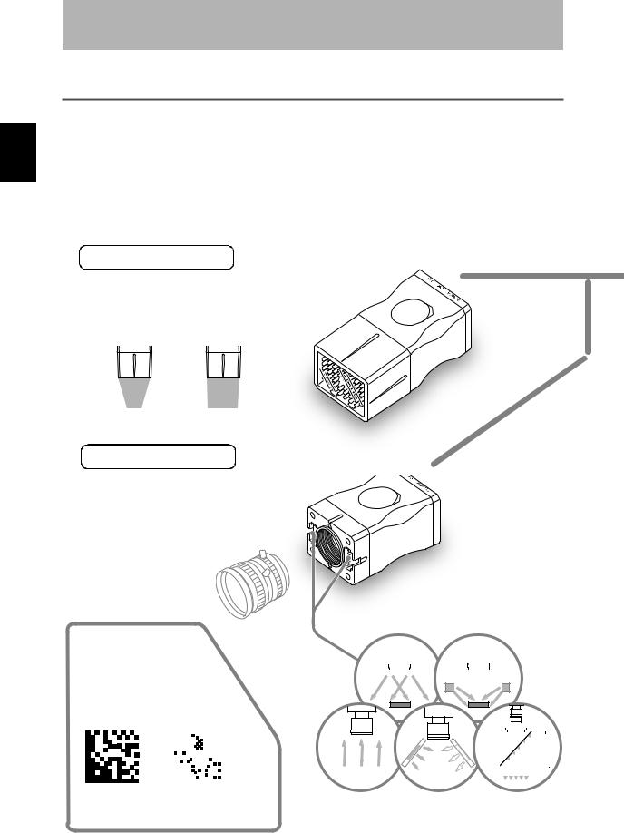
This fixed type 2D code reader provides advanced reading functions and is designed for easy operation by anyone. It reads 2D codes directly marked on boards and metal materials.
Two types of code reader are available: the V400-F250/350, whose lens and light are integrated into one compact body, and the V400-F050, to which a C-mount lens can be attached to enable use of various lights.
 Compact and Easy-to-Operate
Light/Lens Integrated Type V400-F250/350
 Light and Lens are Integrated
Eliminates troublesome lens mounting and light.
V400-F250 V400-F350
Narrow |
|
|
Wide |
|
light |
-field light |
-field |
||||
External size: 40 × 50 × 97 mm
C-mount Type |
V400-F050 |
|
 Allows Mounting of a C-mount Type Lens
 Provides Two Connectors that
Allow Direct Connection of Light
No power source is required for the light.
C-mount type lens (Recommended:
 p.89)
p.89)
External size: 40 × 50 × 75 mm
 Supports DataMatrix ECC200 (max. 64 × 64)
Readable codes
Direct ring light |
Low-angle ring light |
||||||||||||||
|
|
|
|
|
|
|
|
|
|
|
|
|
|
|
|
|
|
|
|
|
|
|
|
|
|
|
|
|
|
|
|
|
|
|
|
|
|
|
|
|
|
|
|
|
|
|
|
|
|
|
|
|
|
|
|
|
|
|
|
|
|
|
|
|
|
|
|
|
|
|
|
|
|
|
|
|
|
|
|
|
|
|
|
|
|
|
|
|
|
|
|
|
|
|
|
|
|
|
|
|
|
|
|
|
|
|
|
|
|
|
|
(Recommended:

 p.86)
p.86)
DataMatrix QRCode
|
|
|
|
|
|
|
|
|
|
|
|
|
|
|
|
|
|
|
|
|
|
|
|
|
|
|
|
|
|
|
|
|
|
|
|
|
|
|
|
|
|
|
|
|
|
|
|
|
|
|
|
|
|
|
|
|
|
|
|
|
|
|
|
|
|
|
|
|
|
|
|
|
|
|
|
|
|
|
|
|
|
|
|
|
|
|
|
|
|
|
|
|
|
|
|
|
|
|
|
|
|
|
|
|
|
|
|
|
|
|
|
|
|
|
|
|
|
|
|
|
|
|
|
|
|
|
|
|
|
|
|
|
|
|
|
|
|
|
|
|
|
|
|
|
|
|
|
|
|
|
|
|
|
|
|
• ECC200 |
• Model 1, 2 |
|
Back light |
Reflected light |
|
Coaxial light |
|||||||||||||||||||
10 × 10 to 64 × 64 |
21 × 21 to 57 × 57 |
|
|
||||||||||||||||||||||
|
|
|
|
|
|
|
|
|
|
|
|
|
|
|
|
|
|
|
|
||||||
8 × 18 to 16 × 48 |
(Version 1 to Version 10) |
|
|
|
|
|
|
|
|
|
|
|
|
|
|
|
|
|
|
|
|
||||
14 |
|
V400-F050/250/350 |
|
||
|
User’s Manual |
|
|
|
|

Section 1
Studying the V400-F
Checking Reading Results by Easy-to-See LEDs
 Easy Operations with 3 Buttons
POWER LED (green) |
OK LED (blue) |
NG LED (red) |
Lit when power is ON. |
Lights up when reading is successful. |
Lights up when |
|
|
reading has failed. |
Left button |
|
|
|
|
|
|
|
|
|
|
|
|
|
|
|
|
|
|
|
|
|
|
Right button |
|
Switches between still and real- |
|
|
|
|
|
|
|
|
|
|
|
|
|
|
|
|
|
|
|
|
|
|
|
|
|
|
|
|
|
|
|
|
|
|
|
|
|
|
|
|
|
|
|
|
|
|
Performs reading. |
|
|
time images. (* Monitor required) |
|
|
|
|
|
|
|
|
|
|
|
|
|
|
|
|
|
POWER |
OK |
NG |
|
|||
Adjusts brightness (hold down for |
|
|
|
|
|
|
|
|
|
|
|
|
|
|
|
|
|
|
|
|
|
|
“Simple Teaching” |
|
two seconds). (* Monitor required) |
|
|
|
|
|
|
|
|
|
|
|
|
|
STILL/LIVE MODE |
TRIG |
(Hold down for two seconds) |
||||||||
Center button |
|
|
|
|
|
|
|
|
|
|
|
|
|
|
|
|
|
|
UP |
EXECUTE |
DOWN |
Communication/power cable |
||
|
|
|
|
|
|
|
|
|
|
|
|
|
|
|
|
|
|
|
|
|
||||
----------- |
|
|
|
|
|
|
|
|
|
|
CN1 |
|
|
|
|
|
CN2 |
connector |
|
|||||
|
|
|
|
|
|
|
|
|
|
|
|
|
|
|
|
|
|
|||||||
Switches to setting mode |
|
|
|
|
|
|
|
|
|
|
|
|
|
|
|
|
|
|
c e |
|
|
|
Monitor cable connector |
|
(hold down for two seconds). |
|
|
|
|
|
|
|
|
|
|
|
|
|
|
|
o |
u |
r |
|
|
|
|
|
|
(* Monitor required) |
|
|
|
|
|
|
|
|
|
|
|
|
|
|
s |
|
|
|
|
|
|
|||
|
|
|
|
|
|
|
|
|
|
|
|
|
|
|
|
|
|
|
|
|
||||
|
|
|
|
|
|
|
|
|
|
|
|
|
e |
|
|
|
|
|
|
|
|
|||
|
|
|
|
|
|
|
|
|
|
|
|
|
|
|
|
|
|
Corporation |
MADE IN JAPAN |
|
|
|||
|
|
|
|
|
|
|
|
|
|
|
|
o |
w |
Omronr |
|
|
||||||||
|
|
|
|
|
|
|
|
|
|
e |
/ p |
|
|
|
|
|
|
|
|
|
|
|
||
|
|
|
|
|
|
|
|
|
ic |
|
|
|
|
|
|
|
|
|
|
|
|
|||
|
|
|
|
|
|
|
|
v |
|
|
|
|
|
|
|
|
|
|
|
|
|
|||
|
|
|
|
|
|
|
e |
|
|
|
|
|
|
|
|
|
) |
|
|
|
|
|||
|
|
|
|
|
|
d |
|
|
|
|
|
|
|
|
|
0 |
|
|
|
|
||||
|
|
|
|
|
t |
|
|
|
|
|
|
|
|
|
|
|
|
|
|
|||||
|
|
|
|
s |
|
|
|
|
|
|
|
|
|
|
|
|
One-Touch Reading by |
|
||||||
|
|
|
o |
|
|
|
|
|
|
|
|
|
|
|
|
|
|
|
||||||
|
|
h |
|
|
|
|
|
|
|
|
|
|
|
|
|
|
|
|
|
|||||
|
|
|
|
|
|
|
|
|
|
|
|
|
|
|
|
|
|
|
|
|||||
T |
o |
|
|
|
|
|
|
|
|
|
|
|
|
|
|
|
|
|
|
20) |
“Simple Teaching” |
.22) |
||
|
|
|
|
|
|
|
|
|
|
|
|
|
|
|
|
|
|
|
||||||
|
|
|
|
|
|
|
|
|
|
|
|
|
|
|
|
|
|
|
|
|||||
|
|
Teaching/reading can be executed |
|
|
and completed by just holding down |
|
r |
the right button for two seconds. |
|
o |
Reading can be started without |
|
n |
|
|
t |
|
|
i |
|
|
o |
monitor. |
Programmable controller |
m |
|
o |
Various Retry Functions |
|
|
T |
|
|
|
.41) |
|
|
Retry can be performed not only with |
Power |
|
different exposure time, but also with |
|
two or more reading conditions that |
|
supply |
|
|
|
are switched automatically. |
|
device |
|
|
PC |
|
|
Connecting to a Monitor
Allows Advanced Settings
POWER
SYNC
F-V400 of Functions and Features 1 Section
V400-F050/250/350 |
15 |
User’s Manual |
F-V400 of Functions and Features 1 Section
Section 1
Studying the V400-F
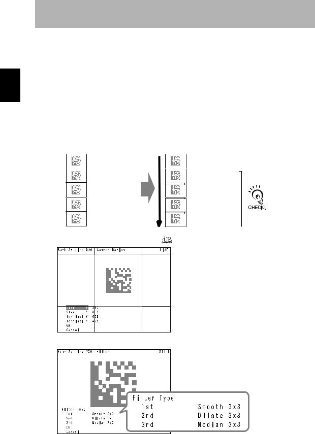
 Advanced Functions
 Retrying by switching to another bank automatically (
 p.41)
p.41)
Retry is performed by switching the reading condition (Bank) among the maximum five conditions.
Two condition switching methods are available: one which determines the order of the conditions to be used automatically according to the frequency of their use, and the other that switches them according to the registered order.
Combining with the retry settings that are made for each reading condition enables various retry settings.
[Automatically determining the order according to frequency of use]
 1st Bank
Successful retry count: 25
 2nd Bank
Successful retry count: 1
 3rd Bank
Successful retry count: 50
 4th Bank
Successful retry count: 15
 5th Bank
Successful retry count: 9
 Setting the reading region
 Previous reading was successful. Reading condition (example: 5th Bank)
 3rd Bank
Successful retry count: 50
1st Bank |
|
For the 2nd and |
Successful retry count: 25 |
|
|
|
subsequent |
|
4th Bank |
|
|
|
retries, the reading |
|
Successful retry count: 15 |
|
|
|
condition used for |
|
2nd Bank |
|
|
|
the 1st retry will be |
|
Successful retry count: 1 |
|
|
|
excluded. |
( |
p.33) |
Set the image region to be read.
This shortens the processing time.
 Setting a filter (
 p.34)
p.34)
Performing image processing before reading reduces possibility of reading error. Filtering can be performed in 3 steps.
• Smooth, Dilate/Erosion, Median
16 |
|
V400-F050/250/350 |
|
||
|
User’s Manual |
|
|
|
|
Section 1
Studying the V400-F
 Enables switching between two lights (V400-F050 only) (
 p.34)
p.34)
The light to be used can be switched between two lights according to the situation.
Combining this function with the auto bank switch retry function enables the code reader to handle partially reflecting work pieces.
 Other Features
Saves up to 10 reading conditions ( p.30)
p.30)
Saves up to 28 past read images ( p.53)
p.53)
This allows you to identify the errors that occurred, by checking the saved past images.
Supports NPN/PNP by simply exchanging the cable.
Allows direct power supply to the monitor.
Use of the monitor cable (V400-WM0) and LCD monitor (F150-M05L-2D) enables the V400-F to supply power to the monitor, making settings monitoring and maintenance easy.
Displays results in various ways ( p.26)
p.26)
Highlights the reading state. |
Displays analysis result of code quality numerically |
|||||||
Highlighting ( |
p.26) |
and graphically (bar). |
|
|||||
|
|
|
|
Code quality analysis display ( |
p.27) |
|||
|
|
|
|
|||||
|
|
|
|
|
|
|
|
|
|
|
|
|
|
|
|
|
|
|
|
|
|
|
|
|
|
|
|
|
|
|
|
|
|
|
|
Displays the RS-232C communication history.
Communication history display ( p.27)
p.27)
F-V400 of Functions and Features 1 Section
V400-F050/250/350 |
17 |
User’s Manual |
Reader Code the Connecting and Installing 1 Section
Section 1
Studying the V400-F
Installing and Connecting the Code Reader
.
 Mounting the Main Unit
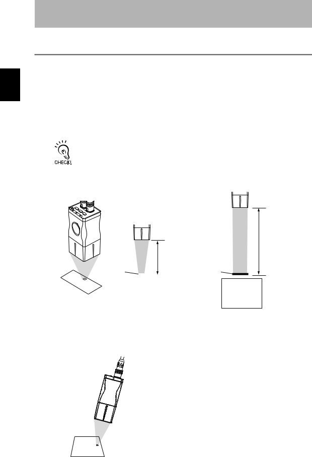
Mount the reader at a distance where the code image can be shot correctly. There are two mounting methods: “DIN track mounting” and “Base mounting”.
Field of Vision and Distance from the Code
• An accurate image will not be obtained if the installation distance is too long or too short. Always use the installation distance given below.
• The field of vision and installation distance of the V400-F050 vary with the lens to be used.  “Selecting a Lens” p.89
V400-F250 |
V400-F350 |
|
CN2 |
|
|
|
|
|
DOWN |
|
|
Corporation |
Omron |
|
TRIG |
EXECUTE |
|
|
|
NG |
MODE |
|
|
|
|
STILL/LIVE |
UP |
CN1 |
|
||
|
OK |
|
|
|
|
|
POWER |
|
|
|
|
Installation distance: 200 mm
Installation distance: 100 mm
Code |
|
|
|
Code |
|
|
|
|
|
|
|
|
|
|
|
|
|
Field of vision 14 × 18.5 mm
Field of vision 31 × 42 mm
Glossy Workpieces
Install the Main Unit at an angle so that regular reflective light is not included in the image.
Recommended Installation Angle
Model |
Recommended angle |
V400-F250 |
10° |
|
|
V400-F350 |
5° |
|
|
18 |
|
V400-F050/250/350 |
|
||
|
User’s Manual |
|
|
|
|
Section 1
Studying the V400-F
Base Mounting
Mount the reader with four M3 screws.
Mounting dimensions (Unit: mm)
2-M3
(Screw fitting length: 5 mm or less)
Mounting the Mount Seat
First mount the mount seat, then mount the reader to the seat with two M4 screws. The reader can also be mounted with one 1/4-20UNC screw.
Mounting dimensions
(Unit: mm)
2-M4
(Screw fitting length: 8 mm or less)
|
1/4-20 UNC |
|
(Screw fitting length: 8 mm or less) |
DIN Track Mounting |
|
1. Mount the mount seat to the |
2. Slide the seat into the DIN rail, and |
undersurface of the base of the |
then tighten the two screws at one |
reader with M3 screws (supplied |
edge of the rail using the hexagonal |
with the reader). |
wrench (supplied with the reader). |
Reader Code the Connecting and Installing 1 Section
V400-F050/250/350 |
19 |
User’s Manual |

Reader Code the Connecting and Installing 1 Section
Section 1
Studying the V400-F
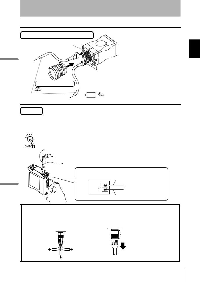
 Connecting Peripheral Devices
Connect peripheral devices to the reader.
Always turn OFF the reader before connecting or disconnecting a peripheral device's cable.
 Peripheral devices may be damaged if the cable is connected or disconnected with the power ON. The connector (CN2) for the monitor is capped when the reader is shipped. The cap must be left on
 those connectors that are not used to protect them from dust, dirt and static electricity.
Main
Align the marks.
Attach a ferrite core.
The ferrite core must be located at least 10 mm away from the
base of the connector.
Programmable controller |
or |
|
|
||
Communication/ |
V400-W23 (NPN type) |
|
power cable |
V400-W23P (PNP type) |
|
Power |
Blue |
|
supply |
|
|
device |
Brown |
|
Recommended: OMRON |
|
|
S8VS-03024 |
|
|
Programmable controller |
|
|
Discrete I/O
 Wiring method: p.73
Make sure that the connector is oriented correctly and not inserted at an angle. Secure the connector using the screws on both sides of the connector.
RS-232C connector (male)
RS-232C connector
Monitor
F150-M05L-2D
Align the
marks.
When plugging in a connector, push it with a
force of no more than
15 to 20 N.
Then, pull gently on the cable (approximately
10 N) to make sure the
connector is securely connected.
Monitor cable V400-WM0
+24 V |
0 V |
Brown |
Blue |
|
PC |
|
|
V400-W24 (NPN type) |
Communication/ |
||
V400-W24P (PNP type) |
power cable |
||
Brown |
|
|
|
Blue |
|
Power |
|
Recommended: OMRON |
supply |
||
device |
|||
S8VS-03024 |
|||
|
|||
|
PC |
|
|
RS-232C connector |
|
|
|
(female) |
|
|
|
|
Make sure that the |
||
|
connector is oriented |
||
|
correctly and not inserted |
||
|
at an angle. Secure the |
||
RS-232C connector |
connector using the |
||
screws on both sides of |
|||
the connector.
20 |
|
V400-F050/250/350 |
|
||
|
User’s Manual |
|
|
|
|
Section 1
Studying the V400-F
Lens and light (for V400-F050 only)
Left-side light cable connector
Right-side light cable connector
To the light
Align the projection on the light cable is connector with the slot on the connector of the reader.
C-mount type lens
|
Recommended lens: p.89 |
|
Light cable |
Light |
Recommended light: p.86 |
|
To the light |
|
Power
For V400-F050/250/350, a power supply device must be provided separately. Wire the power supply independently of other devices. In particular, keep the power supply wired separately from inductive loads.
Use a DC power supply with safety measures against high-voltage spikes (safety extra lowvoltage circuits on the secondary side). If UL recognition is required for the overall system, use a UL Class II DC power supply.
Use a power supply that meets the following requirements.
Output current |
1.2 A min. |
Power supply voltage |
24 VDC ±10% |
Recommended |
S8VS-03024 |
Connect the brown wire to the positive (+) side of the power supply and the blue wire to the negative (-) side.
(+) side Brown
(-) side Blue
Handling the Cable
After the connector is plugged in, do not apply a force of more than 30 N to the connector in the directions shown below.
Excessive force will damage the connector.
30 N max. |
30 N max. |
30 N max.
When disconnecting a cable, hold the part of the plug shown below and then pull it out straight.
Hold this part.
Reader Code the Connecting and Installing 1 Section
V400-F050/250/350 |
21 |
User’s Manual |
Teaching Simple 1 Section
Section 1
Studying the V400-F
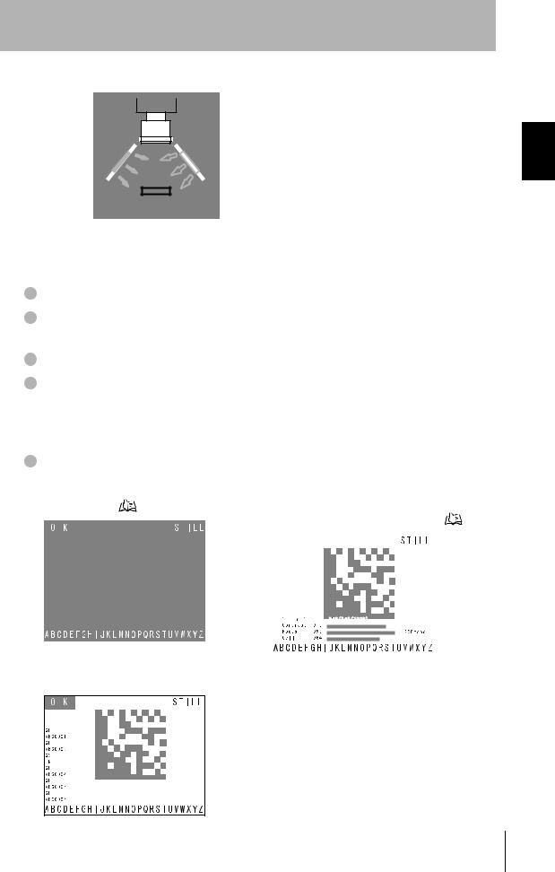
Simple Teaching
Use “Simple Teaching” to check whether codes on the work piece are readable.
“Simple Teaching” enables you to set necessary reading conditions automatically by simple operations.
To change reading conditions or set them in detail, use the setting mode.
Turning ON the power
Turn ON the power to the monitor. |
The POWER LED |
• When using F150-M05L-2D, make sure |
(green) will light up. |
that it is connected before turning ON the |
|
power to the power supply device. |
|
Turn ON the power to the power supply device. 

The POWER LED (green) will light up.
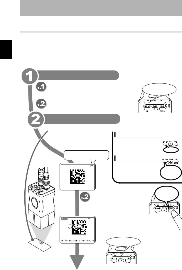
Performing teaching
 Capture the work piece.
Switch to the real-time image display mode, and adjust the position and brightness of the work piece while observing the image on the monitor.
[STILL]: Still image [LIVE]: Real-time image
Display switching
Press the left button to switch
from the still image to the real-
time image or vice versa.
Press
Brightness adjustment
Hold down the left button for more |
|
|
than two seconds, to display the |
Hold down for |
|
exposure time adjustment screen. |
||
more than two |
||
The brightness will be adjusted |
||
seconds. |
||
based on the exposure time. |
||
|
|
Hold down for |
Perform teaching. |
more than two |
seconds. |
Hold down the right button for more than two seconds, to perform “Simple Teaching”.
When teaching is completed successfully, the teaching and reading results will be displayed. Three indicators will light: Power (green), OK (blue), and NG (red). Select [OK] to save the results.
Indicators light:
Power (green), OK (blue),
NG (red).
22 |
|
V400-F050/250/350 |
|
||
|
User’s Manual |
|
|
|
|

Section 1
Studying the V400-F
• The teaching results will be overwritten, registered to [Bank #00], and saved.
• If [Cancel] is selected in the result display screen, the results will not be saved.
Exiting
Turn OFF the power to the power supply device and then to the monitor.
Teaching Simple 1 Section
V400-F050/250/350 |
23 |
User’s Manual |
Settings Changing 1 Section
Section 1
Studying the V400-F
Changing Settings
The setting mode allows you to make changes to reading conditions and system settings. This section explains operations for the setting mode.
Switch to the setting mode.
Hold down the center button for more than two seconds.
All the LEDs will light up and the [Setting Menu] appears.
Hold down for more |
All LEDs light up. |
|
than two seconds. |
||
|
Make settings
Basic operation for setting mode
Use the right and left buttons to select the desired item, and then press the center button to confirm the selection.
To close the current menu, select [Exit] and then press the center button.
Name of currently
selected menu Selectable menus are enclosed in a white frame.
Select an item. |
Confirm |
Select an item. Select [Exit] to |
|
|
close the menu. |
(Example) When [Bank Setting] is selected
Indicates that this reading condition is normally used.
* Only when [Bank Setting] is selected
Numerical value inputting method
Move the cursor to the desired item and press the center button.
Change the value using the right and left buttons.
Press the center button to confirm the setting.
The currently selected item is enclosed in a blue frame. (Cursor)
24 |
|
V400-F050/250/350 |
|
||
|
User’s Manual |
|
|
|
|
Section 1
Studying the V400-F
 Setting the reading conditions
Select [Bank Setting] from [Setting Menu].
 Other settings
Select [System Setting] from [Setting Menu].
 p.29
p.29
•Up to 10 reading conditions are available.
•When a reading condition is selected, its settings will be displayed in the right area of the screen.
•Select the desired reading condition from among the ten conditions, and set each condition item manually or by teaching.
•Reading conditions can be copied or deleted.
Reading condition [Bank #00] contains the contents of “Simple Teaching”.
[RS-232C] |
Set RS-232C communication related parameters such as |
p.44 |
|
baud rate and parity. |
|
|
|
|
[Data Format] |
Set data format setting for RS-232C communication. |
p.46 |
|
|
|
[Discrete I/O] |
Set discrete I/O related settings including trigger mode |
p.48 |
|
and busy input. |
|
|
|
|
[Display] |
Change the monitor display method. |
p.52 |
|
|
|
[Image Store] |
Select the methods for storing images and referring to |
p.53 |
|
stored images. |
|
|
|
|
[Bank Switching] |
Change the automatic bank switch retry setting. |
p.41 |
|
|
|
[Version Information] |
Displays the software version. |
p.58 |
|
|
|
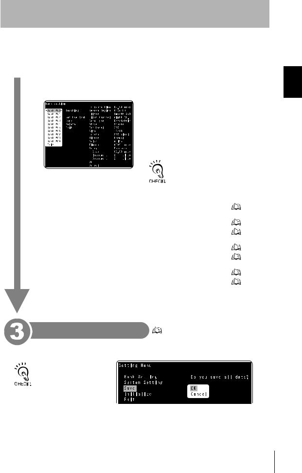
Saving the settings |
p.56 |
|
Settings Changing 1 Section
Select [Save] from [Setting Menu].
All the settings including reading conditions will be saved.
Before exiting, make sure to save the settings in the setting mode. If the settings are not saved, the reading conditions and other settings will be lost.
V400-F050/250/350 |
25 |
User’s Manual |
Results Reading 1 Section
Section 1
Studying the V400-F
Reading Results
This section explains details of the read results.
 Monitor Display
Explanation of reading results displayed on the monitor is given below.
There are four display methods: normal display, highlighting display, code quality analysis display and communication display.
The desired display method can be set in the setting mode.
 Display setting: p.52
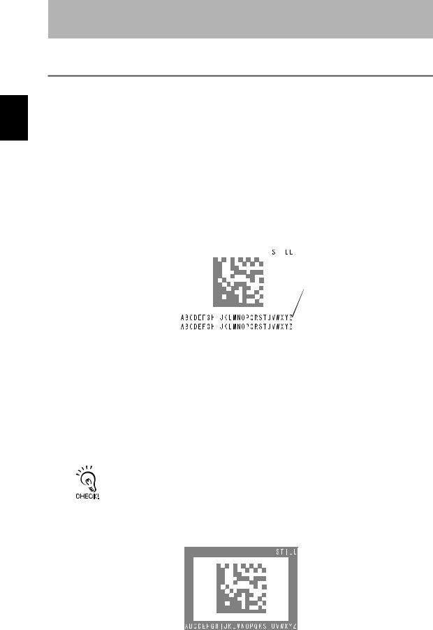
Normal Display
Normal screen
Reading status |
|
|
|
|
|
|
|
|
|
|
|
|
|
The reading status is |
|
|
|
|
|
|
displayed. |
|
|
|
|
|
|
OK (blue):Reading is |
|
|
|
|
Read data |
|
completed |
|
|
|
|
||
|
|
|
|
The read data is displayed. |
||
successfully. |
|
|
|
|
||
|
|
|
|
(Max. 208 characters = |
||
NG (red): Reading has |
|
|
|
|
||
|
|
|
|
8 lines × 26 characters) |
||
failed. |
|
|
|
|
||
|
|
|
|
|||
|
|
|
|
|
|
An error code is displayed in case of |
|
|
|
|
|
|
|
• Error code contents |
|
|
|
|
reading error. |
|
|
|
|
|
|||
|
|
|
|
|
||
Error code |
Action |
?E000 |
2D code cannot be found, possibly due to uneven background. Check the work piece |
|
surface and lighting condition. |
|
|
?E100 |
2D code cell cannot be recognized correctly. Check the marking and lighting conditions, |
|
and then perform teaching again. |
|
|
?E200 |
Reading was not completed within the specified period of time. Check the work piece and |
|
lighting condition, then perform teaching again. |
|
Increase the reading timeout value. |
|
|
If reading has failed, it may be possible that the cause can be identified by checking the read image.  p.53
p.53
Highlighting Display
The screen is enclosed in a frame whose color that indicates the reading status.
Reading status 


The reading status is displayed.
OK (blue):Reading is completed successfully.
NG (red): Reading has failed.
 Read data
The read data is displayed. (Max. 26 characters)
An error code is displayed in case of reading error.
26 |
|
V400-F050/250/350 |
|
||
|
User’s Manual |
|
|
|
|
Section 1
Studying the V400-F
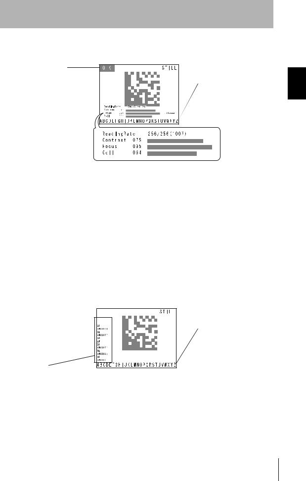
Code quality analysis display
This screen displays analysis result of code quality numerically and graphically (bar).
Reading status
The reading status is displayed. OK (blue):Reading is
completed successfully.
NG (red): Reading has failed.
Code quality analysis
The code quality analysis result is displayed numerically (0 to 100) and graphically (bar).
• Code quality analysis items
 Read data
The read data is displayed. (Max. 26 characters)
An error code is displayed in case of reading error.
Item |
Description |
Reading Rate |
Displays the rate of successful reading count to the total reading count. |
|
|
Contrast |
Evaluates the code is white/black contrast that varies with the lighting condition. |
|
The larger the difference between the white and black parts of the code, the larger the |
|
contrast. “1” will be displayed if the code is contrast is the minimum readable level. |
|
|
Focus |
Evaluates the focus level of the image. |
|
If the code is out of focus, it can no longer be recognized. The more the code is out of |
|
focus, the smaller the value displayed. |
|
|
Cell |
Evaluates the number of recognition fails for each cell in the finder pattern, timing pattern |
|
and data. |
|
The more cells in which recognition failure occurs and the more unstable the reading is, the |
|
smaller the value displayed. |
|
|
Communication Display
This screen displays the RS-232C communication history.
Reading status 


The reading status is
displayed. OK (blue):Reading is
completed successfully.
NG (red): Reading has failed.
Communication history
 Read data
The read data is displayed. (Max. 26 characters)
An error code is displayed in case of reading error.
The RS-232C communication history is indicated by yellow and green characters. Communication contents are displayed from the bottom to the top of the history display area. Yellow:Indicates that the content was input to the main body.
Green: Indicates that the content was output from the main body.
Results Reading 1 Section
V400-F050/250/350 |
27 |
User’s Manual |
Results Reading 1 Section
Section 1
Studying the V400-F
 RS-232C Communications Output
This section explains the reading results to be output via RS-232C communication.
When reading is successful
The read data is output in the following format.
Number of read data digits Code quality Read data
“Number of read data digits” and “Code quality” are output only if [Digit Data] and [Checker Data] are set to [ON] in the data format setting.
 p.46
p.46
When reading has failed
By factory default, an error code is output in the following format. However, it is possible to make a data format setting so that no error code will be output.
 Error code output setting: p.47
Header ?E000 Footer
 Error code: p.26, p.82
28 |
|
V400-F050/250/350 |
|
||
|
User’s Manual |
|
|
|
|
Loading...