


Cat.No. W318–E1–4
CompoBus/S
SRM1(-V2)
Master Control Units
OPERATION MANUAL
CompoBus/S
SRM1(-V2) Master Control Units
Operation Manual
Revised May 2000

Notice:
OMRON products are manufactured for use according to proper procedures by a qualified operator and only for the purposes described in this manual.
The following conventions are used to indicate and classify precautions in this manual. Always heed the information provided with them. Failure to heed precautions can result in injury to people or damage to property.
! DANGER Indicates an imminently hazardous situation which, if not avoided, will result in death or serious injury.
! WARNING Indicates a potentially hazardous situation which, if not avoided, could result in death or serious injury.
! Caution Indicates a potentially hazardous situation which, if not avoided, may result in minor or moderate injury, or property damage.
OMRON Product References
All OMRON products are capitalized in this manual. The word “Unit” is also capitalized when it refers to an OMRON product, regardless of whether or not it appears in the proper name of the product.
The abbreviation “Ch,” which appears in some displays and on some OMRON products, often means “word” and is abbreviated “Wd” in documentation in this sense.
The abbreviation “PC” means Programmable Controller and is not used as an abbreviation for anything else.
Visual Aids
The following headings appear in the left column of the manual to help you locate different types of information.
Note Indicates information of particular interest for efficient and convenient operation of the product.
1, 2, 3... 1. Indicates lists of one sort or another, such as procedures, checklists, etc.
OMRON, 1997
All rights reserved. No part of this publication may be reproduced, stored in a retrieval system, or transmitted, in any form, or by any means, mechanical, electronic, photocopying, recording, or otherwise, without the prior written permission of OMRON.
No patent liability is assumed with respect to the use of the information contained herein. Moreover, because OMRON is constantly striving to improve its high-quality products, the information contained in this manual is subject to change without notice. Every precaution has been taken in the preparation of this manual. Nevertheless, OMRON assumes no responsibility for errors or omissions. Neither is any liability assumed for damages resulting from the use of the information contained in this publication.
v
TABLE OF CONTENTS
PRECAUTIONS . . . . . . . . . . . . . . . . . . . . . . . . . . . . . . . . . |
xi |
|
1 Intended Audience . . . . . . . . . . . . . . . . . . . . . . . . . . . . . . . . . . . . . . . . . . . . . . . . . . . . . . . . . . . |
xii |
|
2 General Precautions . . . . . . . . . . . . . . . . . . . . . . . . . . . . . . . . . . . . . . . . . . . . . . . . . . . . . . . . . . |
xii |
|
3 Safety Precautions . . . . . . . . . . . . . . . . . . . . . . . . . . . . . . . . . . . . . . . . . . . . . . . . . . . . . . . . . . . |
xii |
|
4 Operating Environment Precautions . . . . . . . . . . . . . . . . . . . . . . . . . . . . . . . . . . . . . . . . . . . . . |
xiii |
|
5 Application Precautions . . . . . . . . . . . . . . . . . . . . . . . . . . . . . . . . . . . . . . . . . . . . . . . . . . . . . . |
xiii |
|
SECTION 1 |
|
|
Introduction . . . . . . . . . . . . . . . . . . . . . . . . . . . . . . . . . . . . |
1 |
|
1-1 SRM1 Features and Functions . . . . . . . . . . . . . . . . . . . . . . . . . . . . . . . . . . . . . . . . . . . . . . |
2 |
|
1-2 |
System Configuration . . . . . . . . . . . . . . . . . . . . . . . . . . . . . . . . . . . . . . . . . . . . . . . . . . . . . |
3 |
1-3 Procedures From System Design to Test Operation . . . . . . . . . . . . . . . . . . . . . . . . . . . . . |
7 |
|
1-4 I/O and Data Area Allocations . . . . . . . . . . . . . . . . . . . . . . . . . . . . . . . . . . . . . . . . . . . . . . |
8 |
|
SECTION 2 |
|
|
Specifications and Components . . . . . . . . . . . . . . . . . . . . |
11 |
|
2-1 |
Specifications . . . . . . . . . . . . . . . . . . . . . . . . . . . . . . . . . . . . . . . . . . . . . . . . . . . . . . . . . . . |
12 |
2-2 |
Unit Components . . . . . . . . . . . . . . . . . . . . . . . . . . . . . . . . . . . . . . . . . . . . . . . . . . . . . . . . |
15 |
SECTION 3 |
|
|
Installation and Wiring . . . . . . . . . . . . . . . . . . . . . . . . . . . |
17 |
|
3-1 |
System Design . . . . . . . . . . . . . . . . . . . . . . . . . . . . . . . . . . . . . . . . . . . . . . . . . . . . . . . . . . |
18 |
3-2 Selecting an Installation Site . . . . . . . . . . . . . . . . . . . . . . . . . . . . . . . . . . . . . . . . . . . . . . . |
19 |
|
3-3 |
Installing the SRM1 . . . . . . . . . . . . . . . . . . . . . . . . . . . . . . . . . . . . . . . . . . . . . . . . . . . . . . |
20 |
3-4 |
Wiring and Connections . . . . . . . . . . . . . . . . . . . . . . . . . . . . . . . . . . . . . . . . . . . . . . . . . . . |
21 |
3-5 |
One-to-one NT Link . . . . . . . . . . . . . . . . . . . . . . . . . . . . . . . . . . . . . . . . . . . . . . . . . . . . . . |
30 |
3-6 |
One-to-N NT Link . . . . . . . . . . . . . . . . . . . . . . . . . . . . . . . . . . . . . . . . . . . . . . . . . . . . . . . |
30 |
3-7 One-to-one PC Link Connections . . . . . . . . . . . . . . . . . . . . . . . . . . . . . . . . . . . . . . . . . . . |
31 |
|
SECTION 4 |
|
|
Using the Programming Console . . . . . . . . . . . . . . . . . . . |
33 |
|
4-1 |
Basic Operations . . . . . . . . . . . . . . . . . . . . . . . . . . . . . . . . . . . . . . . . . . . . . . . . . . . . . . . . |
34 |
4-2 |
Programming Console Operations . . . . . . . . . . . . . . . . . . . . . . . . . . . . . . . . . . . . . . . . . . . |
36 |
SECTION 5 |
|
|
Test Runs and Error Processing . . . . . . . . . . . . . . . . . . . . |
59 |
|
5-1 |
Startup Procedure . . . . . . . . . . . . . . . . . . . . . . . . . . . . . . . . . . . . . . . . . . . . . . . . . . . . . . . . |
60 |
5-2 |
Entering the Program . . . . . . . . . . . . . . . . . . . . . . . . . . . . . . . . . . . . . . . . . . . . . . . . . . . . . |
62 |
5-3 |
Test Run . . . . . . . . . . . . . . . . . . . . . . . . . . . . . . . . . . . . . . . . . . . . . . . . . . . . . . . . . . . . . . . |
71 |
5-4 |
Error Processing . . . . . . . . . . . . . . . . . . . . . . . . . . . . . . . . . . . . . . . . . . . . . . . . . . . . . . . . . |
72 |
5-5 Programming Console Operation Errors . . . . . . . . . . . . . . . . . . . . . . . . . . . . . . . . . . . . . . |
75 |
|
5-6 |
Programming Errors . . . . . . . . . . . . . . . . . . . . . . . . . . . . . . . . . . . . . . . . . . . . . . . . . . . . . . |
75 |
5-7 |
Troubleshooting Flowcharts . . . . . . . . . . . . . . . . . . . . . . . . . . . . . . . . . . . . . . . . . . . . . . . . |
77 |
SECTION 6 |
|
|
Expansion Memory Unit . . . . . . . . . . . . . . . . . . . . . . . . . . |
83 |
|
6-1 |
Overview . . . . . . . . . . . . . . . . . . . . . . . . . . . . . . . . . . . . . . . . . . . . . . . . . . . . . . . . . . . . . . |
84 |
6-2 |
Specifications and Nomenclature . . . . . . . . . . . . . . . . . . . . . . . . . . . . . . . . . . . . . . . . . . . |
85 |
6-3 |
Handling . . . . . . . . . . . . . . . . . . . . . . . . . . . . . . . . . . . . . . . . . . . . . . . . . . . . . . . . . . . . . . . |
86 |
vii
|
TABLE OF CONTENTS |
Appendices |
|
A Standard Models . . . . . . |
. . . . . . . . . . . . . . . . . . . . . . . . . . . . . . . . . . . . . . . . . . . . . . . . . . . . . 93 |
B External Dimensions . . . . |
. . . . . . . . . . . . . . . . . . . . . . . . . . . . . . . . . . . . . . . . . . . . . . . . . . . . 97 |
Glossary . . . . . . . . . . . . . . . . . . . . . . . . . . . . . . . . . . . . . . . 99
Index . . . . . . . . . . . . . . . . . . . . . . . . . . . . . . . . . . . . . . . . . . 115
Revision History . . . . . . . . . . . . . . . . . . . . . . . . . . . . . . . . . 119
viii

About this Manual:
The SRM1 is a special CompoBus/S controller that provides remote I/O with greatly reduced wiring. A distributed I/O system with up to 32 Slaves and 256 I/O points can be constructed. There are two manuals describing the setup and operation of the SRM1: The SRM1(-V2) Operation Manual (this manual) and the
CPM1/CPM1A/CPM2A/CPM2C/SRM1(-V2) Programming Manual (W353).
This manual describes the system configuration and installation of the SRM1 and provides a basic explanation of operating procedures for the Programming Consoles and introduces the capabilities of the SYSMAC Support Software (SSS). Read this manual first to acquaint yourself with the SRM1.
The CompoBus/S Operation Manual (W266) provides descriptions of the CompoBus/S system and Units.
The CPM1/CPM1A/CPM2A/CPM2C/SRM1(-V2) Programming Manual (W353) provides detailed descriptions of the SRM1’s programming functions. The SYSMAC Support Software (SSS) Operation Manuals: Basics (W247) and C-series PCs (W248) provide descriptions of SSS operations for the SRM1 and C-series PCs.
The SYSMAC-CPT Support Software Quick Start Guide (W332) and User Manual (W333) provide descriptions of ladder diagram operations in the Windows environment.
The WS02-CXPC1-E CX-Programmer User Manual (W361) and the CX-Server User Manual (W362) provide details of operations for the WS02-CXPC1-E CX-Programmer.
Please read this manual carefully and be sure you understand the information provide before attempting to install and operate the SRM1.
Section 1 describes the SRM1’s special features and functions and shows the possible system configurations.
Section 2 provides the technical specifications of the SRM1 and describes its main components.
Section 3 explains how to install and wire the SRM1. Be sure to follow the instructions contained here concerning the control panel, power supply, CompoBus/S transmissions, and RS-232C Port wiring.
Section 4 explains how to use the Programming Console. Be sure to read this section carefully if you are not already familiar with Programming Console operations.
Section 5 describes procedures for trial runs of SRM1 operation, self-diagnosis functions, and error processing to identify and correct the hardware and software errors that can occur during operation.
Section 6 describes how to use the CPM1-EMU01-V1 Expansion Memory Unit. Follow the handling precautions and procedures to properly use the Unit.
Appendix A provides a list of standard models.
Appendix B provides the external dimensions.
! WARNING Failure to read and understand the information provided in this manual may result in personal injury or death, damage to the product, or product failure. Please read each section in its entirety and be sure you understand the information provided in the section and related sections before attempting any of the procedures or operations given.
ix
PRECAUTIONS
This section provides general precautions for using the SRM1 and related devices.
The information contained in this section is important for the safe and reliable application of the SRM1. You must read this section and understand the information contained before attempting to set up or operate a CompoBus/S System.
1 Intended Audience . . . . . . . . . . . . . . . . . . . . . . . . . . . . . . . . . . . . . . . . . . . . . . . . . . . . . . . . . . . . |
xii |
|
2 |
General Precautions . . . . . . . . . . . . . . . . . . . . . . . . . . . . . . . . . . . . . . . . . . . . . . . . . . . . . . . . . . . |
xii |
3 |
Safety Precautions . . . . . . . . . . . . . . . . . . . . . . . . . . . . . . . . . . . . . . . . . . . . . . . . . . . . . . . . . . . . |
xii |
4 |
Operating Environment Precautions . . . . . . . . . . . . . . . . . . . . . . . . . . . . . . . . . . . . . . . . . . . . . . |
xiii |
5 |
Application Precautions . . . . . . . . . . . . . . . . . . . . . . . . . . . . . . . . . . . . . . . . . . . . . . . . . . . . . . . . |
xiii |
xi

Safety Precautions |
3 |
1 Intended Audience
This manual is intended for the following personnel, who must also have knowledge of electrical systems (an electrical engineer or the equivalent).
•Personnel in charge of installing FA systems.
•Personnel in charge of designing FA systems.
•Personnel in charge of managing FA systems and facilities.
2 General Precautions
The user must operate the product according to the performance specifications described in the operation manuals.
Before using the product under conditions which are not described in the manual or applying the product to nuclear control systems, railroad systems, aviation systems, vehicles, combustion systems, medical equipment, amusement machines, safety equipment, and other systems, machines, and equipment that may have a serious influence on lives and property if used improperly, consult your OMRON representative.
Make sure that the ratings and performance characteristics of the product are sufficient for the systems, machines, and equipment, and be sure to provide the systems, machines, and equipment with double safety mechanisms.
This manual provides information for programming and operating the OMRON SRM1. Be sure to read this manual before attempting to use the software and keep this manual close at hand for reference during operation.
! WARNING It is extremely important that an SRM1 and all CompoBus/S Units be used for the specified purpose and under the specified conditions, especially in applications that can directly or indirectly affect human life. You must consult with your OMRON representative before applying a CompoBus/S System to the abovementioned applications.
3Safety Precautions
!WARNING Never attempt to disassemble any Units while power is being supplied. Doing so
may result in serious electrical shock or electrocution.
! WARNING Never touch any of the terminals while power is being supplied. Doing so may result in serious electrical shock or electrocution.
! WARNING Provide safety measures in external circuits (i.e., not in the Programmable Controller), including the following items, in order to ensure safety in the system if an abnormality occurs due to malfunction of the PC or another external factor affecting the PC operation. Not doing so may result in serious accidents.
•Emergency stop circuits, interlock circuits, limit circuits, and similar safety measures must be provided in external control circuits.
•The PC will turn OFF all outputs when its self-diagnosis function detects any error or when a severe failure alarm (FALS) instruction is executed. As a countermeasure for such errors, external safety measures must be provided to ensure safety in the system.
•The PC outputs may remain ON or OFF due to deposition or burning of the output relays or destruction of the output transistors. As a countermeasure for such problems, external safety measures must be provided to ensure safety in the system.
xii

Application Precautions |
5 |
! WARNING When transferring programs to other nodes, or when making changes to I/O memory, confirm the safety of the destination node before transfer. Not doing so may result in injury.
! Caution Execute online edit only after confirming that no adverse effects will be caused by extending the cycle time. Otherwise, the input signals may not be readable.
4 Operating Environment Precautions
Do not operate the control system in the following places.
•Where the SRM1 is exposed to direct sunlight.
•Where the ambient temperature is below 0° C or over 55° C.
•Where the SRM1 may be affected by condensation due to radical temperature changes.
•Where the ambient humidity is below 10% or over 90%.
•Where there is any corrosive or inflammable gas.
•Where there is excessive dust, saline air, or metal powder.
•Where the SRM1 is affected by vibration or shock.
•Where any water, oil, or chemical may splash on the SRM1.
!Caution The operating environment of the CompoBus/S System can have a large effect
on the longevity and reliability of the system. Improper operating environments can lead to malfunction, failure, and other unforeseeable problems with the CompoBus/S System. Be sure that the operating environment is within the specified conditions at installation and remains within the specified conditions during the life of the system.
5 Application Precautions
Observe the following precautions when using the SRM1.
! WARNING Failure to abide by the following precautions could lead to serious or possibly fatal injury. Always heed these precautions.
•Always turn off the power supply to the SRM1 before attempting any of the following.
•Assembling any devices or racks.
•Connecting or disconnecting any cables or wiring.
!Caution Failure to abide by the following precautions could lead to faulty operation of the
SRM1 or the system or could damage the SRM1 or CompoBus/S Units. Always heed these precautions.
•Fail-safe measures must be taken by the customer to ensure safety in the event of incorrect, missing, or abnormal signals caused by broken signal lines, momentary power interruptions, or other causes.
•Construct a control circuit so that power supply for the I/O circuits does not come ON before power supply for the Unit. If power supply for the I/O circuits comes ON before power supply for the Unit, normal operation may be temporarily interrupted.
•If the operating mode is changed from RUN or MONITOR mode to PROGRAM mode, with the IOM Hold Bit ON, the output will hold the most recent status. In such a case, ensure that the external load does not exceed specifications. (If operation is stopped because of an operation error (including FALS instructions), the values in the internal memory of the CPU Unit will be saved, but the outputs will all turn OFF.)
xiii

Application Precautions |
5 |
•Use the Units only with the power supplies and voltages specified in the operation manuals.
•Take measures to stabilize the power supply to conform to the rated supply if it is not stable.
•Provide circuit breakers and other safety measures to provide protection against short-circuiting in external wiring.
•Install all Units according to instructions in the operation manuals.
•Do not install the Units in a place where they are subject to excessive noise in order to avoid any trouble or malfunction.
•Be sure that all the mounting screws, terminal screws, and cable connector screws are tightened to the torque specified in the relevant manuals. Incorrect tightening torque may result in malfunction.
•Double-check all the wiring before turning ON the power supply. Incorrect wiring may result in burning.
•Do not attempt to take any Units apart, to repair any Units, or to modify any Units in any way.
•Do not apply any impact to the Units.
•Use the cables specified in this manual and in reference manuals. Use crimp terminals when wiring the terminal block.
•Use a signal wire duct that is separate from the one used for high-tension lines or power lines.
•Be sure to confirm that the switch settings and wiring are correct before turning on the power supply.
•Check the user program for proper execution before actually running it on the Unit. Not checking the program may result in an unexpected operation.
•Confirm that the user programs run properly.
•Confirm that no adverse effect will occur in the system before attempting any of the following. Not doing so may result in an unexpected operation.
•Changing the operating mode of the PC.
•Force-setting/force-resetting any bit in memory.
•Changing the present value of any word or any set value in memory.
•Before touching the Unit, be sure to first touch a grounded metallic object in order to discharge any static build-up. Not doing so may result in malfunction or damage.
•Use, store, and transport the Units within the specifications provided in this manual.
•Resume operation only after transferring to the new SRM1 the contents of the DM and HR Areas required for resuming operation. Not doing so may result in an unexpected operation.
•Do not pull on the cables or bend the cables beyond their natural limit. Doing either of these may break the cables.
•Do not place objects on top of the cables. Doing so may break the cables.
•When replacing parts, be sure to confirm that the rating of a new part is correct. Not doing so may result in malfunction or burning.
•Be sure to observe local ordinances and laws when disposing the Units.
xiv
Application Precautions |
5 |
! Caution The following precautions are necessary to ensure the general safety of the system. Always heed these precautions.
•Provide double safety mechanisms to handle incorrect signals that can be generated by broken signal lines or momentary power interruptions.
•Provide external interlock circuits, limit circuits, and other safety circuits in addition to any provided within the SRM1 to ensure safety.
!Caution Be sure to clear the memory before turning on the power supply to the delivered
SRM1. The contents of the Data Memory (DM), Hold Relay (HR), and Counter (CNT) Areas in the CPU Unit may be cleared and the AR 1314 flag (which turns ON when the power interruption hold area is not held) may turn ON.
! Caution Apply the SRM1 to a system that is not influenced by any undefined data even if the data in the DM, HR, or CNT area is cleared when the SRM1 has been turned off for a period exceeding the data backup period of the internal lithium battery. If the AR 1414 flag is ON, the data will be held unless it is turned OFF by the I/O Monitor, instructions, etc.
The system can be stopped by designating DM 6604 in the PC Setup so that a memory error occurs when the power interruption hold area is not held (with AR 1314 ON)
•A lithium battery in the CPU Unit is used to back up the counter values and the contents of the DM area, and HR area. The deterioration of the lithium battery capacity depends on the ambient temperature. The standard service life is 12 years under an ambient temperature of 40_C when operating 8 hours a day.
If the power remains off for a period exceeding the data backup period, the contents of the Data Memory (DM), Hold Relay (HR), and Counter (CNT) Areas in the CPU Unit may be cleared and the AR 1314 flag (which turns ON when the power interruption hold area is not held) may turn ON.
If the contents of the CPU Unit’s program area are lost, the program stored in flash memory will be read to the CPU Unit’s program area when the SRM1 is started up because the contents in the read-only area (DM 6144 through DM 6599) and PC Setup (DM 6600 through DM 6655) will be written to flash memory.
•However, if the power is turned off without changing the mode even if changes are made in the read-only DM area (DM 6144 through DM 6599), or PC Setup (DM 6600 through DM 6655) using a peripheral device, the contents of changes will not be written to flash memory. Although the data in these areas is backed up by the lithium battery, contents of changes will disappear if the service life of the lithium battery expires. In this case, programs in the flash memory will be automatically read into the user program memory.
The changes can be saved by switching the SRM1 to RUN or MONITOR mode or turning off and restarting the SRM1 soon after the changes are made.
xv
SECTION 1
Introduction
This section describes the SRM1’s special features and functions and shows the possible system configurations.
1-1 |
SRM1 Features and Functions . . . . . . . . . . . . . . . . . . . . . . . . . . . . . . . . . . . . . . . . . . . . . . . |
2 |
|
|
1-1-1 |
Features . . . . . . . . . . . . . . . . . . . . . . . . . . . . . . . . . . . . . . . . . . . . . . . . . . . . . . . . . |
2 |
|
1-1-2 |
Functions . . . . . . . . . . . . . . . . . . . . . . . . . . . . . . . . . . . . . . . . . . . . . . . . . . . . . . . . |
2 |
1-2 |
System Configuration . . . . . . . . . . . . . . . . . . . . . . . . . . . . . . . . . . . . . . . . . . . . . . . . . . . . . . |
3 |
|
|
1-2-1 |
Basic Configuration . . . . . . . . . . . . . . . . . . . . . . . . . . . . . . . . . . . . . . . . . . . . . . . . |
3 |
|
1-2-2 |
SRM1 Models . . . . . . . . . . . . . . . . . . . . . . . . . . . . . . . . . . . . . . . . . . . . . . . . . . . . |
4 |
|
1-2-3 |
Peripheral Connections . . . . . . . . . . . . . . . . . . . . . . . . . . . . . . . . . . . . . . . . . . . . . |
5 |
1-3 |
Procedures From System Design to Test Operation . . . . . . . . . . . . . . . . . . . . . . . . . . . . . . . |
7 |
|
1-4 |
I/O and Data Area Allocations . . . . . . . . . . . . . . . . . . . . . . . . . . . . . . . . . . . . . . . . . . . . . . . |
8 |
|
|
1-4-1 |
I/O Allocations . . . . . . . . . . . . . . . . . . . . . . . . . . . . . . . . . . . . . . . . . . . . . . . . . . . . |
8 |
|
1-4-2 |
Data Area Allocation . . . . . . . . . . . . . . . . . . . . . . . . . . . . . . . . . . . . . . . . . . . . . . . |
9 |
1

SRM1 Features and Functions |
Section 1-1 |
1-1 SRM1 Features and Functions
1-1-1 Features
The SRM1 is a special CompoBus/S controller that provides remote I/O with greatly reduced wiring. The SRM1 has no built-in I/O terminals, but it can provide the same I/O control as earlier PCs through the Slaves (Slave Terminals) that are used for I/O.
A decentralized I/O system with up to 32 Slaves can be constructed. The system can have up to 256 I/O points and these I/O points are controlled with the CompoBus/S System’s high-speed response time of 1 ms max.
A very reliable and efficiently wired system can be constructed from special CompoBus/S components such as Analog Terminals (SRM1-C0j-V2 only), Remote Terminals, Sensor Terminals, Communications Cables, Connectors, and Terminators.
In SRM1-C0j-V2, the CompoBus/S system can be set to operate in long-dis- tance communications mode in addition to the previous high-speed communications mode. This allows a main line length of up to 500 m so that I/O devices can be controlled from some distance away. The SRM1-C0j-V2 can also process analog data as well as digital I/O.
The SRM1’s compact design allows for a smaller and thinner control panel.
The SRM1 is equipped with a program capacity of 4K words and a DM capacity of 2K words.
There are two SRM1(-V2) models available: the SRM1-C02-V2, which is equipped with an RS-232C port and communications functions, and the very cost-effective SRM1-C01-V2, which is not equipped with an RS-232C port.
1-1-2 Functions
Interval Timer Function |
The SRM1 is equipped with an interval timer which can be set from 0.5 ms to |
|
|
319,968 ms in units of 0.1 ms. The timer can be set to trigger a single interrupt |
|
|
(one-shot mode) or repeat scheduled interrupts (scheduled interrupt mode). |
|
|
(The interrupts pause execution of the main program while an interrupt program |
|
|
is executed.) |
|
Low-maintenance Design |
Memory can be backed up without a battery by using flash memory. |
|
Communications |
The SRM1 can communicate with PCs or other devices via Host Link, 1:1 NT |
|
|
Link, 1:N NT Link, 1:1 PC Link, or RS-232C communications. |
|
|
|
|
|
Port |
Applicable communications functions |
|
|
|
|
Peripheral Port |
Peripheral device connections, Host Link, and RS-232C |
|
|
communications |
|
|
|
|
RS-232C Port |
Host Link, 1:1 NT Link, 1:N NT Link, 1:1 PC Link, and no-protocol |
|
|
(RS-232C) communications |
Programming Using the
PT
Standard Peripheral Devices
Programming is possible through the PT (Programmable Terminal) screen using an OMRON PT that contains Programming Console functions. (This applies only to the SRM1-C02-V1 and SRM1-C02-V2.)
The SRM1 uses the same Programming Consoles, CX-Programmer, SYSMACCPT, and SYSMAC Support Software (SSS) as the Mini H-type, CQM1, CPM1/CPM1A, and CPM2A/CPM2C PCs.
2

System Configuration |
Section 1-2 |
Expansion Memory Unit The CPM1-EMU01-V1 Expansion Memory Unit is a program loader for smallsize or micro PCs. Using the CPM1-EMU01-V1, simple on-site transfer of user programs and data memory is possible with PCs.
Peripheral port
PERIPHERAL
RS-232C
1-2 System Configuration
1-2-1 Basic Configuration
Host device
Peripheral
device
CompoBus/S Communications Cable
Terminator
SRM1
Slave |
Slave |
Slave |
32 Slaves max.
3
|
System Configuration |
|
|
|
|
Section 1-2 |
||||
|
|
|
|
|
|
|
|
|
|
|
1-2-2 SRM1 Models |
|
|
|
|
|
|
||||
|
|
|
|
|
|
|
|
|
|
|
|
|
|
Model |
|
RS-232C port |
|
PT programming functions |
|||
|
|
|
|
|
|
|
|
|
|
|
|
|
|
SRM1-C01-V2 |
No |
|
No |
|
|
|
|
|
|
|
|
|
|
|
|
|
|
|
|
|
|
SRM1-C02-V2 |
Yes |
|
Yes |
|
|
|
|
|
|
The following table compares the functions in the SRM1(-V2) PCs with the func- |
||||||||
|
|
tions in earlier SRM1 PCs. |
|
|
|
|
|
|||
|
|
|
|
|
|
|
|
|
|
|
|
Function |
|
|
|
SRM1 models |
|
|
|
||
|
|
|
|
|
|
|
||||
|
|
|
SRM1-C0j-V2 |
|
SRM1-C0j-V1 |
SRM1-C0j |
||||
|
|
|
|
|
||||||
|
Data backup |
Backed up by a lithium battery with a minimum lifetime of 10 |
Capacitor backup |
|||||||
|
|
years at 25_C. |
|
|
|
|
|
|
||
|
|
|
|
|
||||||
|
Programming |
Programming can be performed through a Programming |
|
Programming can be performed |
||||||
|
Console functions |
Console connected to the peripheral port or an OMRON PT |
through a Programming Console |
|||||||
|
|
connected to the RS-232C port. |
|
|
|
|
connected to the peripheral port. |
|||
|
|
|
|
|
||||||
|
Data processing |
Bit data (ON/OFF for 16 bits) and 16-bit |
Bit data (ON/OFF status of bits) |
|||||||
|
|
analog data from Analog Units |
|
|
|
|
|
|
||
|
|
|
|
|||||||
|
Communications |
High-speed communications (previous |
High-speed communications mode (previous |
|||||||
|
|
mode) or long-distance communications |
mode) only. |
|
|
|
||||
|
|
mode |
|
|
|
|
|
|
||
|
|
|
|
|||||||
|
Connections with |
Host Link, no-protocol, 1:1 NT Link, 1:N NT |
Host Link, no-protocol, 1:1 NT Link, and 1:1 PC |
|||||||
|
host devices |
Link, and 1:1 PC Link communications |
Link communications |
|||||||
|
|
|
|
|||||||
|
Instructions |
The instructions in earlier SRM1 PCs plus |
Basic instructions: 14 |
|||||||
|
|
the following instructions: |
|
Special instructions: 77 (123 variations) |
||||||
|
|
NEG(––), PID(––), SCL(66), and ZCP(––) |
|
|
|
|
|
|||
Note The Analog Terminal can be used as a slave only with version-2 models. Incorrect data may be transferred if an Analog Terminal is used with the wrong model.
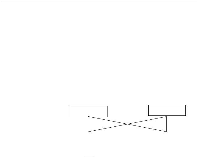
SRM1-C01-V2 |
SRM1-C02-V2 |
(No RS-232C port) |
(With RS-232C port) |
Peripheral port |
|
Peripheral port |
|
RS-232C port
4

System Configuration Section 1-2
1-2-3 |
Peripheral Connections |
|
|
|
|
The following peripherals can be connected to the SRM1(-V2) PCs. Refer to |
|||
|
Appendix A Standard Models for a complete list of connectable peripherals. |
|||
Slaves |
The following table shows the Slaves that can be connected. Refer to the Com- |
|||
|
poBus/S Operation Manual (W266) for more details. |
|||
|
|
|
|
|
|
|
Slave |
SRT2 Series |
SRT1 Series |
|
|
|
High-speed or long-distance |
High-speed |
|
|
|
communications |
communications only |
|
|
Remote Terminals |
SRT2-ID04 |
SRT1-ID04 |
|
|
(transistors) |
|
|
|
|
SRT2-ID04-1 |
SRT1-ID04-1 |
|
|
|
|
||
|
|
|
|
|
|
|
|
SRT2-ID08 |
SRT1-ID08 |
|
|
|
|
|
|
|
|
SRT2-ID08-1 |
SRT1-ID08-1 |
|
|
|
|
|
|
|
|
SRT2-ID16 |
SRT1-ID16 |
|
|
|
|
|
|
|
|
SRT2-ID16-1 |
SRT1-ID16-1 |
|
|
|
|
|
|
|
|
SRT2-ID16T |
None |
|
|
|
|
|
|
|
|
SRT2-ID16T-1 |
|
|
|
|
|
|
|
|
|
SRT2-OD04 |
SRT1-OD04 |
|
|
|
|
|
|
|
|
SRT2-OD04-1 |
SRT1-OD04-1 |
|
|
|
|
|
|
|
|
SRT2-OD08 |
SRT1-OD08 |
|
|
|
|
|
|
|
|
SRT2-OD08-1 |
SRT1-OD08-1 |
|
|
|
|
|
|
|
|
SRT2-OD16 |
SRT1-OD16 |
|
|
|
|
|
|
|
|
SRT2-OD16-1 |
SRT1-OD16-1 |
|
|
|
|
|
|
|
|
SRT2-OD16T |
None |
|
|
|
|
|
|
|
|
SRT2-OD16T-1 |
|
|
|
|
|
|
|
|
|
SRT2-MD16T |
|
|
|
|
|
|
|
|
|
SRT2-MD16T-1 |
|
|
|
|
|
|
|
|
Connector |
SRT2-VID08S |
None |
|
|
Terminals |
|
|
|
|
SRT2-VID08S-1 |
|
|
|
|
(transistors) |
|
|
|
|
|
|
|
|
|
SRT2-VID16ML |
|
|
|
|
|
|
|
|
|
|
|
|
|
|
|
SRT2-VID16ML-1 |
|
|
|
|
|
|
|
|
|
SRT2-VOD08S |
|
|
|
|
|
|
|
|
|
SRT2-VOD08S-1 |
|
|
|
|
|
|
|
|
|
SRT2-VOD16ML |
|
|
|
|
|
|
|
|
|
SRT2-VOD16ML-1 |
|
|
|
|
|
|
|
|
Remote Terminals |
SRT2-ROC08 |
SRT1-ROC08 |
|
|
(relays) |
|
|
|
|
SRT2-ROC16 |
SRT1-ROC16 |
|
|
|
|
||
|
|
|
|
|
|
|
Remote Terminals |
SRT2-ROF08 |
SRT1-ROF08 |
|
|
(power MOSFET) |
|
|
|
|
SRT2-ROF16 |
SRT1-ROF16 |
|
|
|
|
||
|
|
|
|
|
|
|
Remote Modules |
None |
SRT1-ROF08 |
|
|
|
|
|
|
|
|
|
SRT1-ROF16 |
|
|
|
|
|
|
|
Analog Input |
SRT2-AD04 |
None |
|
|
Terminal |
|
|
|
|
|
|
|
|
|
Analog Output |
SRT2-DA02 |
|
|
|
Terminal |
|
|
|
|
Sensor Amplifier |
SRT2-TID04S (See note 3.) |
SRT1-TID04S |
|
|
Terminals |
|
|
|
|
SRT2-TKD04S (See note 3.) |
SRT1-TKD04S |
|
|
|
|
||
|
|
|
|
|
|
|
Sensor Terminals |
SRT2-ID08S (See note 3.) |
SRT1-ID08S |
|
|
|
|
|
|
|
|
SRT2-OD08S (See note 3.) |
SRT1-OD08S |
|
|
|
|
|
|
|
|
SRT2-MD08S (See note 3.) |
SRT1-MD08S |
5
System Configuration |
Section 1-2 |
Compatible
Communications Modes
Slave |
SRT2 Series |
SRT1 Series |
|
High-speed or long-distance |
High-speed |
|
communications |
communications only |
Bit Chain Terminal |
None |
SRT1-B1T |
|
|
|
I/O Link Unit |
CPM1A-SRT21 |
None |
Note 1. SRT1-series Remote Terminals and Sensor Terminals can operate in highspeed communications mode only. Be sure to use SRT2-series Remote Terminals and Sensor Terminals when the SRM1-C0j-V2 is used in long-dis- tance communications mode.
2.The Analog I/O Terminals can be used with SRM1-C0j-V2 only.
3.To be marketed in the near future.
The long-distance communications mode can be used between SRM1-C0j-V2 Master Control Units and SRT2-series Slaves only, as shown in the following diagram. High-speed mode must be used if even one SRT1-series Slave is included in the CompoBus/S system.
Master Control Unit
SRM1-C0j-V2
Master Control Unit
SRM1-C0j,
SRM1-C0j-V1
|
|
|
|
|
|
|
|
|
|
|
SRT2-series Slave |
|
SRT2-series Slave |
|
|||
|
|
|
|
|
|
|
|
|
|
|
|
|
|
High-speed or long-distance communications mode |
|||
|
|
|
|
|
||||
|
|
|
|
|
High-speed communications mode only |
|||
Peripheral Devices |
The SRM1 can use a Programming Console or a personal computer running |
|||||||
|
CX-Programmer, SYSMAC Support Software (SSS), or SYSMAC-CPT as a Pe- |
|||||||
|
ripheral Device. |
|
|
|
||||
Programming Console
Programming Consoles are compact Peripheral Devices that support basic functions such as writing ladder programs and monitoring SRM1 operation. They are useful for onsite operations.
Refer to Section 4 Using a Programming Console for details on Programming
Console operations.
SYSMAC Support Software (SSS), SYSMAC-CPT, and CX-Programmer
In addition to the basic Programming Console operations, the CX-Programmer, SYSMAC-CPT, and SSS can be used to edit ladder programs offline, save programs to disk, and perform high-level monitoring; the CX-Programmer, SYS- MAC-CPT and SSS functions allow the user to design more efficient ladder programs. Refer to the manuals listed on the About this Manual page for details on using them.
SYSMAC Support Software (SSS)
When using the SSS, set the PC model to the “CQM1” and observe the following restrictions.
•Addresses will be checked according to the CQM1 address ranges, which are wider than the SRM1 address ranges. Be sure to use only the allowable addresses.
•The CQM1 has a larger memory than the SRM1 and the amount of memory available display will not be correct. Allow for the difference between capacities.
6

Procedures From System Design to Test Operation |
Section 1-3 |
Host Computers, PTs, and
PCs
•Instructions will be displayed that are not supported by the SRM1. Do not use these instructions.
CX-Programmer and SYSMAC-CPT
The following instructions cannot be programmed when using the CX-Program- mer or SYSMAC-CPT. Errors will occur if an attempt is made to transfer them from the PC to the computer: SCL(66)/@SCL(66), ZCP, NEG/@NEG, and PID.
An SRM1(-V2) can be connected an IBM PC/AT or compatible computer or OMRON PT through an RS-232C Adapter (CPM1-CIF01) mounted to the SRM1’s peripheral port. (Use Host Link mode when connecting a PT through an RS-232C Adapter.)
The RS-232C port on an SRM1-C02-V2 can be used to connect directly to an IBM PC/AT or compatible computer, OMRON PT, or PC (C200HX/HG/HE, C200HS, CQM1, CPM1, CPM1A, CPM2A, or CPM2C). (Use Host Link mode or NT Link mode when connecting a PT directly.)
1-3 Procedures From System Design to Test Operation
The procedures from system design to test operation are explained in the sections of this manual as follows and in the CPM1/CPM1A/CPM2A/CPM2C/ SRM1(-V2) Programming Manual (W353):
1, 2, 3... 1. System Design
Refer to 3-1 System Design.
2.Installation
Refer to 3-3 Installing the SRM1.
3.Wiring
Refer to 3-4 Wiring and Connections.
4.Creating the Ladder Program
Refer to the relevant sections in the CPM1/CPM1A/CPM2A/CPM2C/ SRM1(-V2) Programming Manual (W353) and the applicable PC manual.
5.Inputting the Program
Refer to Section 4 Using the Programming Console, Section 5 Test Runs and Error Processing, CX-Programmer Users Manual (W346), SYSMAC Support Software (SSS) Operation Manuals (W247 and W248), and SYS- MAC-CPT Support Software Quick Start Guide (W332) and User Manual
(W333).
6.Test Operation
Refer to 5-1-2 SRM1 Test Run Procedure.
7

I/O and Data Area Allocations |
Section 1-4 |
1-4 I/O and Data Area Allocations
1-4-1 I/O Allocations
The input bits of SRM1 words 000 to 007, and the output bits of words 010 to 017, are allocated to the CompoBus/S Slave. These allocations are shown in the following table.
I/O |
Word address |
|
Bits |
|
|
|
|
|
|
|
|
15 to 08 |
|
07 to 00 |
|
|
|
|
|
Inputs |
000 |
IN1 |
|
IN0 |
|
|
|
|
|
|
001 |
IN3 |
|
IN2 |
|
|
|
|
|
|
002 |
IN5 |
|
IN4 |
|
|
|
|
|
|
003 |
IN7 |
|
IN6 |
|
|
|
|
|
|
004 |
IN9 |
|
IN8 |
|
|
|
|
|
|
005 |
IN11 |
|
IN10 |
|
|
|
|
|
|
006 |
IN13 |
|
IN12 |
|
|
|
|
|
|
007 |
IN15 |
|
IN14 |
|
|
|
|
|
Outputs |
010 |
OUT1 |
|
OUT0 |
|
|
|
|
|
|
011 |
OUT3 |
|
OUT2 |
|
|
|
|
|
|
012 |
OUT5 |
|
OUT4 |
|
|
|
|
|
|
013 |
OUT7 |
|
OUT6 |
|
|
|
|
|
|
014 |
OUT9 |
|
OUT8 |
|
|
|
|
|
|
015 |
OUT11 |
|
OUT10 |
|
|
|
|
|
|
016 |
OUT13 |
|
OUT12 |
|
|
|
|
|
|
017 |
OUT15 |
|
OUT14 |
IN0 to IN15 are Input Slave node numbers, and OUT0 to OUT15 are Output
Slave node numbers.
If the maximum number of CompoBus/S devices is set to 16, then IN8 to IN15 and OUT8 to OUT15 can be used as work bits.
Words IR 008, IR 009, IR 018, and IR 019 can be used as work words.
The bits for two node number are allocated to 16-point Slaves so that all bits are in the same word. If an even node address is set, the node address that is set and the next node address following it will be used. For example, if node address 6 is set for a 16-point Output Slave, bits for node addresses OUT6 and OUT7 will be used. If an odd node address is set, the node address that is set and the previous node address will be used. For example, if node address 3 is set for a 16-point Output Slave, bits for node addresses OUT2 and OUT3 will be used.
All of the bits for one node address are allocated to a 4-point Slave. If an even numbered node address is set, bits 00 to 03 are used and bits 04 to 07 are not used. If an odd numbered node address is set, bits 8 to 11 are used and bits 12 to 15 are not used.
8

I/O and Data Area Allocations |
Section 1-4 |
Analog Terminals are allocated from 16 to 64 bits per Terminals as shown in the following table. If an allocation is not completely within the input or output area, communications will not be possible and the COMM indicator will not be lit.
I/O bits allocated |
Node |
Node addresses used |
Address |
|
address |
|
setting range |
|
setting |
|
|
|
|
|
|
64 bits |
Even |
Set address to set address + 7 |
0 to 9 |
(SRT2-AD04, 4 analog inputs) |
|
|
|
Odd |
Set address – 1 to set address + 6 |
|
|
|
|
||
|
|
|
|
48 bits |
Even |
Set address to set address + 5 |
0 to 11 |
(SRT2-AD04, 3 analog inputs) |
|
|
|
Odd |
Set address – 1 to set address + 4 |
|
|
|
|
||
|
|
|
|
32 bits |
Even |
Set address to set address + 3 |
0 to 13 |
(SRT2-AD04, 2 analog inputs) |
|
|
|
Odd |
Set address – 1 to set address + 2 |
|
|
(SRT2-DA02, 2 analog outputs) |
|
||
|
|
|
|
16 bits |
Even |
Set address to set address + 1 |
0 to 15 |
(SRT2-AD04, 1 analog input) |
|
|
|
Odd |
Set address – 1 to set address |
|
|
(SRT2-DA02, 1 analog output) |
|
||
|
|
|
|
Examples
If node address 3 is set for the SRT2-DA02 and 2 analog outputs are used, 32 bits are allocated from OUT2 to OUT5.
If node address 10 is set for the SRT2-AD04 and 4 analog inputs are used, the allocated area would exceed the output area available for allocation and communications would not be possible.
1-4-2 Data Area Allocation
The relationships between the data areas and words that can be used by the
SRM1 are shown in the following table. For details, refer to the CPM1/CPM1A/
CPM2A/CPM2C/SRM1(-V2) Programming Manual (W353).
Name |
Number of words or bits |
Word addresses |
|
|
|
Input bits |
8 words |
IR 000 to IR 007 |
|
|
|
Output bits |
8 words |
IR 010 to IR 017 |
|
|
|
Work bits |
44 words |
IR 008 and IR 009, |
|
(See note 1.) |
IR 018 and IR 019, |
|
|
IR 200 to IR 239 |
|
|
|
SR area |
16 words |
IR 240 to IR 255 |
|
|
|
HR area |
20 words |
HR 00 to HR 19 |
|
|
|
AR area |
16 words |
AR 10 to AR 15 |
|
|
(See note 2.) |
|
|
|
LR area |
16 words |
LR 00 to LR 15 |
|
|
|
DM area (Read/Write) |
2,022 words |
DM 0000 to DM 2021 |
|
|
|
DM area (Read Only) |
456 words |
DM 6144 to DM 6599 |
|
|
|
DM area (PC Setup) |
56 words |
DM 6600 to DM 6655 |
|
|
|
TR area |
8 bits |
TR 0 to TR 7 |
|
|
|
TIM/CNT area |
128 bits |
TIM/CNT 000 to 127 |
Note 1. When the CompoBus/S system is used in 128-bit mode, IR 004 to IR 007 and IR 014 to IR 017 can be used as work words.
2. AR 04 to AR 07 are used for Slave status.
9
SECTION 2
Specifications and Components
This section provides the technical specifications of the SRM1(-V2) and describes its main components.
2-1 |
Specifications . . . . . . . . . . . . . . . . . . . . . . . . . . . . . . . . . . . . . . . . . . . . . . . . . . . . . . . . . . . . |
12 |
|
|
2-1-1 |
General Specifications . . . . . . . . . . . . . . . . . . . . . . . . . . . . . . . . . . . . . . . . . . . . . . |
12 |
|
2-1-2 |
Characteristics . . . . . . . . . . . . . . . . . . . . . . . . . . . . . . . . . . . . . . . . . . . . . . . . . . . . |
13 |
|
2-1-3 |
CompoBus/S Communications Specifications . . . . . . . . . . . . . . . . . . . . . . . . . . . |
14 |
2-2 |
Unit Components . . . . . . . . . . . . . . . . . . . . . . . . . . . . . . . . . . . . . . . . . . . . . . . . . . . . . . . . . |
15 |
|
11

Specifications Section 2-1
2-1 |
Specifications |
|
2-1-1 |
General Specifications |
|
|
|
|
|
Item |
SRM1-C01/C02-V2 |
|
|
|
Supply voltage |
24 VDC |
|
|
|
|
Allowable supply voltage |
20.4 to 26.4 VDC |
|
|
|
|
Power consumption |
3.5 W max. |
|
|
|
|
Inrush current |
5.0 A max. (pulse width: 15 ms max.) |
|
|
|
|
Noise immunity |
Conforms to IEC61000-4-4; 2 kV (power lines) |
|
|
|
|
Vibration resistance |
10 to 57 Hz, 0.075-mm amplitude, 57 to 150 Hz, acceleration: 9.8 m/s2 in X, Y, and |
|
|
|
Z directions for 80 minutes each |
|
|
(Time coefficient; 8 minutes × coefficient factor 10 = total time 80 minutes) |
Shock resistance |
147 m/s2 three times each in X, Y, and Z directions |
|
Ambient temperature |
Operating: 0° C to 55° C |
|
|
|
Storage: –20° C to 75° C |
Absolute humidity |
10% to 90% (with no condensation) |
|
|
|
|
Atmosphere |
Must be free from corrosive gas. |
|
|
|
|
Terminal screw size |
M3 |
|
|
|
|
Power interrupt time |
DC type: 2 ms min. |
|
|
|
|
Weight |
|
150 g max. |
12

Specifications Section 2-1
2-1-2 Characteristics
Item |
|
SRM1-C01/C02-V2 |
|
|
|
Control method |
Stored program method |
|
|
|
|
I/O control method |
Cyclic scan method |
|
|
|
|
Programming language |
Ladder diagram |
|
|
|
|
Instruction length |
1 step per instruction, 1 to 5 words per instruction |
|
|
|
|
Types of instructions |
Basic instructions: |
14 |
|
Special instructions: |
81 instructions, 125 variations |
|
|
|
Execution time |
Basic instructions: |
0.97 s (LD instruction) |
|
Special instructions: |
9.1 s (MOV instruction) |
Program capacity |
4,096 words |
|
|
|
|
Maximum number of I/O points |
256 points |
|
|
|
|
Input bits |
00000 to 00715 (Words not used as input words can be used as work words.) |
|
|
|
|
Output bits |
01000 to 01715 (Bits not used as output bits can be used as work bits.) |
|
|
|
|
Work bits |
704 bits: 00800 to 00915 (Words IR 008 and IR 009) |
|
|
01800 to 01915 (Words IR 018 and IR 019) |
|
|
20000 to 23915 (Words IR 200 to IR 239) |
|
|
|
|
Special bits (SR area) |
248 bits: 24000 to 25507 (Words IR 240 to IR 255) |
|
|
|
|
Temporary bits (TR area) |
8 bits (TR0 to TR7) |
|
|
|
|
Holding bits (HR area) |
320 bits: HR 0000 to HR 1915 (Words HR 00 to HR 19) |
|
|
|
|
Auxiliary bits (AR area) |
256 bits: AR 0000 to AR 1515 (Words AR 00 to AR 15) |
|
|
|
|
Link bits (LR area) |
256 bits: LR 0000 to LR 1515 (Words LR 00 to LR 15) |
|
|
|
|
Timers/Counters |
128 timers/counters (TIM/CNT 000 to TIM/CNT 127) |
|
|
100-ms timers: TIM 000 to TIM 127 |
|
|
10-ms timers (high-speed counter): TIM 000 to TIM 003 |
|
|
Decrementing counters and reversible counters |
|
|
(Note: TIMH(15) will not time reliably if the cycle time is over 10 ms and timer |
|
|
numbers TIM 004 to TIM 127 are used.) |
|
|
|
|
Data memory |
Read/Write: 2,022 words (DM 0000 to DM 2021) |
|
|
Read-only: 512 words (DM 6144 to DM 6655) |
|
Interval timer interrupts |
One-shot mode/Scheduled interrupt mode, one bit (0.5 to 319,968 ms) |
|
|
|
|
Memory protection |
HR, AR, and DM area contents; and counter values maintained during power |
|
|
interruptions. |
|
|
|
|
Memory backup |
Flash memory: |
|
|
The program and read-only DM area are backed up without a battery. |
|
|
Lithium battery backup: |
|
|
The read/write DM area, HR area, AR area, and counter values are backed up by |
|
|
the lithium battery whose service life extends over ten years under an ambient |
|
|
temperature of 25_C. |
|
|
(Note: The lifetime of the lithium battery capacity depends on the ambient |
|
|
temperature. Refer to the descriptions on the next page.) |
|
|
|
|
Self-diagnostic functions |
CPU Unit failure (watchdog timer), memory check, communications errors, setting |
|
|
errors |
|
|
|
|
Program checks |
No END instruction, programming errors (continuously checked during operation) |
|
|
|
|
Peripheral port |
One point; tool connection, Host Link, no protocol |
|
|
|
|
RS-232C Port |
One point (SRM1-C02-V2 only); Host Link, 1:1 NT Link, 1:N NT Link, 1:1 PC Link, |
|
|
no protocol |
|
13

Specifications |
Section 2-1 |
Backup Time vs. Temperature A lithium battery in the CPU Unit is used to back up the contents in the user program area, the READ/WRITE area in the Data Memory (DM), Hold Relay (HR), the Auxiliary Memory Relay (AR), and in the data area of the Counter (CNT). The deterioration of the lithium battery capacity depends on the ambient temperature. The standard service life is 12 years under an ambient temperature of 40_C when operating 8 hours a day.
If the power supply is interrupted after the lithium battery capacity has deteriorated, the contents in the user program area, the READ/WRITE area in the Data Memory (DM), Hold Relay (HR), Auxiliary Memory Relay (AR), and in the data area of the Counter (CNT) may be lost. Even if the contents of the CPU Unit’s program area are lost, however, the user program and DM read-only contents (including the one in the PC Setup area) stored in flash memory will be read to the CPU Unit’s user program area when the SRM1 is next started up.
2-1-3 CompoBus/S Communications Specifications
|
Item |
Specifications |
|
|
|
|
|
Communications method |
CompoBus special protocol |
||
|
|
|
|
Transmission method |
Multi-drop, T-branch |
||
|
|
|
|
Baud rate |
|
High-speed |
750 kbps |
|
|
communications |
|
|
|
mode |
|
|
|
|
|
|
|
Long-distance |
93.75 kbps |
|
|
communications |
|
|
|
mode |
|
|
|
|
|
Modulation method |
Baseband method |
||
|
|
|
|
Code method |
|
|
Manchester coding method |
|
|
|
|
Maximum number of connectible |
32: 16 IN and 16 OUT |
||
terminals |
|
|
|
|
|
|
|
|
|
|
16: 8 IN and 8 OUT |
|
|
|
|
Number of points per frame |
256 (128 IN and 128 OUT), when maximum number of connectible terminals |
||
|
|
|
is 32. |
|
|
|
128 (64 IN and 64 OUT), when maximum number of connectible terminals is |
|
|
|
16. |
|
|
|
|
Communications |
|
High-speed |
0.8 ms, when maximum number of terminals is set to 32. |
cycle time |
|
communications |
|
|
0.5 ms, when maximum number of terminals is set to 16. |
||
|
|
mode |
|
|
|
|
|
|
|
Long-distance |
6.0 ms, when maximum number of terminals is set to 32. |
|
|
communications |
|
|
|
4.0 ms, when maximum number of terminals is set to 16. |
|
|
|
mode |
|
|
|
|
|
Communications function |
Cyclic transfer only (no message communications) |
||
|
|
||
Error control checks |
Manchester code check, frame length check, parity check, two-transfer |
||
|
|
|
comparison |
|
|
|
|
Communications |
|
High-speed |
Main line length: 100 m max. |
distance |
|
communications |
Branch line length: 3 m max. |
|
|
mode |
Total branch line length: 50 m max. |
|
|
|
|
|
|
Long-distance |
Main line length: 500 m max. |
|
|
communications |
Branch line length: 6 m max. |
|
|
mode |
Total branch line length: 120 m max. |
|
|
|
|
Cable |
|
Vinyl-clad VCTF |
Two 0.75 mm2 conductors (2 signal wires) |
|
|
JIS C 3306 |
|
|
|
|
|
|
|
Flat cable |
Four 0.75 mm2 conductors (2 signal wires and 2 power supply wires) |
14
Unit Components |
Section 2-2 |
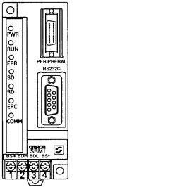
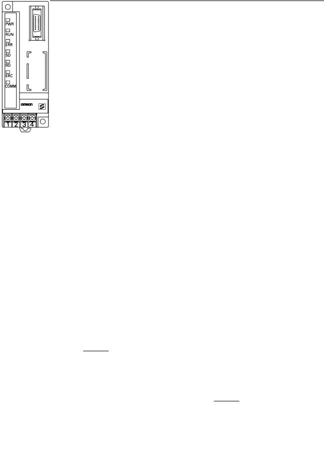
2-2 Unit Components
SRM1-C01-V2
4. CPU Unit status indicators |
2. Peripheral port |
|
|
|
Connector cover |
5.CompoBus/S communications status indicators
6.Peripheral/RS-232C port communications status indicators
1. Terminal block
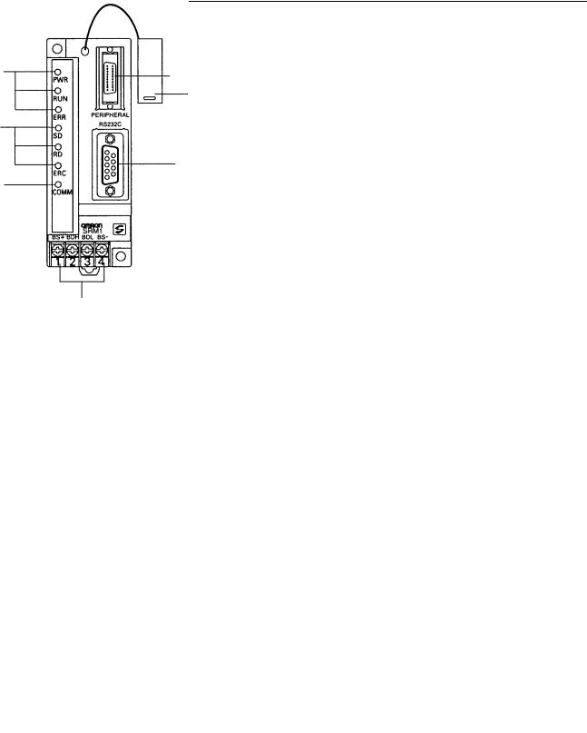
SRM1-C02-V2
4. CPU Unit status indicators |
2. Peripheral port |
|
|
|
Connector cover |
5. CompoBus/S communications status indicators |
|
|
3. RS-232C Port |
6. Peripheral/RS-232C Port communications status indicators |
|
|
|
1. Terminal block |
1) Terminal Block |
These terminals connect the power supply (24 V) and the CompoBus/S trans- |
|
|
|
mission path. For details regarding power supply wiring, refer to 3-4-2 Power |
|
|
Supply Wiring. |
2) |
Peripheral Port |
The Peripheral Port connects the programming tool or an RS-232C or RS-422 |
|
|
adapter. Be sure to use the correct cable. |
3) |
RS-232C Port |
The RS-232C Port connects to an RS-232C interface such as a personal com- |
|
|
puter or an OMRON PT. For details, refer to 3-4-4 RS-232C Port Wiring. |
15

Unit Components |
|
|
Section 2-2 |
|
4, 5, 6) Indicators |
There are three types of LED indicators: CPU Unit status indicators, CompoBus/ |
|||
|
S communications status indicators, and peripheral/RS-232C Port communica- |
|||
|
tions status indicators. These indicate the status of various Units, as shown in |
|||
|
the following table. |
|
|
|
|
|
|
|
|
|
Indicator |
Display |
Status |
|
|
|
|
|
|
|
PWR (Green) |
ON |
Power is being supplied. |
|
|
|
|
|
|
|
|
OFF |
Power is not being supplied. |
|
|
|
|
|
|
|
RUN (Green) |
ON |
In RUN mode or MONITOR mode |
|
|
|
|
|
|
|
|
OFF |
In PROGRAM mode or fatal error has occurred. |
|
|
|
|
|
|
|
ERR (Red) |
ON |
Fatal error has occurred. |
|
|
|
|
|
|
|
|
Flashing |
Non-fatal error has occurred. |
|
|
|
|
|
|
|
|
OFF |
Normal operation |
|
|
|
|
|
|
|
SD (Yellow) |
ON |
CompoBus/S data is being sent. |
|
|
|
|
|
|
|
|
OFF |
Data is not being sent. |
|
|
|
|
|
|
|
RD (Yellow) |
ON |
CompoBus/S data is being received. |
|
|
|
|
|
|
|
|
OFF |
Data is not being received. |
|
|
|
|
|
|
|
ERC (Red) |
ON |
A CompoBus/S communications error has |
|
|
|
|
occurred. |
|
|
|
|
|
|
|
|
OFF |
Normal operation |
|
|
|
|
|
|
|
COMM (Yellow) |
Flashing |
Data is being sent or received at the Peripheral |
|
|
|
|
Port or RS-232C Port. |
|
|
|
OFF |
Data is not being sent or received. |
|
16
SECTION 3
Installation and Wiring
This section explains how to install and wire the SRM1(-V2). Be sure to follow the instructions contained here concerning the control panel, power supply, CompoBus/S transmissions, and RS-232C Port wiring. For details regarding the wiring of CompoBus/S Terminal transmission paths and I/O, refer to the CompoBus/S Operation Manual (W266).
3-1 |
System Design . . . . . . . . . . . . . . . . . . . . . . . . . . . . . . . . . . . . . . . . . . . . . . . . . . . . . . . . . . . |
18 |
|
|
3-1-1 |
Power Supply Wiring . . . . . . . . . . . . . . . . . . . . . . . . . . . . . . . . . . . . . . . . . . . . . . . |
18 |
|
3-1-2 Interlock and Limit Circuits . . . . . . . . . . . . . . . . . . . . . . . . . . . . . . . . . . . . . . . . . . |
18 |
|
|
3-1-3 |
Power Supply Sequence . . . . . . . . . . . . . . . . . . . . . . . . . . . . . . . . . . . . . . . . . . . . . |
18 |
3-2 Selecting an Installation Site . . . . . . . . . . . . . . . . . . . . . . . . . . . . . . . . . . . . . . . . . . . . . . . . |
19 |
||
|
3-2-1 |
Installation Site Conditions . . . . . . . . . . . . . . . . . . . . . . . . . . . . . . . . . . . . . . . . . . |
19 |
|
3-2-2 |
Panel/Cabinet Installation . . . . . . . . . . . . . . . . . . . . . . . . . . . . . . . . . . . . . . . . . . . |
19 |
3-3 |
Installing the SRM1 . . . . . . . . . . . . . . . . . . . . . . . . . . . . . . . . . . . . . . . . . . . . . . . . . . . . . . . |
20 |
|
|
3-3-1 |
Surface Installation . . . . . . . . . . . . . . . . . . . . . . . . . . . . . . . . . . . . . . . . . . . . . . . . |
20 |
|
3-3-2 |
DIN Track Installation . . . . . . . . . . . . . . . . . . . . . . . . . . . . . . . . . . . . . . . . . . . . . . |
20 |
3-4 |
Wiring and Connections . . . . . . . . . . . . . . . . . . . . . . . . . . . . . . . . . . . . . . . . . . . . . . . . . . . . |
21 |
|
|
3-4-1 General Precautions for Wiring . . . . . . . . . . . . . . . . . . . . . . . . . . . . . . . . . . . . . . . |
21 |
|
|
3-4-2 |
Power Supply Wiring . . . . . . . . . . . . . . . . . . . . . . . . . . . . . . . . . . . . . . . . . . . . . . . |
23 |
|
3-4-3 CompoBus/S Transmission Line Wiring . . . . . . . . . . . . . . . . . . . . . . . . . . . . . . . . |
23 |
|
|
3-4-4 |
RS-232C Port Wiring . . . . . . . . . . . . . . . . . . . . . . . . . . . . . . . . . . . . . . . . . . . . . . . |
24 |
|
3-4-5 |
Host Link Connections . . . . . . . . . . . . . . . . . . . . . . . . . . . . . . . . . . . . . . . . . . . . . |
26 |
3-5 |
One-to-one NT Link . . . . . . . . . . . . . . . . . . . . . . . . . . . . . . . . . . . . . . . . . . . . . . . . . . . . . . . |
30 |
|
3-6 |
One-to-N NT Link . . . . . . . . . . . . . . . . . . . . . . . . . . . . . . . . . . . . . . . . . . . . . . . . . . . . . . . . |
30 |
|
3-7 One-to-one PC Link Connections . . . . . . . . . . . . . . . . . . . . . . . . . . . . . . . . . . . . . . . . . . . . |
31 |
||
|
3-7-1 |
Basics . . . . . . . . . . . . . . . . . . . . . . . . . . . . . . . . . . . . . . . . . . . . . . . . . . . . . . . . . . . |
31 |
|
3-7-2 |
Restrictions . . . . . . . . . . . . . . . . . . . . . . . . . . . . . . . . . . . . . . . . . . . . . . . . . . . . . . |
32 |
|
3-7-3 |
Cable Connections . . . . . . . . . . . . . . . . . . . . . . . . . . . . . . . . . . . . . . . . . . . . . . . . . |
32 |
|
3-7-4 |
PC Setup Settings . . . . . . . . . . . . . . . . . . . . . . . . . . . . . . . . . . . . . . . . . . . . . . . . . . |
32 |
17
System Design |
Section 3-1 |
3-1 System Design
Take the points covered in this section into consideration when designing the system.
3-1-1 Power Supply Wiring
Separate the power supply wiring from the control system, SRM1 system, and
DC I/O system wiring.
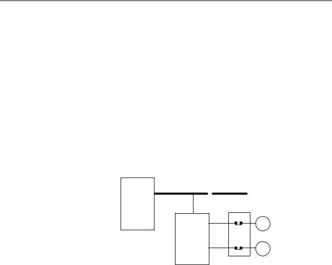
3-1-2 Interlock and Limit Circuits
Construct an external interlock circuit if SRM1 outputs are used to perform reciprocal operations such as controlling the forward and reverse operation of a motor or if incorrect SRM1 operation could cause accidents or mechanical damage. Also, construct an external limit circuit to prevent run-away movement in operations such as position control.
The following diagram shows an example of an interlock circuit.
CompoBus/S transmission path
SRM1
Interlock Circuit
01005 MC2
MC1 Motor forward
Slave
01006 MC1
MC2 Motor reverse
In the interlock circuit above, MC1 and MC2 cannot be ON at the same time even if SRM1 outputs 01005 and 01006 are both ON at the same time (an incorrect operation).
3-1-3 Power Supply Sequence
Time Up to the Start of Operation
The time from when the power supply is turned on to when the operation starts varies depending on the operation conditions such as power supply voltage, configuration, ambient temperature, etc. The minimum time is approximately 500 ms and the maximum is approximately 1.1 s.
Momentary Power Failure Detection
A momentary power failure (i.e., a voltage drop to less than 85% of the rated voltage) lasting less than 2 ms is not detected and the SRM1 continues to operate.
A momentary power failure lasting longer than 2 ms may cause the SRM1 to stop operation. If this occurs, operation will be automatically resumed when the rated voltage again rises above 85%.
Note The SRM1 may repeat stop/start operations if the supply voltage of less than 85% of the rated value gradually goes up or down. If this affects the equipment, etc., provide a protection circuit which shuts off the output if the supply voltage is not above the rated value.
The output status of Slaves when the SRM1 is stopped can be set on the Slave side either to have the ON/OFF status directly prior to the stop retained or to have all outputs turned OFF.
18

Selecting an Installation Site |
Section 3-2 |
3-2 Selecting an Installation Site
The SRM1 is resistant to harsh conditions and highly reliable, but installing it in a favorable site will maximize its reliability and operating lifetime.
3-2-1 Installation Site Conditions
Avoid installing the SRM1 in a site with any of the following conditions.
• Where the SRM1 is exposed to direct sunlight.
• Where the ambient temperature is below 0° C or over 55° C.
•Where the SRM1 may be affected by condensation due to radical temperature changes.
•Where the ambient humidity is below 10% or over 90%.
•Where there is any corrosive or inflammable gas.
•Where there is excessive dust, saline air, or metal powder.
•Where the SRM1 is affected by vibration or shock.
•Where any water, oil, or chemical may splash on the SRM1.
|
Be sure that the conditions at the installation site conform to the SRM1’s general |
|
|
specifications. Refer to 2-1-1 General Specifications for details. |
|
3-2-2 Panel/Cabinet Installation |
||
|
Consider PC operation, maintenance, and surrounding conditions when instal- |
|
|
ling the SRM1 in a panel or cabinet. |
|
Overheating |
The operating temperature range for the SRM1 is 0_C to 55_C. Be sure that |
|
|
there is adequate ventilation for cooling. |
|
|
• |
Allow enough space for air circulation. |
|
• |
Do not install the SRM1 above equipment that generates a large amount of |
|
|
heat, such as heaters, transformers, or large resistors. |
|
• |
Install a cooling fan or system when the ambient temperature exceeds 55_C. |
|
|
Control panel |
|
|
Fan |
|
|
SRM1 |
|
|
Air vent |
Electrical Noise |
Power lines and high-voltage equipment can cause electrical noise in the PC. |
|
|
• |
Do not install the SRM1 in a panel or cabinet with high-voltage equipment. |
|
• |
Allow at least 200 mm between the SRM1 and nearby power lines. |
200 mm min. |
|
|
Power lines |
|
|
||
|
|
|
|
|
SRM1 |
||
|
200 mm min. |
||
19
Installing the SRM1 |
|
Section 3-3 |
|
Accessibility |
Ensure that the SRM1 can be accessed for normal operation and maintenance. |
||
|
• |
Provide a clear path to the SRM1 for operation and maintenance. High-voltage |
|
|
|
equipment or power lines could be dangerous if they are in the way during rou- |
|
|
|
tine operations. |
|
|
• |
The SRM1 will be easiest to access if the panel or cabinet is installed about 3 to |
|
|
|
5 feet off of the floor. |
|
3-3 Installing the SRM1
The SRM1 can be installed on a horizontal surface or on a DIN track.
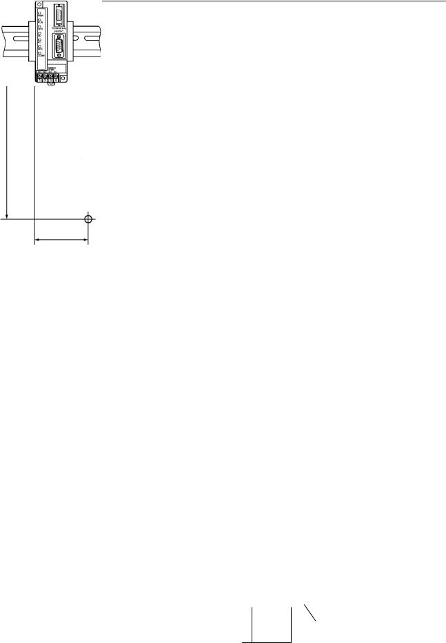
3-3-1 Surface Installation
Use the following pattern when installing an SRM1 on a horizontal surface.
Two M4 or two 4.2 dia.
100
(Unit: mm, with tolerance of ± 0.2 mm)
30
3-3-2 DIN Track Installation
The SRM1 can be installed on a 35-mm DIN track.
DIN Track
PFP-100N (1 m)
PFP-50N (50 cm)
End Plates
(PFP-M)
20
 Loading...