


SP10
Cat. No. W197-E1-2B
SYSMAC mini
SP10/SP16/SP20
Programmable Controller
SYSMAC mini Programmable Controllers
SP10/SP16/SP20
Operation Manual
Revised September 1997

Notice:
OMRON products are manufactured for use according to proper procedures by a qualified operator
and only for the purposes described in this manual.
The following conventions are used to indicate and classify precautions in this manual. Always heed
the information provided with them. Failure to heed precautions can result in injury to people or damage to the product.
DANGER Indicates information that, if not heeded, is likely to result in loss of life or serious injury.
!
WARNING Indicates information that, if not heeded, could possibly result in loss of life or serious injury .
!
Caution Indicates information that, if not heeded, could result in relatively serious or minor injury, dam-
!
age to the product, or faulty operation.
OMRON Product References
All OMRON products are capitalized in this manual. The word “Unit” is also capitalized when it refers
to an OMRON product, regardless of whether or not it appears in the proper name of the product.
The abbreviation “Ch,” which appears in some displays and on some OMRON products, often means
“word” and is abbreviated “Wd” in documentation in this sense.
The abbreviation “PC” means Programmable Controller and is not used as an abbreviation for anything else.
Visual Aids
The following headings appear in the left column of the manual to help you locate different types of
information.
OMRON, 1991
All rights reserved. No part of this publication may be reproduced, stored in a retrieval system, or transmitted, in any
form, or by any means, mechanical, electronic, photocopying, recording, or otherwise, without the prior written permission of OMRON.
No patent liability is assumed with respect to the use of the information contained herein. Moreover, because OMRON is
constantly striving to improve its high–quality products, the information contained in this manual is subject to change
without notice. Every precaution has been taken in the preparation of this manual. Nevertheless, OMRON assumes no
responsibility for errors or omissions. Neither is any liability assumed for damages resulting from the use of the information contained in this publication.
Note Indicates information of particular interest for efficient and convenient operation
of the product.
1, 2, 3...
1. Indicates lists of one sort or another, such as procedures, checklists, etc.
ii

About this Manual:
This manual describes the installation and operation of the SYSMAC mini Programmable Controllers
and includes the sections described below. The SYSMAC mini PCs include the SP10, SP16, and the
SP20 and are called SP-series PCs in this manual. Please read this manual completely and be sure
you understand the information provide before attempting to install and operation any of the SP-series PCs.
Section 1 Introduction
gramming. It also provides an overview of the process of programming and operating a PC and
explains basic terminology used with OMRON PCs. Descriptions of the features of the SP-series PCs
and Units that comprise SP-series systems are also provided.
Section 2 Installation
dimensions of all components are also presented.
Section 3 Programming
five subsections provide enough information to enable you to write, input, and execute a basic ladderdiagram program. The remainder of this section provides more advanced programming information,
3–7
with
Section 4 Operation
Console, such as monitoring, data modification, and Memory Card operations.
Section 5 Troubleshooting
also necessary when debugging a program.
The appendices provide tables of standard OMRON products available for the SP-series PCs, specifi-
cations, reference tables of instructions and Programming Console operations, and error and arithmetic flag operation. Also provided are several programming and data area assignment sheets that can
be copied out of the manual and used in developing programs.
describing individually each instruction in the SP-series instruction set.
explains the background and some of the terms used in ladder-diagram pro-
provides details on the installation environment and the wiring of the PC. The
describes information necessary for programming SP-series PCs. The first
provides further information on operating SP-series PCs via the Programming
provides information on error indications. Information in this section is
!
WARNING Failure to read and understand the information provided in this manual may result in personal
injury or death, damage to the product, or product failure. Please read each section in its
entirety and be sure you understand the information provided in the section and related
sections before attempting any of the procedures or operations given.
iii

TABLE OF CONTENTS
PRECAUTIONS ix . . . . . . . . . . . . . . . . . . . . . . . . . . . . . . . . . . . . . . . . . . . . . . . .
1 Intended Audience x . . . . . . . . . . . . . . . . . . . . . . . . . . . . . . . . . . . . . . . . . . . . . . . .
2 General Precautions x . . . . . . . . . . . . . . . . . . . . . . . . . . . . . . . . . . . . . . . . . . . . . . .
3 Safety Precautions x . . . . . . . . . . . . . . . . . . . . . . . . . . . . . . . . . . . . . . . . . . . . . . . .
4 Operating Environment Precautions x . . . . . . . . . . . . . . . . . . . . . . . . . . . . . . . . . . .
5 Application Precautions xi . . . . . . . . . . . . . . . . . . . . . . . . . . . . . . . . . . . . . . . . . . . .
SECTION 1 – Introduction 1 . . . . . . . . . . . . . . . . . . . . . . . . . . . . . . . . . . . . . . .
1-1 Features 2 . . . . . . . . . . . . . . . . . . . . . . . . . . . . . . . . . . . . . . . . . . . . . . . . . . . . . . . . .
1-2 PC Basics 2 . . . . . . . . . . . . . . . . . . . . . . . . . . . . . . . . . . . . . . . . . . . . . . . . . . . . . . .
1-2-1 PC Terminology 3 . . . . . . . . . . . . . . . . . . . . . . . . . . . . . . . . . . . . . . . . . .
1-2-2 Overview of PC Operation 4 . . . . . . . . . . . . . . . . . . . . . . . . . . . . . . . . .
1-3 Units 5 . . . . . . . . . . . . . . . . . . . . . . . . . . . . . . . . . . . . . . . . . . . . . . . . . . . . . . . . . . .
1-3-1 CPU 5 . . . . . . . . . . . . . . . . . . . . . . . . . . . . . . . . . . . . . . . . . . . . . . . . . . .
1-3-2 Programming Console 6 . . . . . . . . . . . . . . . . . . . . . . . . . . . . . . . . . . . . .
1-3-3 Link Adapter 7 . . . . . . . . . . . . . . . . . . . . . . . . . . . . . . . . . . . . . . . . . . . .
1-3-4 Memory Cards 7 . . . . . . . . . . . . . . . . . . . . . . . . . . . . . . . . . . . . . . . . . . .
1-4 PC Configuration 8 . . . . . . . . . . . . . . . . . . . . . . . . . . . . . . . . . . . . . . . . . . . . . . . . .
1-4-1 Basic Configuration 8 . . . . . . . . . . . . . . . . . . . . . . . . . . . . . . . . . . . . . . .
1-4-2 Expanded System Configuration: PC Links 8 . . . . . . . . . . . . . . . . . . . .
SECTION 2 – Installation 11 . . . . . . . . . . . . . . . . . . . . . . . . . . . . . . . . . . . . . . . .
2-1 Dimensions 12 . . . . . . . . . . . . . . . . . . . . . . . . . . . . . . . . . . . . . . . . . . . . . . . . . . . . . .
2-2 Installation 13 . . . . . . . . . . . . . . . . . . . . . . . . . . . . . . . . . . . . . . . . . . . . . . . . . . . . . .
2-2-1 Installation Environment 13 . . . . . . . . . . . . . . . . . . . . . . . . . . . . . . . . . . .
2-2-2 Cooling 14 . . . . . . . . . . . . . . . . . . . . . . . . . . . . . . . . . . . . . . . . . . . . . . . . .
2-2-3 Preventing Noise 14 . . . . . . . . . . . . . . . . . . . . . . . . . . . . . . . . . . . . . . . . .
2-2-4 Mounting Requirements 15 . . . . . . . . . . . . . . . . . . . . . . . . . . . . . . . . . . .
2-3 Wiring 15 . . . . . . . . . . . . . . . . . . . . . . . . . . . . . . . . . . . . . . . . . . . . . . . . . . . . . . . . . .
2-3-1 Power Supply 15 . . . . . . . . . . . . . . . . . . . . . . . . . . . . . . . . . . . . . . . . . . . .
2-3-2 I/O Connections 16 . . . . . . . . . . . . . . . . . . . . . . . . . . . . . . . . . . . . . . . . . .
2-3-3 Precautions 20 . . . . . . . . . . . . . . . . . . . . . . . . . . . . . . . . . . . . . . . . . . . . . .
2-4 Programming Console 20 . . . . . . . . . . . . . . . . . . . . . . . . . . . . . . . . . . . . . . . . . . . . .
2-4-1 Designating the PC 21 . . . . . . . . . . . . . . . . . . . . . . . . . . . . . . . . . . . . . . .
2-4-2 Input Filters 22 . . . . . . . . . . . . . . . . . . . . . . . . . . . . . . . . . . . . . . . . . . . . .
SECTION 3 – Programming 25 . . . . . . . . . . . . . . . . . . . . . . . . . . . . . . . . . . . . . .
3-1 Introduction 27 . . . . . . . . . . . . . . . . . . . . . . . . . . . . . . . . . . . . . . . . . . . . . . . . . . . . . .
3-2 Memory Areas 27 . . . . . . . . . . . . . . . . . . . . . . . . . . . . . . . . . . . . . . . . . . . . . . . . . . .
3-2-1 Data Area Structure 28 . . . . . . . . . . . . . . . . . . . . . . . . . . . . . . . . . . . . . . .
3-2-2 I/O Bits 30 . . . . . . . . . . . . . . . . . . . . . . . . . . . . . . . . . . . . . . . . . . . . . . . . .
3-2-3 Work Bits 31 . . . . . . . . . . . . . . . . . . . . . . . . . . . . . . . . . . . . . . . . . . . . . . .
3-2-4 Dedicated Bits 31 . . . . . . . . . . . . . . . . . . . . . . . . . . . . . . . . . . . . . . . . . . .
3-2-5 LR Area 33 . . . . . . . . . . . . . . . . . . . . . . . . . . . . . . . . . . . . . . . . . . . . . . . .
3-2-6 DR Area 36 . . . . . . . . . . . . . . . . . . . . . . . . . . . . . . . . . . . . . . . . . . . . . . . .
3-2-7 TC (Timer/Counter) Area 36 . . . . . . . . . . . . . . . . . . . . . . . . . . . . . . . . . .
3-3 The Programming Console 37 . . . . . . . . . . . . . . . . . . . . . . . . . . . . . . . . . . . . . . . . . .
3-3-1 The Keyboard 38 . . . . . . . . . . . . . . . . . . . . . . . . . . . . . . . . . . . . . . . . . . .
3-3-2 PC Modes 39 . . . . . . . . . . . . . . . . . . . . . . . . . . . . . . . . . . . . . . . . . . . . . . .
v

Table of contents
3-4 Basic Programming 39 . . . . . . . . . . . . . . . . . . . . . . . . . . . . . . . . . . . . . . . . . . . . . . .
3-4-1 Terminology 39 . . . . . . . . . . . . . . . . . . . . . . . . . . . . . . . . . . . . . . . . . . . . .
3-4-2 Mnemonic Code 41 . . . . . . . . . . . . . . . . . . . . . . . . . . . . . . . . . . . . . . . . . .
3-4-3 Ladder Instructions 42 . . . . . . . . . . . . . . . . . . . . . . . . . . . . . . . . . . . . . . .
3-4-4 OUTPUT and OUTPUT NOT 44 . . . . . . . . . . . . . . . . . . . . . . . . . . . . . . .
3-4-5 The END Instruction 44 . . . . . . . . . . . . . . . . . . . . . . . . . . . . . . . . . . . . . .
3-4-6 Logic Block Instructions 45 . . . . . . . . . . . . . . . . . . . . . . . . . . . . . . . . . . .
3-4-7 Coding Multiple Right-hand Instructions 51 . . . . . . . . . . . . . . . . . . . . . .
3-5 Inputting the Program 51 . . . . . . . . . . . . . . . . . . . . . . . . . . . . . . . . . . . . . . . . . . . . . .
3-5-1 Initial Programming Console Operation 51 . . . . . . . . . . . . . . . . . . . . . . .
3-5-2 Designating the PC 52 . . . . . . . . . . . . . . . . . . . . . . . . . . . . . . . . . . . . . . .
3-5-3 Clearing Memory 53 . . . . . . . . . . . . . . . . . . . . . . . . . . . . . . . . . . . . . . . . .
3-5-4 Clearing Error Messages 54 . . . . . . . . . . . . . . . . . . . . . . . . . . . . . . . . . . .
3-5-5 Setting and Reading from Program Memory Address 54 . . . . . . . . . . . .
3-5-6 Entering or Editing Programs 55 . . . . . . . . . . . . . . . . . . . . . . . . . . . . . . .
3-5-7 Checking the Program 57 . . . . . . . . . . . . . . . . . . . . . . . . . . . . . . . . . . . . .
3-5-8 Program Transfer 58 . . . . . . . . . . . . . . . . . . . . . . . . . . . . . . . . . . . . . . . . .
3-5-9 Program Searches 61 . . . . . . . . . . . . . . . . . . . . . . . . . . . . . . . . . . . . . . . .
3-5-10 Inserting and Deleting Instructions 61 . . . . . . . . . . . . . . . . . . . . . . . . . . .
3-6 Advanced Programming 64 . . . . . . . . . . . . . . . . . . . . . . . . . . . . . . . . . . . . . . . . . . . .
3-6-1 Interlocks 64 . . . . . . . . . . . . . . . . . . . . . . . . . . . . . . . . . . . . . . . . . . . . . . .
3-6-2 Controlling Bit Status 65 . . . . . . . . . . . . . . . . . . . . . . . . . . . . . . . . . . . . .
3-6-3 DIFFERENTIATE UP and DIFFERENTIATE DOWN 66 . . . . . . . . . . .
3-6-4 KEEP 66 . . . . . . . . . . . . . . . . . . . . . . . . . . . . . . . . . . . . . . . . . . . . . . . . . .
3-6-5 Self-maintaining Bits (Seal) 67 . . . . . . . . . . . . . . . . . . . . . . . . . . . . . . . .
3-6-6 Work Bits (Internal Relays) 67 . . . . . . . . . . . . . . . . . . . . . . . . . . . . . . . . .
3-6-7 Programming Precautions 69 . . . . . . . . . . . . . . . . . . . . . . . . . . . . . . . . . .
3-7 Instruction Set 71 . . . . . . . . . . . . . . . . . . . . . . . . . . . . . . . . . . . . . . . . . . . . . . . . . . . .
3-7-1 Notation 71 . . . . . . . . . . . . . . . . . . . . . . . . . . . . . . . . . . . . . . . . . . . . . . . .
3-7-2 Instruction Format 71 . . . . . . . . . . . . . . . . . . . . . . . . . . . . . . . . . . . . . . . .
3-7-3 Data Areas, Definer Values, and Flags 71 . . . . . . . . . . . . . . . . . . . . . . . .
3-7-4 Coding Right-hand Instructions 72 . . . . . . . . . . . . . . . . . . . . . . . . . . . . . .
3-7-5 LOAD, LOAD NOT, AND, AND NOT, OR, and OR NOT 74 . . . . . . . .
3-7-6 AND LOAD and OR LOAD 75 . . . . . . . . . . . . . . . . . . . . . . . . . . . . . . . .
3-7-7 OUTPUT and OUTPUT NOT - OUT and OUT NOT 75 . . . . . . . . . . . .
3-7-8 DIFFERENTIATE UP and DIFFERENTIATE DOWN -
3-7-9 KEEP - KEEP(12) 78 . . . . . . . . . . . . . . . . . . . . . . . . . . . . . . . . . . . . . . . .
3-7-10 INTERLOCK and INTERLOCK CLEAR - IL(02) and ILC(03) 79 . . . .
3-7-11 END - END(01) 81 . . . . . . . . . . . . . . . . . . . . . . . . . . . . . . . . . . . . . . . . . .
3-7-12 NO OPERATION - NOP(00) 81 . . . . . . . . . . . . . . . . . . . . . . . . . . . . . . . .
3-7-13 Timers and Counters 81 . . . . . . . . . . . . . . . . . . . . . . . . . . . . . . . . . . . . . .
3-7-14 TIMER - TIM 83 . . . . . . . . . . . . . . . . . . . . . . . . . . . . . . . . . . . . . . . . . . .
3-7-15 TIMER - TIMM(20) 86 . . . . . . . . . . . . . . . . . . . . . . . . . . . . . . . . . . . . . .
3-7-16 HIGH-SPEED TIMER - TIMH(21) 87 . . . . . . . . . . . . . . . . . . . . . . . . . .
3-7-17 ANALOG TIMER - ATIM(22) 87 . . . . . . . . . . . . . . . . . . . . . . . . . . . . . .
3-7-18 ANALOG TIMER 1 and 2 - ATM1(25) and ATM2(26) 88 . . . . . . . . . . .
3-7-19 COUNTER - CNT 89 . . . . . . . . . . . . . . . . . . . . . . . . . . . . . . . . . . . . . . . .
3-7-20 REVERSIBLE DRUM COUNTER -RDM(23) 92 . . . . . . . . . . . . . . . . .
3-7-21 HIGH-SPEED COUNTER - CNTH(24) 94 . . . . . . . . . . . . . . . . . . . . . . .
3-7-22 SHIFT REGISTER - SFT(33) 96 . . . . . . . . . . . . . . . . . . . . . . . . . . . . . . .
3-7-23 MOVE - MOV(30) 98 . . . . . . . . . . . . . . . . . . . . . . . . . . . . . . . . . . . . . . . .
3-7-24 MOVE NOT - MVN(31) 98 . . . . . . . . . . . . . . . . . . . . . . . . . . . . . . . . . . .
3-7-25 COMPARE - CMP(32) 99 . . . . . . . . . . . . . . . . . . . . . . . . . . . . . . . . . . . .
3-7-26 BLOCK COMPARE - BCMP(34) 101 . . . . . . . . . . . . . . . . . . . . . . . . . . . .
3-7-27 CLEAR CARRY - CLC(44) 102 . . . . . . . . . . . . . . . . . . . . . . . . . . . . . . . .
DIFU(10) and DIFD(11) 76 . . . . . . . . . . . . . . . . . . . . . . . . . . . . . . . . . . .
vi

Table of contents
3-7-28 BCD ADD - ADD(40) 102 . . . . . . . . . . . . . . . . . . . . . . . . . . . . . . . . . . . . .
3-7-29 BCD SUBTRACT - SUB(41) 103 . . . . . . . . . . . . . . . . . . . . . . . . . . . . . . .
3-7-30 AND WORD- ANDW(42) 105 . . . . . . . . . . . . . . . . . . . . . . . . . . . . . . . . .
3-7-31 OR WORD - ORW(43) 105 . . . . . . . . . . . . . . . . . . . . . . . . . . . . . . . . . . . .
3-7-32 STEP DEFINE and STEP START-STEP(04)/SNXT(05) 106 . . . . . . . . . .
3-8 Debugging 109 . . . . . . . . . . . . . . . . . . . . . . . . . . . . . . . . . . . . . . . . . . . . . . . . . . . . . . .
3-8-1 Displaying and Clearing Error Messages 109 . . . . . . . . . . . . . . . . . . . . . .
3-8-2 Reading the Scan Time 110 . . . . . . . . . . . . . . . . . . . . . . . . . . . . . . . . . . . .
3-9 Program Execution 110 . . . . . . . . . . . . . . . . . . . . . . . . . . . . . . . . . . . . . . . . . . . . . . . .
3-9-1 Scan 110 . . . . . . . . . . . . . . . . . . . . . . . . . . . . . . . . . . . . . . . . . . . . . . . . . . .
3-10 I/O Response Time 111 . . . . . . . . . . . . . . . . . . . . . . . . . . . . . . . . . . . . . . . . . . . . . . . .
3-10-1 Single PCs 112 . . . . . . . . . . . . . . . . . . . . . . . . . . . . . . . . . . . . . . . . . . . . . .
3-10-2 Multiple PCs 113 . . . . . . . . . . . . . . . . . . . . . . . . . . . . . . . . . . . . . . . . . . . .
SECTION 4 – Operation 115 . . . . . . . . . . . . . . . . . . . . . . . . . . . . . . . . . . . . . . . . .
4-1 Monitoring Operation and Modifying Data 116 . . . . . . . . . . . . . . . . . . . . . . . . . . . . .
4-1-1 Bit/Multibit Monitor 116 . . . . . . . . . . . . . . . . . . . . . . . . . . . . . . . . . . . . . .
4-1-2 Force Set/Reset 119 . . . . . . . . . . . . . . . . . . . . . . . . . . . . . . . . . . . . . . . . . .
4-1-3 Hexadecimal/BCD Data Modification 120 . . . . . . . . . . . . . . . . . . . . . . . .
4-1-4 Binary Monitor 121 . . . . . . . . . . . . . . . . . . . . . . . . . . . . . . . . . . . . . . . . . .
4-1-5 Binary Data Modification 122 . . . . . . . . . . . . . . . . . . . . . . . . . . . . . . . . . .
4-2 Memory Card Initialization 123 . . . . . . . . . . . . . . . . . . . . . . . . . . . . . . . . . . . . . . . . .
SECTION 5 – Troubleshooting 127 . . . . . . . . . . . . . . . . . . . . . . . . . . . . . . . . . . . .
5-1 Alarm Indicators 128 . . . . . . . . . . . . . . . . . . . . . . . . . . . . . . . . . . . . . . . . . . . . . . . . . .
5-2 Reading and Clearing Errors and Messages 128 . . . . . . . . . . . . . . . . . . . . . . . . . . . . .
5-3 Error Messages 128 . . . . . . . . . . . . . . . . . . . . . . . . . . . . . . . . . . . . . . . . . . . . . . . . . . .
5-4 Error Flags 129 . . . . . . . . . . . . . . . . . . . . . . . . . . . . . . . . . . . . . . . . . . . . . . . . . . . . . .
Appendix 131 . . . . . . . . . . . . . . . . . . . . . . . . . . . . . . . . . . . . . . . . . . . . . . . . . . . . . .
A – Standard Models 131 . . . . . . . . . . . . . . . . . . . . . . . . . . . . . . . . . . . . . . . . . . . . . . . . . . . .
B – Specifications 133 . . . . . . . . . . . . . . . . . . . . . . . . . . . . . . . . . . . . . . . . . . . . . . . . . . . . . .
C – Programming Instructions and Execution Times 135 . . . . . . . . . . . . . . . . . . . . . . . . . . .
D – Programming Console Operations 143 . . . . . . . . . . . . . . . . . . . . . . . . . . . . . . . . . . . . . .
E – Error and Arithmetic Flag Operation 147 . . . . . . . . . . . . . . . . . . . . . . . . . . . . . . . . . . . .
F – I/O Assignment Sheets 149 . . . . . . . . . . . . . . . . . . . . . . . . . . . . . . . . . . . . . . . . . . . . . . .
G – Program Coding Sheet 155 . . . . . . . . . . . . . . . . . . . . . . . . . . . . . . . . . . . . . . . . . . . . . . .
Glossary 161 . . . . . . . . . . . . . . . . . . . . . . . . . . . . . . . . . . . . . . . . . . . . . . . . . . . . . . .
Index 171 . . . . . . . . . . . . . . . . . . . . . . . . . . . . . . . . . . . . . . . . . . . . . . . . . . . . . . . . .
vii

PRECAUTIONS
This section provides general precautions for using the Programmable Controller (PC) and related devices.
The information contained in this section is important for the safe and reliable application of the PC. You must read
this section and understand the information contained before attempting to set up or operate a PC system.
1 Intended Audience x . . . . . . . . . . . . . . . . . . . . . . . . . . . . . . . . . . . . . . . . . . . . . . . . .
2 General Precautions x . . . . . . . . . . . . . . . . . . . . . . . . . . . . . . . . . . . . . . . . . . . . . . . .
3 Safety Precautions x . . . . . . . . . . . . . . . . . . . . . . . . . . . . . . . . . . . . . . . . . . . . . . . . .
4 Operating Environment Precautions x . . . . . . . . . . . . . . . . . . . . . . . . . . . . . . . . . . .
5 Application Precautions xi . . . . . . . . . . . . . . . . . . . . . . . . . . . . . . . . . . . . . . . . . . . . .
ix

Operating Environment Precautions
1 Intended Audience
This manual is intended for the following personnel, who must also have knowledge of electrical systems (an electrical engineer or the equivalent).
• Personnel in charge of installing FA systems.
• Personnel in charge of designing FA systems.
• Personnel in charge of managing FA systems and facilities.
2 General Precautions
The user must operate the product according to the performance specifications
described in the operation manuals.
Before using the product under conditions which are not described in the manual
or applying the product to nuclear control systems, railroad systems, aviation
systems, vehicles, combustion systems, medical equipment, amusement
machines, safety equipment, and other systems, machines, and equipment that
may have a serious influence on lives and property if used improperly, consult
your OMRON representative.
Make sure that the ratings and performance characteristics of the product are
sufficient for the systems, machines, and equipment, and be sure to provide the
systems, machines, and equipment with double safety mechanisms.
This manual provides information for programming and operating OMRON PCs.
Be sure to read this manual before attempting to use the software and keep this
manual close at hand for reference during operation.
4
WARNING It is extreme important that the PC be used for the specified purpose and under
!
the specified conditions, especially in applications that can directly or indirectly
affect human life. You must consult with your OMRON representative before
applying a PC System to the abovementioned applications.
3 Safety Precautions
WARNING Never attempt to disassemble the PC while power is being supplied. Doing so
!
may result in serious electrical shock or electrocution.
WARNING Never touch any of the terminals while power is being supplied. Doing so may
!
result in serious electrical shock or electrocution.
4 Operating Environment Precautions
Do not operate the control system in the following places.
• Where the PC is exposed to direct sunlight.
• Where the ambient temperature is below 0°C or over 55°C.
• Where the PC may be affected by condensation due to radical temperature
changes.
• Where the ambient humidity is below 10% or over 90%.
• Where there is any corrosive or inflammable gas.
• Where there is excessive dust, saline air, or metal powder.
• Where the PC is affected by vibration or shock.
• Where any water, oil, or chemical may splash on the PC.
Caution The operating environment of the PC System can have a large effect on the lon-
!
gevity and reliability of the system. Improper operating environments can lead to
malfunction, failure, and other unforeseeable problems with the PC System. Be
sure that the operating environment is within the specified conditions at installation and remains within the specified conditions during the life of the system.
x

Application Precautions
5 Application Precautions
Observe the following precautions when using the PC.
WARNING Failure to abide by the following precautions could lead to serious or possibly
!
fatal injury. Always heed these precautions.
• Always ground the system to 100 Ω or less when installing the system to pro-
tect against electrical shock.
• Always turn off the power supply to the PC before attempting any of the following. Performing any of the following with the power supply turned on may lead
to electrical shock:
• Assembling any devices or racks.
• Connecting or disconnecting any cables or wiring.
Caution Failure to abide by the following precautions could lead to faulty operation or the
!
PC or the system or could damage the PC. Always heed these precautions.
• Use the PC only with the power supplies and voltages specified in the operation manuals. Other power supplies and voltages may damage the PC.
• Take measures to stabilize the power supply to conform to the rated supply if it
is not stable.
• Provide circuit breakers and other safety measures to provide protection
against shorts in external wiring.
• Do not apply voltages exceeding the rated input voltage to the input section.
The input section may be destroyed.
• Do not apply voltages exceeding the maximum switching capacity to the output section. The output section may be destroyed.
• Always disconnect the LG terminal when performing withstand voltage tests.
• Install the PC according to instructions in the operation manuals. Improper
installation may cause faulty operation.
• Provide proper shielding when installing in the following locations:
• Locations subject to static electricity or other sources of noise.
• Locations subject to strong electromagnetic fields.
• Locations subject to possible exposure to radiation.
• Locations near to power supply lines.
• Be sure to tighten Backplane screws, terminal screws, and cable connector
screws securely.
• Do not attempt to take the PC apart, to repair the PC, or to modify the PC in any
way.
5
Caution The following precautions are necessary to ensure the general safety of the sys-
!
tem. Always heed these precautions.
• Provide double safety mechanisms to handle incorrect signals that can be
generated by broken signal lines or momentary power interruptions.
• Provide external interlock circuits, limit circuits, and other safety circuits in
addition to any provided within the PC to ensure safety.
xi

SECTION 1
Introduction
This section will introduce you to Programmable Controllers in general and specifically to the SP-series PCs and the various Units available for use with them. It also describes the configurations possible with the SP-series PCs and how to
connect these configurations. Detailed wiring and installation procedures are provided in Section 2 Installation.
1-1 Features 2 . . . . . . . . . . . . . . . . . . . . . . . . . . . . . . . . . . . . . . . . . . . . . . . . . . . . . . . . .
1-2 PC Basics 2 . . . . . . . . . . . . . . . . . . . . . . . . . . . . . . . . . . . . . . . . . . . . . . . . . . . . . . . .
1-2-1 PC Terminology 3 . . . . . . . . . . . . . . . . . . . . . . . . . . . . . . . . . . . . . . . . . .
1-2-2 Overview of PC Operation 4 . . . . . . . . . . . . . . . . . . . . . . . . . . . . . . . . . .
1-3 Units 5 . . . . . . . . . . . . . . . . . . . . . . . . . . . . . . . . . . . . . . . . . . . . . . . . . . . . . . . . . . . .
1-3-1 CPU 5 . . . . . . . . . . . . . . . . . . . . . . . . . . . . . . . . . . . . . . . . . . . . . . . . . . . .
1-3-2 Programming Console 6 . . . . . . . . . . . . . . . . . . . . . . . . . . . . . . . . . . . . . .
1-3-3 Link Adapter 7 . . . . . . . . . . . . . . . . . . . . . . . . . . . . . . . . . . . . . . . . . . . . .
1-3-4 Memory Cards 7 . . . . . . . . . . . . . . . . . . . . . . . . . . . . . . . . . . . . . . . . . . . .
1-4 PC Configuration 8 . . . . . . . . . . . . . . . . . . . . . . . . . . . . . . . . . . . . . . . . . . . . . . . . . .
1-4-1 Basic Configuration 8 . . . . . . . . . . . . . . . . . . . . . . . . . . . . . . . . . . . . . . . .
1-4-2 Expanded System Configuration: PC Links 8 . . . . . . . . . . . . . . . . . . . . .
1

PC Basics Section 1-2
1-1 Features
Miniature High-performance The SP-series PCs are extremely compact yet have a programming capacity
of about 100 instructions in the SP10 or about 240 instructions in the SP16
and SP20. The SP10 is equipped with 34 different instructions and the SP16
and SP20 are equipped with 38 instructions. With real programming capability in such a small package, these compact PCs are ideal for mounting in a
control box or in the device being controlled.
High-speed Processing The minimum instruction execution time is as short as 0.2 microseconds. The
input delay is only 400 microseconds.
Low Maintenance The user program is automatically transferred from RAM to EEPROM, elimi-
nating the need to back up memory, which can be rewritten up to 5,000
times.
Input Signal Filter To prevent errors due to chattering or external noises on input signals, the
input circuits are provided with filter timers that can be set to 0, 1, 5, or 10
ms.
Efficient Distributed Control Up to four SP-series PCs can be connected with a Link Adapter. A total of
128 points can be linked between the PCs, which means that up to 32 points
can be processed by one SP-series PCs. Each PC still operates according to
its own program.
Easy-to-use Analog Timers One analog timer is provided with the SP10 and two analog timers are pro-
vided with the SP16 and SP20. The set time of these analog timers can be
changed even while the PC is operating, with adjustment screws located inside the front cover.
Reversible Drum Counter A reversible drum counter can be programmed for various counter present
value ranges.
Step Instructions Up to five steps (four processes) of instructions can be created, making it
easy to program start-stop control.
Shift Register A 16-bit shift register can be used to control various operations easily.
Arithmetic/Logical
Instructions
Differentiated Instructions Up to 16 rising edge/falling edge differentiated instructions can be pro-
Addition, subtraction, ANDs, and ORs can be performed on16-bit data.
grammed.
1-2 PC Basics
A PC (Programmable Controller) is basically a CPU (Central Processing
Unit) containing a program and connected to input and output (I/O) devices.
The program controls the PC so that when an input signal from an input device turns ON, the appropriate response is made. The response normally
involves turning ON an output signal to some sort of output device. The input
devices could be photoelectric sensors, pushbuttons on control panels, limit
switches, or any other device that can produce a signal that can be input into
the PC. The output devices could be solenoids, switches activating indicator
lamps, relays turning on motors, or any other devices that can be activated
by signals output from the PC.
2
PC Basics Section 1-2
For example, a sensor detecting a passing product turns ON an input to the
PC. The PC responds by turning ON an output that activates a pusher that
pushes the product onto another conveyor for further processing. Another
sensor, positioned higher than the first, turns ON a different input to indicate
that the product is too tall. The PC responds by turning on another pusher
positioned before the pusher mentioned above to push the too-tall product
into a rejection box.
Although this example involves only two inputs and two outputs, it is typical
of the type of control operation that PCs can achieve. Actually even this example is much more complex than it may at first appear because of the timing that would be required, i.e., “How does the PC know when to activate
each pusher?” Much more complicated operations, however, are also possible. The problem is how to get the desired control signals from available inputs at appropriate times.
To achieve proper control, the SP-series PCs use a form of PC logic called
ladder-diagram programming. The next few sections will explain ladder-diagram programming and to prepare you to program and operate the SP-series
PCs.
Relay Circuits: The Roots
of PC Logic
Relay vs. PC Terminology
PCs historically originate in relay-based control systems. And although the
integrated circuits and internal logic of the PC have taken the place of the
discrete relays, timers, counters, and other such devices, actual PC operation proceeds as if those discrete devices were still in place. PC control, however, also provides computer capabilities and accuracy to achieve a great
deal more flexibility and reliability than is possible with relays.
The symbols and other control concepts used to describe PC operation also
come from relay-based control and form the basis of the ladder-diagram programming method. Most of the terms used to describe these symbols and
concepts, however, have come in from computer terminology.
The terminology used throughout this manual is somewhat different from
relay terminology, but the concepts are the same. The following table shows
the relationship between relay terms and the terms used for OMRON PCs.
contact input or condition
coil output or work bit
NO relay normally open condition
NC relay normally closed condition
The terms used for PC will be described in detail later.
1-2-1 PC Terminology
Although also provided in the
ing terms are crucial to understanding PC operation and are thus explained
here.
Relay term PC equivalent
Glossary
at the back of this manual, the follow-
Inputs and Outputs
A device connected to the PC that sends a signal to the PC is called an input device; the signal it sends is called an input signal. A signal enters the
PC through terminals or through pins on a connector on a Unit. The place
where a signal enters the PC is called an input point. This input point is allocated a location in memory that reflects its status, i.e., either ON or OFF. This
memory location is called an input bit. The CPU, in its normal processing
cycle, monitors the status of all input points and turns ON or OFF corresponding input bits accordingly.
3

PC Basics Section 1-2
There are also output bits in memory that are allocated to output points on
Units through which output signals are sent to output devices, i.e., an output bit is turned ON to send a signal to an output device through an output
point. The CPU periodically turns output points ON or OFF according to the
status of the output bits.
These terms are used when describing different aspects of PC operation.
When programming, one is concerned with what information is held in
memory, and so I/O bits are referred to. When talking about the Units that
connect the PC to the controlled system and the places on these Units where
signals enter and leave the PC, I/O points are referred to. When wiring these
I/O points, the physical counterparts of the I/O points, either terminals or connector pins, are referred to. When talking about the signals that enter or
leave the PC, one refers to input signals and output signals, or sometimes
just inputs and outputs. It all depends on what aspect of PC operation is being talked about.
Controlled System and
Control System
The Control System includes the PC and all I/O devices it uses to control an
external system. A sensor that provides information to achieve control is an
input device that is clearly part of the Control System. The controlled system
is the external system that is being controlled by the PC program through
these I/O devices. I/O devices can sometimes be considered part of the controlled system, e.g., a motor used to drive a conveyor belt.
1-2-2 Overview of PC Operation
The following are the basic steps involved in programming and operating the
SP-series PCs. Assuming you have already purchased one or more of these
PCs, you must have a reasonable idea of the required information for steps
one and two, which are discussed briefly below. The rest of the steps are described later in this manual.
1, 2, 3..
1. Determine what the controlled system must do, in what order, and at
what times.
2. Determine what size of system is required, i.e.,will a single CPU suffice
or will a Link Adapter be required to join multiple CPUs.
3. On paper, assign all input and output devices to I/O points on the CPUs
and determine which I/O bits will be allocated to each. (
)
Areas
4. Using relay ladder symbols, write a program that represents the se-
quence of required operations and their inter-relationships. Be sure to
also program appropriate responses for all possible emergency situa-
3-4 Basic Programming, 3-6 Advanced Programming
tions. (
Instruction Set
5. Input the program and all required data into the PC. (
Program
6. Debug the program, first to eliminate any syntax errors, and then to find
execution errors.(
7. Wire the PC to the controlled system. (
8. Test the program in an actual control situation and carry out fine tuning
as required. (
9. Record two copies of the finished program on masters and store them
safely in different locations.(
)
)
3-8 Debugging
Section 4 Operation
3-5-8 Program Transfer
)
Section 2 Installation
)
3-2 Memory
, and
3-5 Inputting the
)
)
3-7
Control System Design
4
Designing the Control System is the first step in automating any process. A
PC can be programmed and operated only after the overall Control System is
understood. Designing the Control System requires, first of all, a thorough
understanding of the devices that are to be controlled. The first step in de-
Units Section 1-3
signing a Control System is thus determining the requirements of the controlled system.
Once the entire Control System has been designed, the task of programming, debugging, and operation as described in the remaining sections of
this manual can begin.
Input/Output Requirements
Sequence, Timing, and
Relationships
Note Programs and Peripheral Devices are not compatible between the SYSMAC
1-3 Units
1-3-1 CPU
The first thing that must be assessed is the number of input and output points
that the controlled system will require. This is done by identifying each device
that is to send an input signal to the PC or which is to receive an output signal from the PC.
Next, determine the sequence in which control operations are to occur and
the relative timing of the operations. Identify the physical relationships between the I/O devices as well as the kinds of responses that should occur
between them.
For instance, a photoelectric switch might be functionally tied to a motor by
way of a counter within the PC. When the PC receives an input from a start
switch, it could start the motor. The PC could then stop the motor when the
counter has received a specified number of input signals from the photoelectric switch.
Each of the related tasks must be similarly determined, from the beginning of
the control operation to the end.
SP-series PCs and C-series PCs.
This section presents the names and functions of the various components of
the CPU, Programming Console, and Link Adapter.
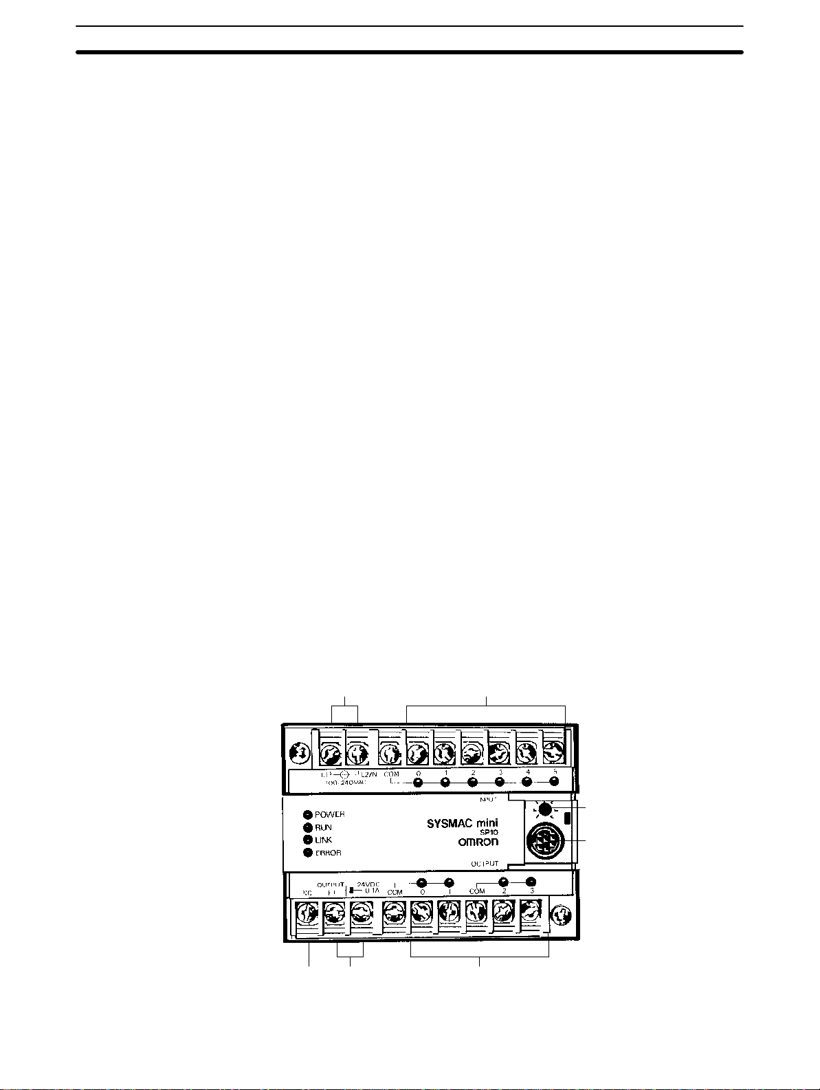
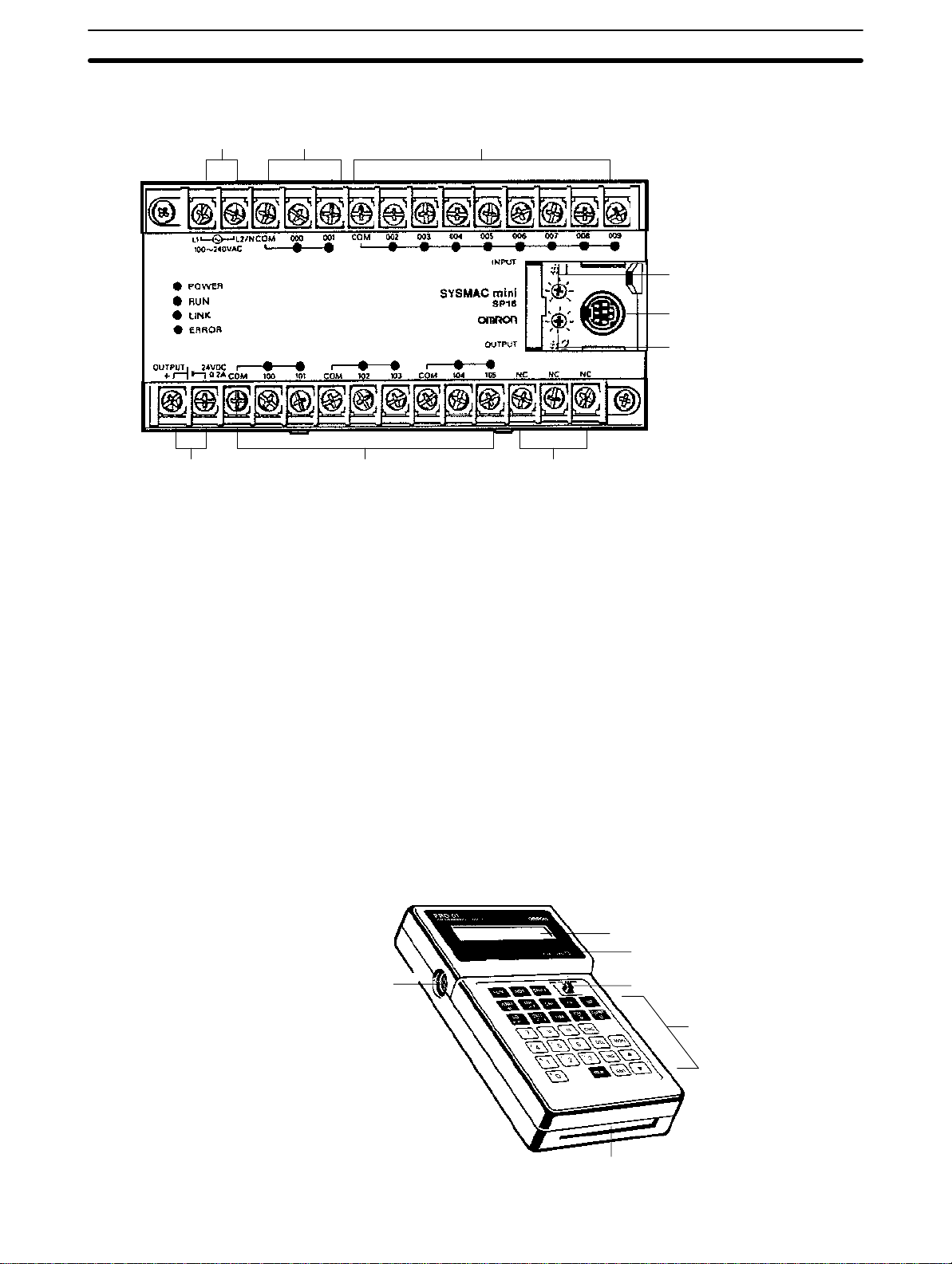
The SP-series PCs are shown below. Four models are available for each:
two powered by a 100- to 240-VAC power supply and the other two powered
by a 24-VDC power supply. Refer to
Appendix A Standard Models
for details.
SP10
Power supply Inputs
Power terminals
for external supply
24 VDC, 0.1 A (see note 1)
OutputsNC
Analog timer
setting adjustment
Programming Console/
Link Adapter connector
5
Units Section 1-3
SP16 and SP20 The SP20 is essentially the same as the SP16. The SP16 is shown below.
Power supply
Power terminals
for external supply
24 VDC, 0.2 A (see note 1)
RDM(23) input
(See note 3)
Note 1. The power terminals for external supply are provided for the 100 to 240
Inputs
Analog timer 1
setting adjustment
Programming Console/
Link Adapter connector
Analog timer 2
setting adjustment
Outputs NC
VAC model (SP__-__-A) only.
2. Connect nothing to the NC terminal.
3. Input 000 is the counter input and 001 is the hard reset input for the RE-
VERSIBLE DRUM COUNTER, RDM(23). When RDM(23) isn’t being
used, these terminals can be used as normal input points but the input
signal must be below 1 kHz.
Indicators The PC has four indicators on the front panel, POWER, RUN, LINK, and ER-
ROR. The functions of the indicators are presented as follows.
POWER (green): Lit while power is supplied.
RUN (green): Lit when the PC is in RUN mode and operating normally.
LINK(green): Lit when the PC Link is operating normally.
ERROR(red): Lights when self-diagnosis detects an error. The PC will
stop operating.
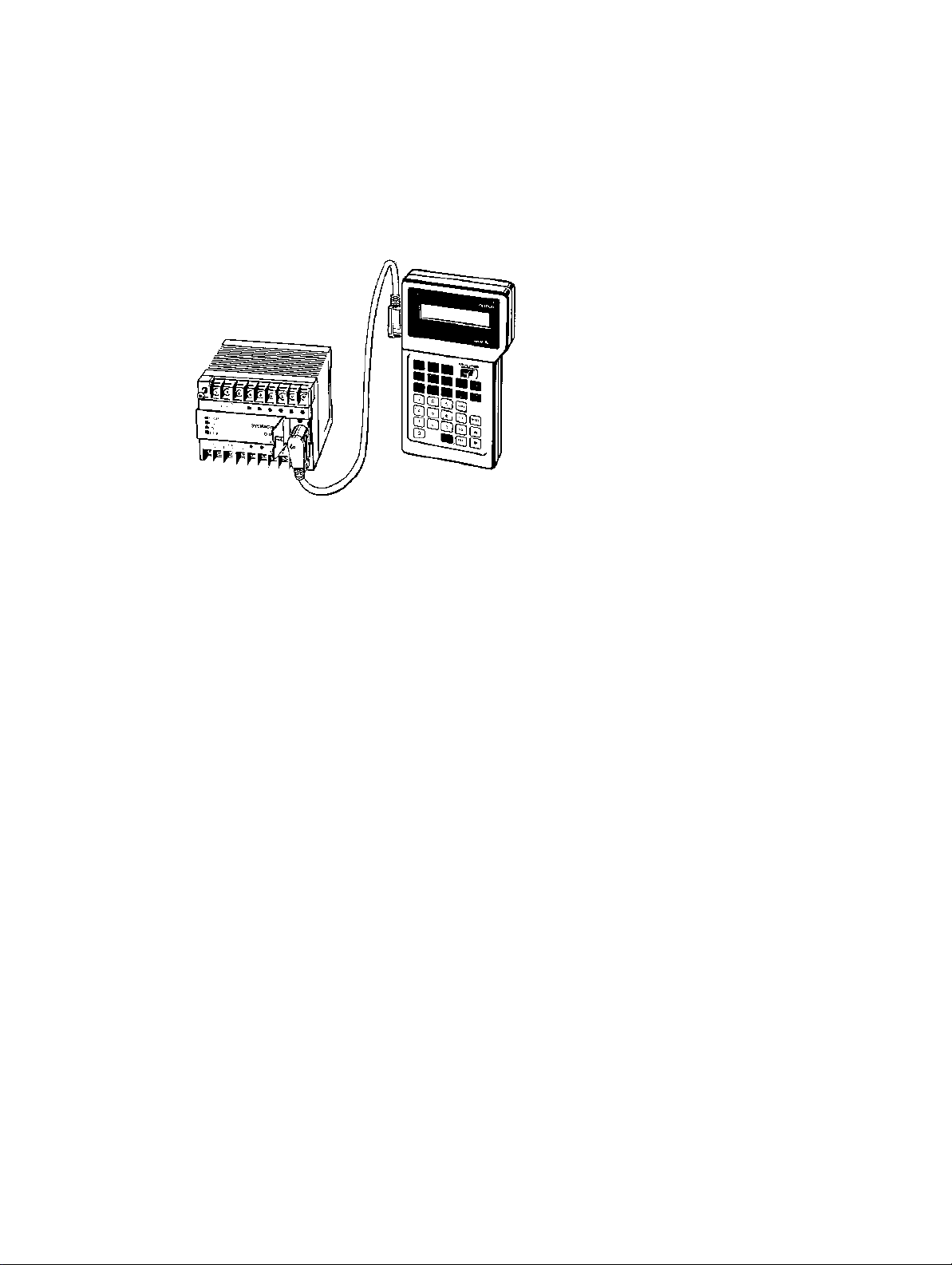
1-3-2 Programming Console
The Programming Console is shown below.
Display
Memory card access indicator
Connecting
cable connector
Mode switch
Key pad
Memory card slot
6
Units Section 1-3
The Programming Console is used to write and transfer programs to the PC.
It is also used to monitor operation and modify data. The Programming Console can be connected directly to the PC for single PCs. It can also be connected via a Link Adapter when PCs are connected in a PC Link configuration to access each PC individually without reconnection.
Note PCs connected to a Link Adapter cannot be directly connected to a Program-
ming Console. The Programming Console is connected to the Link Adapter.
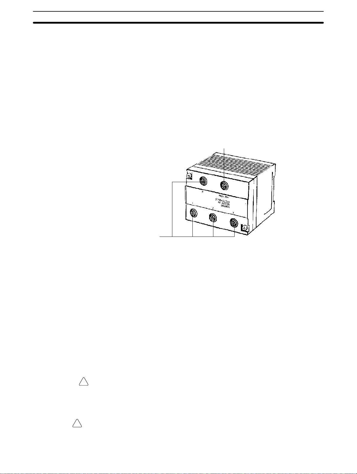
1-3-3 Link Adapter
The Link Adapter is shown below. The Link Adapter is used to link up to four
CPUs so that data can be transferred between the CPUs and so that all of
the CPUs can be accessed from the Programming Console from a single
connection point. For details refer to
1-4 PC Configuration
Programming Console
Connecting Cable Connector
.
CPU Connecting
Cable Connectors
1-3-4 Memory Cards
The Programming Console provides the ability to backup programs. The
Memory Card slot located at the base of the keyboard allows programs to be
transferred directly to and from the Programming Console. Each Card has a
built-in battery to preserve data.
Only one model of Memory Card, HMC-ES141, may be used. Each Memory
Card has 16 Kbytes of S-RAM. One Memory Card can hold up to 26 SP10
programs or up to 18 SP16 or SP20 programs.
A battery is built-in to the Memory Card to allow the data to be retained. The
battery must be replaced within five years to ensure data is not lost. To remove the battery, insert a sharp object, like a pen tip, into the hole at the bottom right of the card. The new battery must be inserted within one minute of
removing the old one.
Memory Cards have a write-protect switch. When the switch is ON, writing
operations to the memory card will not be possible.
Caution While the Memory Card is being accessed, the M/C ON LED on the Program-
!
ming Console will be lit. If the Memory Card is removed out from the Programming Console while the LED is ON, the data contained in memory on the Card
may be damaged.
WARNING Do not short the positive and negative terminals, charge, take apart, or throw
!
into fire a Memory Card. The battery inside the card may explode, burst into fire,
or leak, causing a potentially dangerous or even fatal accident.
7
PC Configuration Section 1-4
1-4 PC Configuration
The SP-series PCs can be configured to control a control system of from 10
through 80 I/O points. An SP10 provides 10 I/O points (6 input and 4 output
points), an SP16 provides 16 I/O points (10 input and 6 output points), and
an SP20 provides 20 I/O points (12 input and 8 output points). A maximum of
4 SP-series PCs can be linked together via a Link Adapter, making a maximum of 80 I/O points with 4 SP20s.
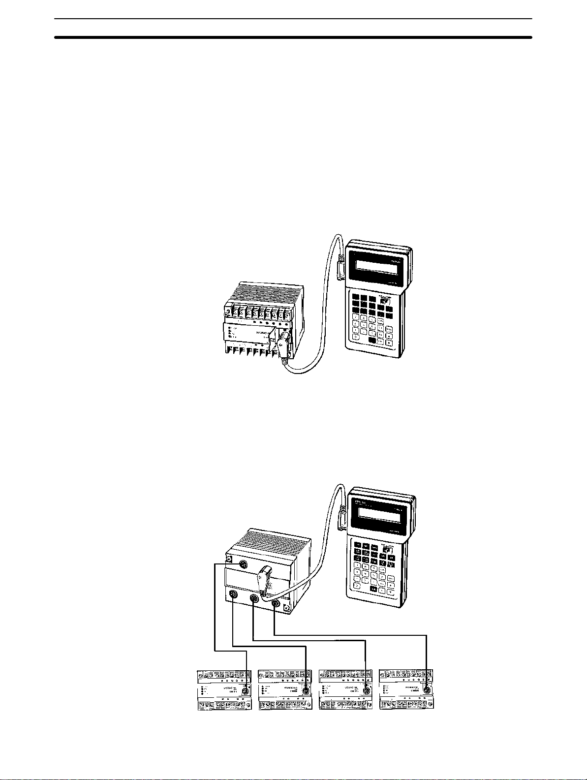
1-4-1 Basic Configuration
When only one SP-series PC is used, the number of I/O points available is
10 with the SP10, 16 with the SP16, or 20 with the SP20. Here, the Programming Console is connected directly to the CPU for programming and operation.
Connecting Cable
SP10-CN__1
PC
SP10-PRO01-V1
1-4-2 Expanded System Configuration: PC Links
Up to four PCs can be linked with a Link Adapter to increase the number of
I/O points to 80 maximum. Although each PC still operates on its own program, no special programming is needed to transfer data between the PCs
via LR bits. Up to 128 bits of data (32 bits per PC) can be shared between
the PCs through their LR areas. Refer to
SP10-AL001
Link Adaptor
3-2-5 LR Area
for details on LR bits.
SP10-PRO01-V1
Programming
Console
SP10-CN__1 Connecting Cables
SP__ #0 SP__ #1 SP__ #2 SP__ #3
8

PC Configuration Section 1-4
Note 1. When two or more PCs are linked, apply power to all of the PCs at once
or to PC #0 last.
2. When using a Link Adapter, one PC must be connected to connector
number 0 on the Link Adapter.
3. Once CPUs are connected to the Link Adapter and turned ON, unit num-
bers are automatically assigned to the CPUs by the Link Adapter. Do not
change the point of connection of any CPU after a unit number has been
assigned to it. If CPUs are connected to a connecter for a different unit
number, unpredictable errors will occur during operation.
Unit Numbers When four PCs are linked, each are given a number from 0 through 3 de-
pending on which connector on the Link Adapter is used. PC #0 controls LR
data transfers between the PCs. The Programming Console is connected to
the Link Adapter and can program and monitor any of the four PCs.
9

SECTION 2
Installation
This section provides information on mounting and wiring the CPUs and on I/O specifications. Basic unit connections
are described in 1-4 PC Configuration. Detailed specifications are provided in Appendix B Specifications.
2-1 Dimensions 12 . . . . . . . . . . . . . . . . . . . . . . . . . . . . . . . . . . . . . . . . . . . . . . . . . . . . . . .
2-2 Installation 13 . . . . . . . . . . . . . . . . . . . . . . . . . . . . . . . . . . . . . . . . . . . . . . . . . . . . . . .
2-2-1 Installation Environment 13 . . . . . . . . . . . . . . . . . . . . . . . . . . . . . . . . . . . .
2-2-2 Cooling 14 . . . . . . . . . . . . . . . . . . . . . . . . . . . . . . . . . . . . . . . . . . . . . . . . .
2-2-3 Preventing Noise 14 . . . . . . . . . . . . . . . . . . . . . . . . . . . . . . . . . . . . . . . . . .
2-2-4 Mounting Requirements 15 . . . . . . . . . . . . . . . . . . . . . . . . . . . . . . . . . . . .
2-3 Wiring 15 . . . . . . . . . . . . . . . . . . . . . . . . . . . . . . . . . . . . . . . . . . . . . . . . . . . . . . . . . . .
2-3-1 Power Supply 15 . . . . . . . . . . . . . . . . . . . . . . . . . . . . . . . . . . . . . . . . . . . .
2-3-2 I/O Connections 16 . . . . . . . . . . . . . . . . . . . . . . . . . . . . . . . . . . . . . . . . . . .
2-3-3 Precautions 20 . . . . . . . . . . . . . . . . . . . . . . . . . . . . . . . . . . . . . . . . . . . . . .
2-4 Programming Console 20 . . . . . . . . . . . . . . . . . . . . . . . . . . . . . . . . . . . . . . . . . . . . . .
2-4-1 Designating the PC 21 . . . . . . . . . . . . . . . . . . . . . . . . . . . . . . . . . . . . . . . .
2-4-2 Input Filters 22 . . . . . . . . . . . . . . . . . . . . . . . . . . . . . . . . . . . . . . . . . . . . . .
11
Dimensions Section 2-1
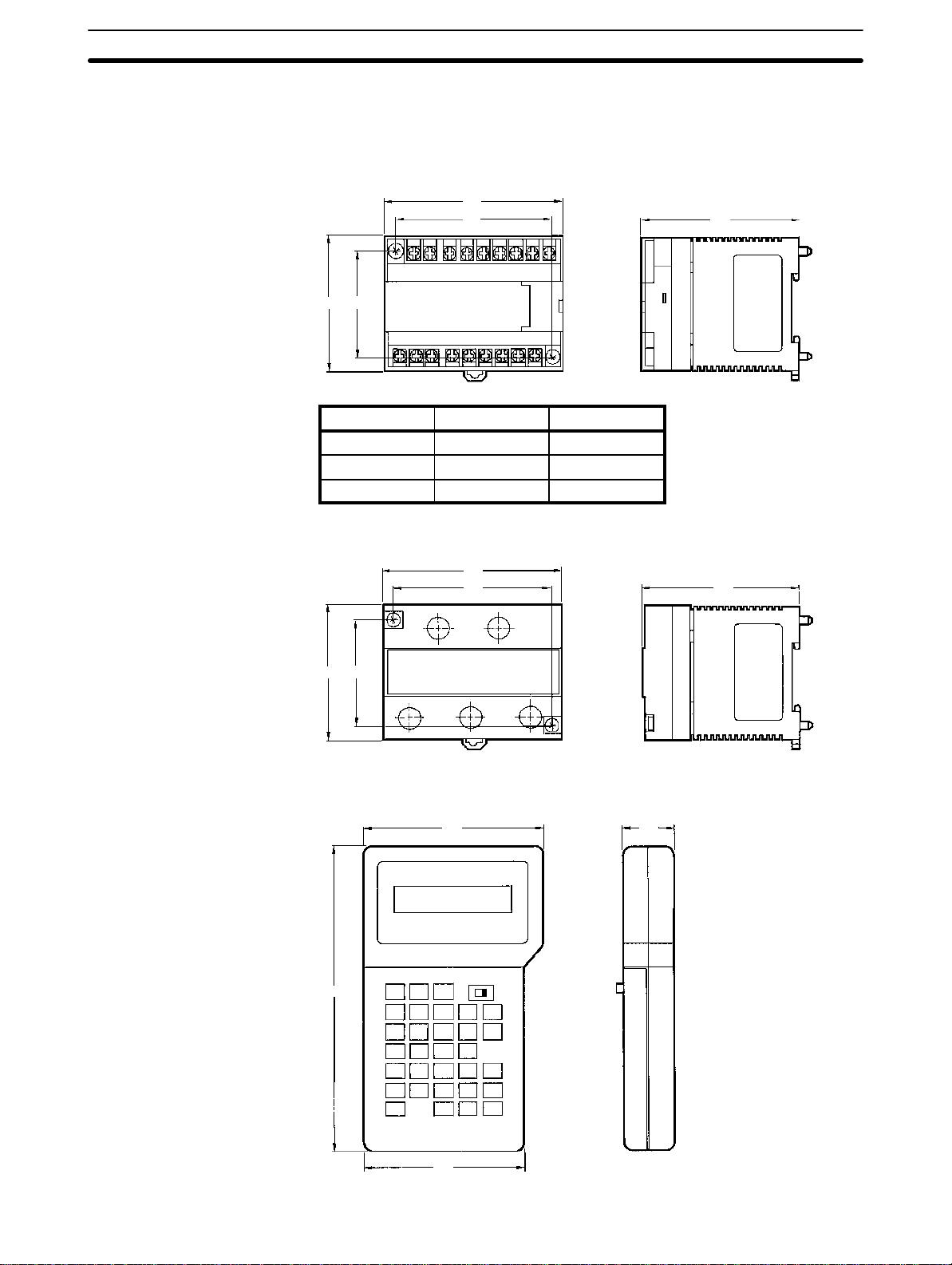
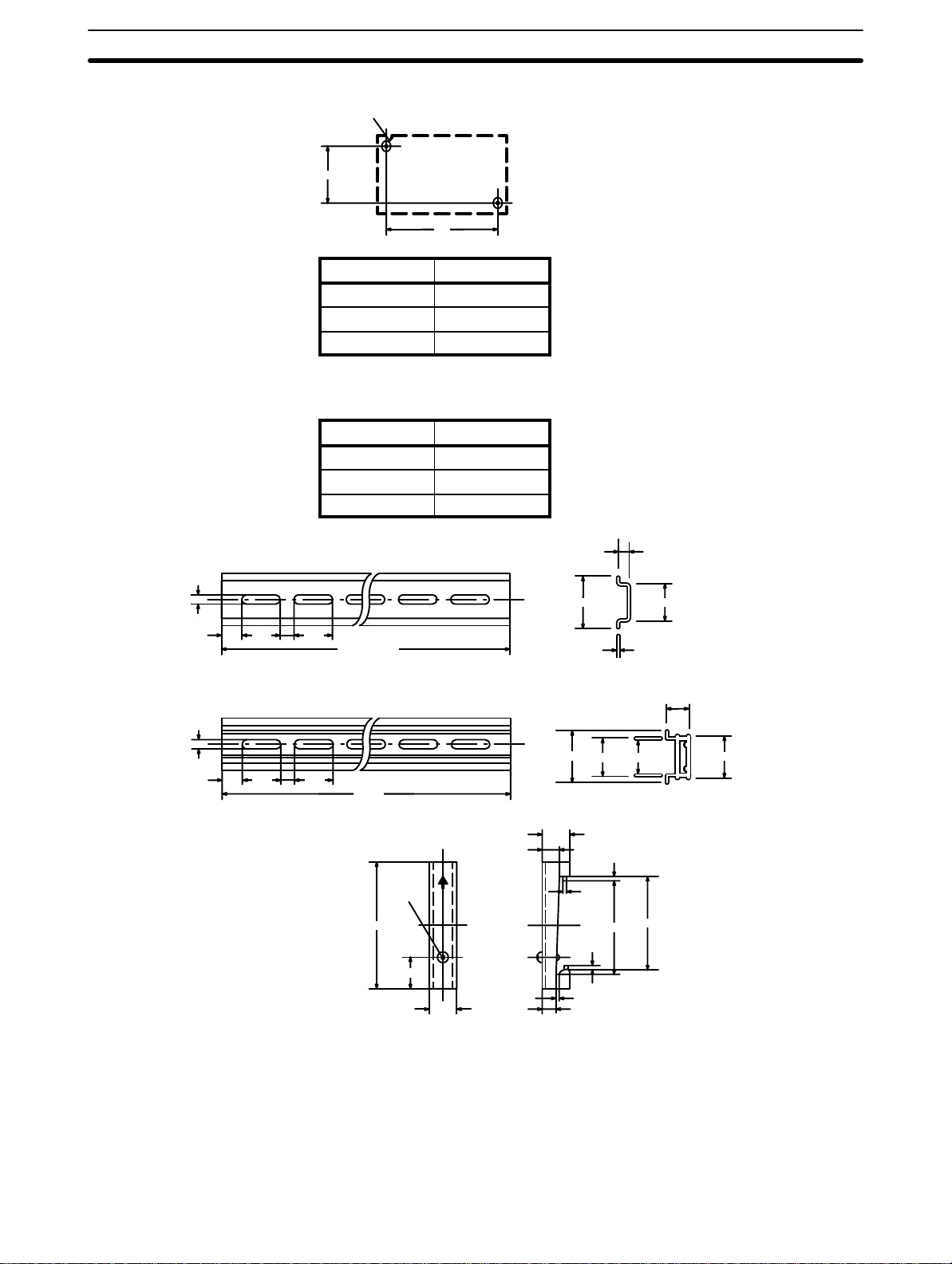
2-1 Dimensions
This section gives mounting dimensions. All dimensions are in millimeters.
CPUs
Link Adapter
SP10-D_-_, SP16-D_-_, SP20-D_-_
A
B
68 53
PC model Dimension A Dimension B
SP10-D_-_ 92 81
SP16-D_-_ 135 124
SP20-D_-_ 160 149
SP10-AL001
92
81
81
81
Programming Console
68 53
SP10-PRO01-V1
155
91
25
12
81
Installation Section 2-2
Surface Mounting Dimensions
2-M4
53
A
PC model Dimension A
SP10-D_-_ 81
SP16-D_-_ 124
SP20-D_-_ 149
Mounting Track
The SP-series PCs can be mounted onto DIN Tracks.
Model No. Length (L)
PFP-50N 50 cm
PFP-100N 1 m
PFP-100N2 1 m
PFP-50N/PFP-100N
4.5
25 25
15
10
PFP-100N2
4.5
25 25
15
10
1000 (500) *
1000
End Plate (PFP-M)
M4x8
50
11.5
10
7.3±0.15
35±0.3 27±0.5
35±0.3
27 24
10
6.2
1.8
1
35.5
1.8
1.3
4.8
1
16
29.2
35.3
2-2 Installation
2-2-1 Installation Environment
Although the SP-series Programmable Controllers are highly reliable and
durable, a number of factors should be considered when installing them. Do
not expose an SP-series PC to the following conditions.
13
Installation Section 2-2
• An ambient temperature that falls below 0° or exceeds 55°C for the CPU, or
that falls below 0°or exceeds 45°C for the Programming Console.
• Abrupt changes in temperature that cause condensation.
• A relative humidity less than 10% or greater than 90%.
• Corrosive or flammable gas.
• Dust, salt, or iron particles.
• Direct vibration or shock.
• Direct sunlight.
• Splashes of water, oil, or chemicals.
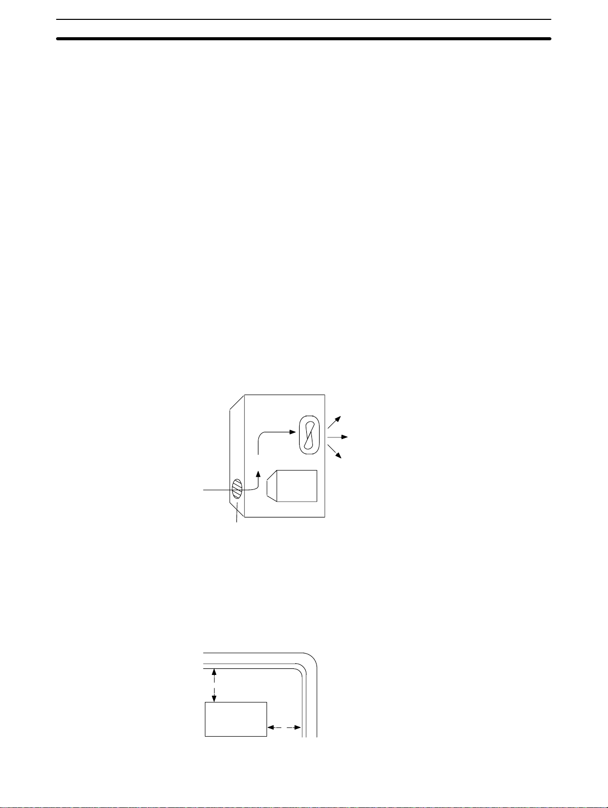
2-2-2 Cooling
There are two points to consider in order to ensure that the PC does not
overheat. The first is the clearance between the CPUs and control panel surround them, and the second is the installation of a cooling fan.
Clearance The CPUs need to have sufficient room between them to allow for I/O wiring,
and additional room to ensure that the wiring does not hamper cooling. The
CPU’s must be mounted close enough so that the length of the Connecting
Cable between any CPU and the Link Adapter does not exceed 4 meters.
Cooling Fan Ensure adequate ventilation is provided for the PCs. A cooling fan is not al-
ways necessary, but may be needed if the PC is mounted in a warm or enclosed area or over a source of heat. Although it is best to avoid installing the
PC in a warm area, use a cooling fan or an air conditioner, as shown in the
following illustration, to maintain the ambient temperature within specifications.
2-2-3 Preventing Noise
In order to prevent noise from interfering with the operation of the PC, use
AWG 14 twisted-pair cables (cross-sectional area of at least 2 mm
mount the PC in a control panel in which high-power equipment is installed
and make sure the point of installation is at least 200 mm away from power
cables, as shown in the following diagram. Ground the panel to which the PC
is mounted.
Control Panel
Louver
Power lines
200 mm min.
PC
Fan
2
). Do not
14
PC
200 mm min.
Wiring Section 2-3
Whenever possible, use wiring conduit to hold the I/O wiring. Standard wiring
conduit should be used, and it should be long enough to completely contain
the I/O wiring and keep it separated from other cables.
2-2-4 Mounting Requirements
The system consists of from one to four CPUs and, if more than one CPU is
used, a Link Adapter. The Units may be mounted horizontally or vertically, as
desired. Do not mount a Unit on its side. The Unit should be mounted with
the printing on the front panel oriented as it would normally be read. The PC
can be mounted using DIN Track or mounted directly to any sturdy support
meeting the environmental specifications listed in
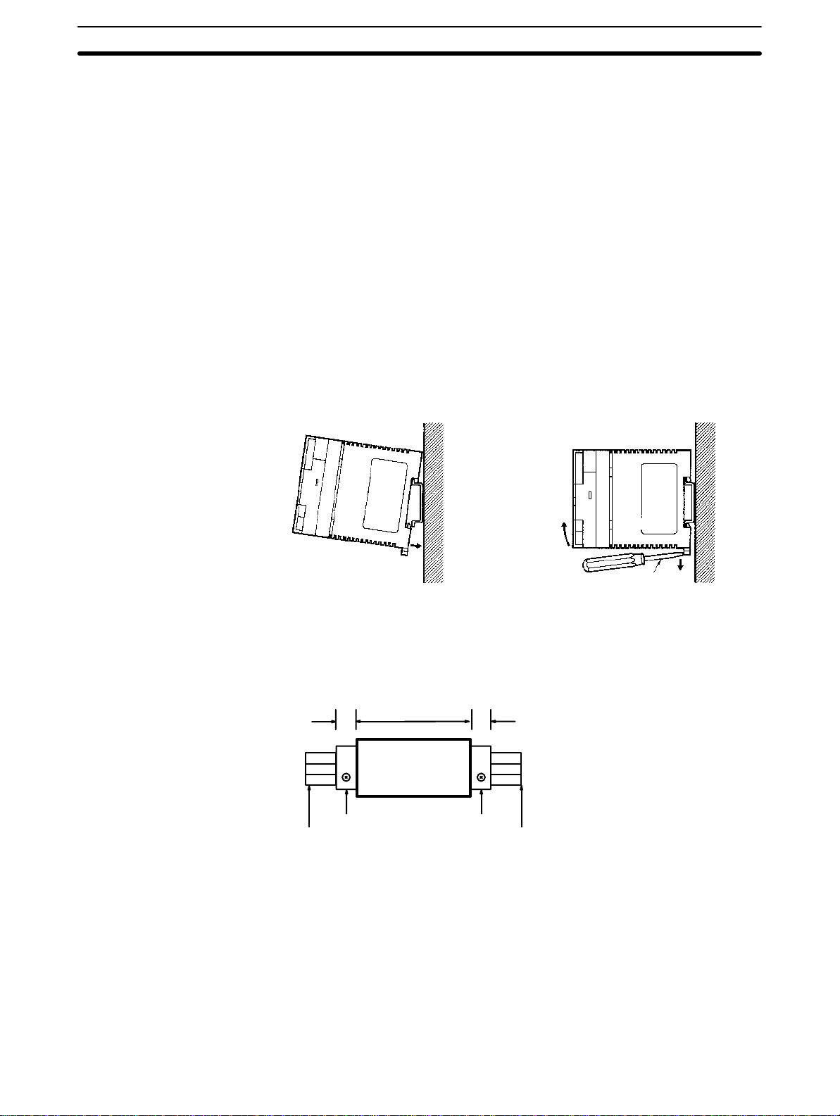
Track Mounting The PC may be mounted using DIN Track if desired. Use DIN Track 35 mm
wide. There is a groove on the back of the Unit that is used to attach it to the
DIN Track. When mounting to DIN Track, be sure to remove the mounting
screws.
Appendix B Specifications.
RemovalMounting
Note Remove the mounting screws when mounting on a track.
2-3 Wiring
Note Do not wire the terminal marked “NC.”
2-3-1 Power Supply
Screwdriver
Engage the top hook to the
track and push the PC in until
the bottom hook locks onto the
track.
Push down the bottom hook
with a screwdriver and push
the PC upward.
Attach an End Plate to the left and right sides of the Unit to hold it in place.
1010
SP-series PC
PFP-M End Plate
DIN Track DIN Track
PFP-M End Plate
DIN Track
PFP-100N (1 m)
PFP-50N (0.5m)
PFP-100N2 (1 m)
Use independent power sources for the inputs, the output loads, and the PC.
Voltage fluctuations caused by current surges to motors may affect operation
of the PC. When using more than one PC, use a separate power supply for
15
Wiring Section 2-3
each PC, firstly to prevent voltage drops caused by surge currents and secondly, to prevent the breaker from malfunctioning.
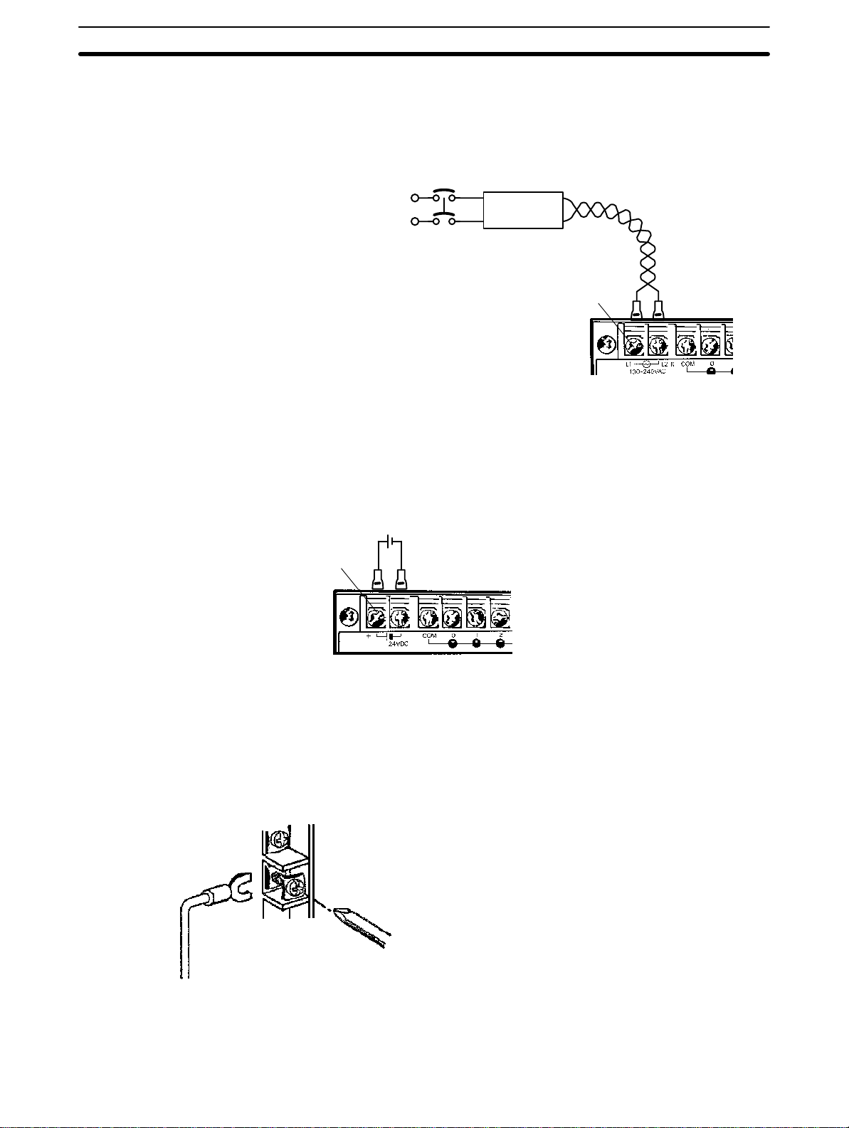
The following diagrams show the proper way to connect the power source to
the PC. Refer to
AC Connections
Appendix B Specifications
for detailed specifications.
AC Power Source
• Supply 100 to 240
VAC, 50/60 Hz
Breaker
Power Line
1:1 Isolation
Transformer
M3.5 screws
• Use twisted pair cable
(cross-sectional area of
2
2 mm
min.)
To reduce noise interference from the power lines, use twisted pair cables.
Noise can also be significantly reduced by connecting a 1-to-1 isolation
transformer.
Note Do not short the positive and negative lines.
DC Connections Supply 24 VDC and keep voltage fluctuations within the specified range.
+
M3.5 screws
2-3-2 I/O Connections
Connect the I/O devices to the I/O terminals using wire with a cross-sectional
area of 1.04 to 2.63 mm
self-rising pressure plates. Connect the lead wires to the terminals as shown
below. Tighten the screws with a torque of 8 kg-cm maximum.
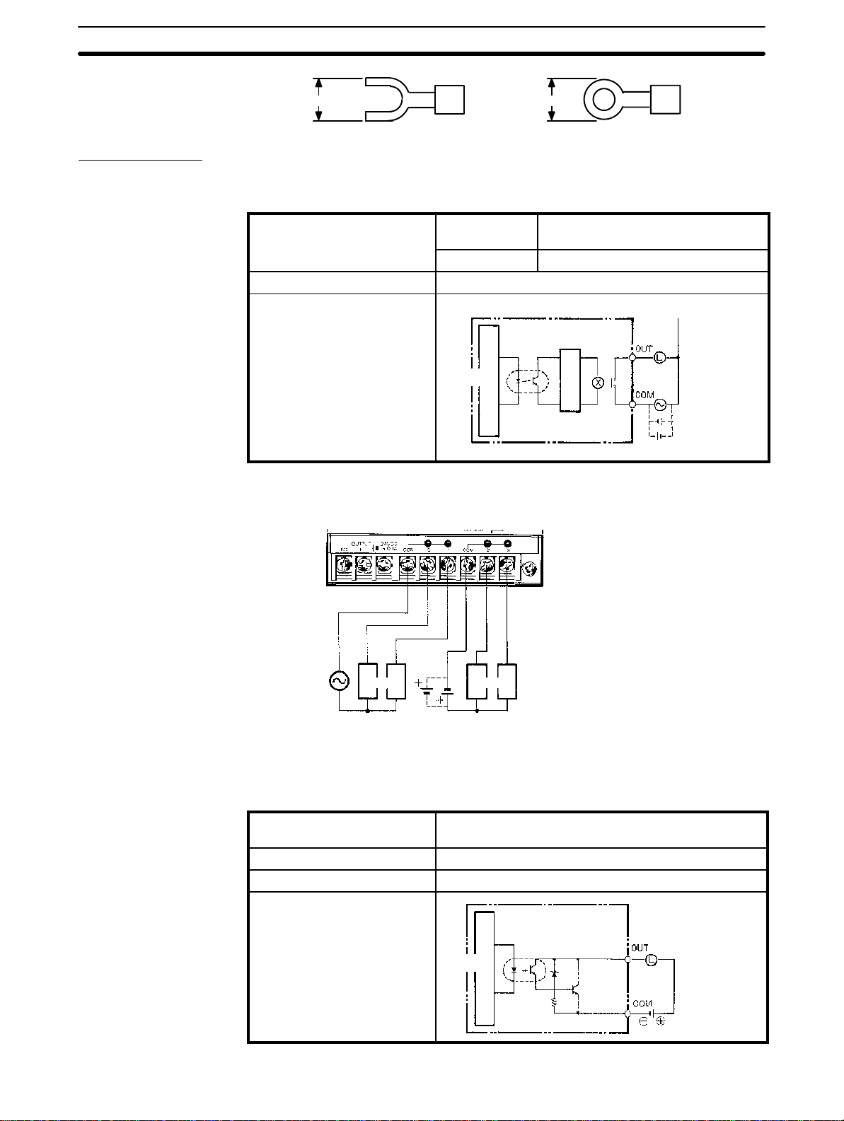
If you wish to attach solderless type terminals to the ends of the lead wires,
use terminals having the following dimensions.
16
2
. The terminals have screws with M3.5 heads and
Wiring Section 2-3
7.5 mm max.7.5 mm max.
Output Circuits
Refer to
Relay Contact Outputs
Maximum switching
capacity
Minimum switching capacity 5 VDC, 100 mA
Circuit configuration
Appendix B Specifications
Resistive loads 250 VAC, 2 A (cosf=1), 24 VDC, 2A/pt
Inductive loads 250 VAC, 0.5 A (cosf=0.4)/pt
for detailed specifications.
Insulating
Photocoupler
Internal
circuit
Relay’s power (24 V)
is internally supplied
The following example uses an SP10 CPU.
250 VAC
max.
Loads
AC load
power supply
24 VDC
Loads
DC load
power supply
Internal
circuit
Use seperate
power supplies
for load power
sources
250 VAC,
24 VDC max.
Transistor Outputs
Maximum switching
24 VDC
+10%
capacity
Leakage current 0.1 mA max.
Residual voltage 1 V max.
Circuit configuration
Internal
circuit
/
–15%
Insulating
photocoupler
, 0.3 A
24 VDC
17
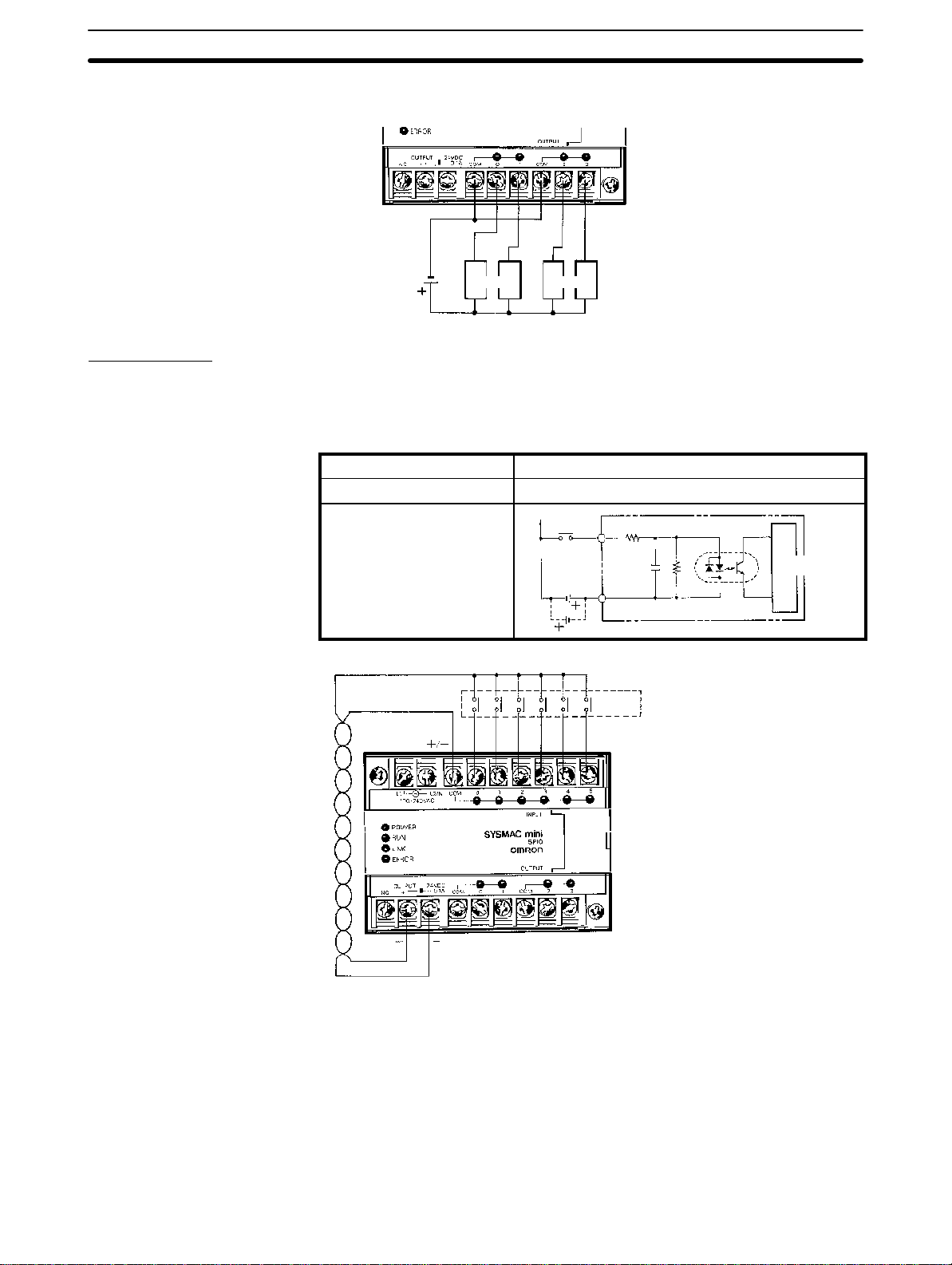
Wiring Section 2-3
The following example uses an SP10 CPU.
Input Circuits
Load power
supply 24 VDC
Loads Loads
Either positive or negative poles of the power supply can be connected to the
common (COM) terminals, enabling connection of both PNP (negative common) and NPN (positive common) inputs.
24 VDC
+10%
COM
/
–15%
3.3 kΩ 470 ΩIN
1,000 pF
Insulating
photocoupler
Input devices
Internal
circuit
Input voltage 24 VDC
Input current 7 mA Typ. (24 VDC)
Circuit configuration
18
The power source of the SP10 for external supply is rated at 0.1 A, 24 VDC
max., and the power source of the SP16 and SP20 is rated at 0.2 A, 24 VDC
max. The input circuit consumes about 7 mA (typ. at 24 VDC) per input point.
Transistor outputs with a current consumption up to 0.2 A can be used with
the SP10, and a current consumption up to 0.32 A with the SP16 and SP20.
Relay contact outputs require a current of 0.013 A each, so when all of the
relays are ON, the external power supply capacity is 0.1 A for the SP10 and
0.2 A for the SP16 and SP20. When using the SP10 as the power source for
Wiring Section 2-3
input devices such as sensors, etc., make sure that the power consumption
of the devices does not exceed the ratings of the PC.
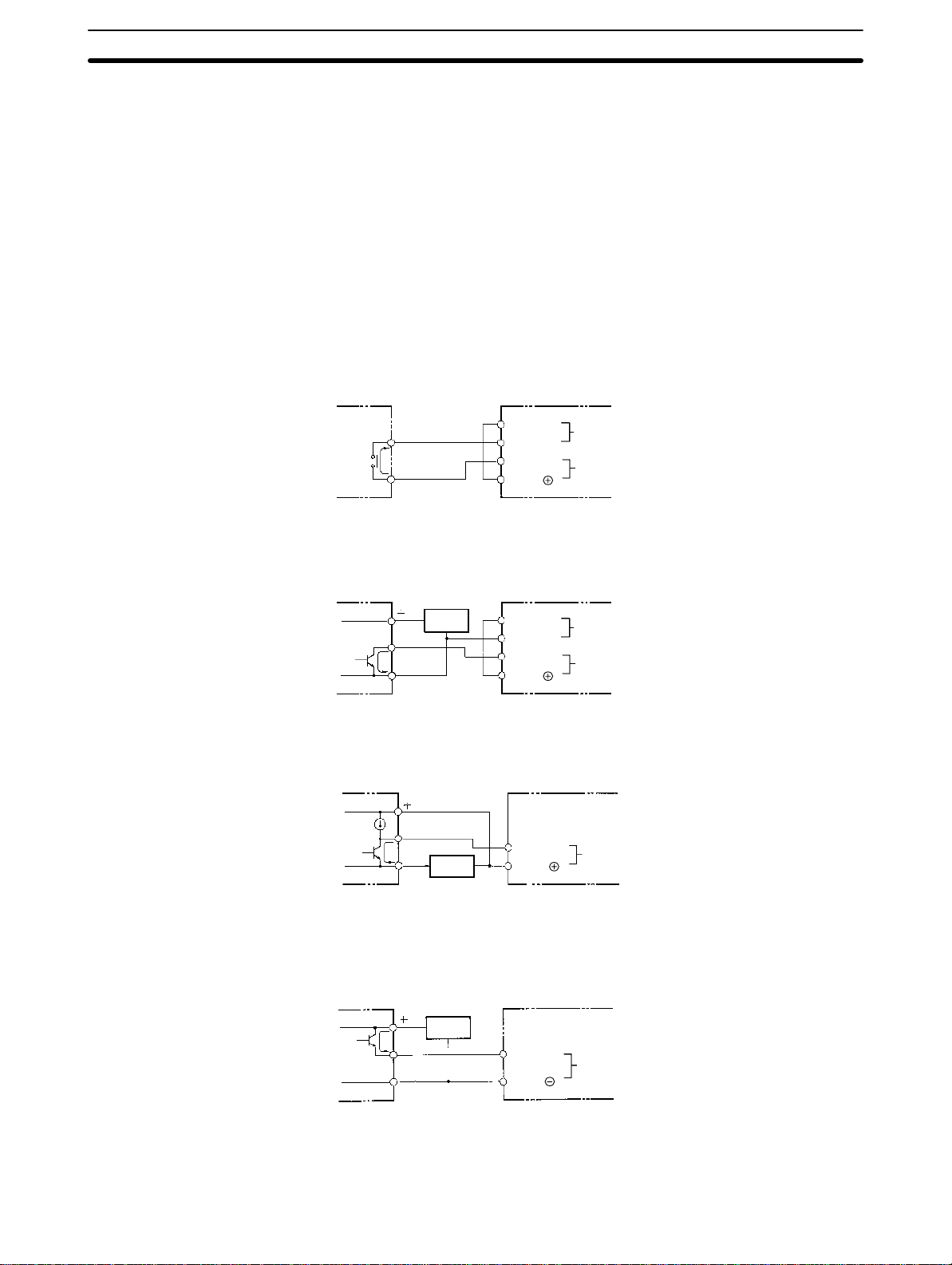
DC Input Examples The following diagrams show the correct way to wire the terminals on the
CPU. When wiring, work carefully to ensure that all terminals are wired correctly. If an input device is connected to an output point, damage may result.
Appen-
DC Input Devices
Check all I/O devices to ensure they meet the specifications (refer to
Specifications).
dix B
The DC inputs in the following diagrams are NPN (positive common). Reverse the polarity if PNP (negative common) is used.
Use the CPU’s 24 VDC power supply output to supply power to inputs. If the
maximum output current of 0.3 A is not sufficient, use a separate DC power
supply.
NPN Open-collector Outputs
NPN Current Outputs
Current
regulator
7 mA
Output
7 mA
0 V
Output
7 mA
0 V
Sensor
power
supply
Sensor
power
supply
24 VDC
0 V
IN
COM
24 VDC
0 V
IN
COM
Use the same power supply
for the input and sensor.
IN
COM
Power source for
external supply
DC input
Power source for
external supply
DC input
DC input
SP__
SP__
SP__
PNP Current Outputs
Sensor
power
supply
Output
7 mA
0 V
IN
COM
DC input
SP__
Note When using the DC model (SP__-D_-D), do not input the signal through a NC
contact (which makes the PC operate when the externally input signal turns
19
Programming Console Section 2-4
OFF). Proper operation for power interruptions will not be possible if NC contacts are used in conjunction with counter, shift, or keeping (latching) instructions.
2-3-3 Precautions
Unit Sticker A sticker is provided on the upper face of the CPU to prevent foreign objects,
such as wire clippings, from entering the CPU. Leave this protective sticker
on until the CPU is ready for operation. The sticker must be removed before
operation to enable proper cooling.
Contact Outputs High inductance on for contact outputs will reduce relay life. Keep inductance
low and use an arc suppressor (such as a diode for DC loads). This is particular important with inductive DC loads.
Vibration Relay operation may be adversely affected if the relay is located near contac-
tors, valves, motors, or other devices that produce vibration.
Protective Circuits We recommend the use of arc suppressors to increase contact life and allevi-
ate the affects of noise. Arc suppressors, however, will delay release time
somewhat and, if used incorrectly, they can inhibit proper operation. The
most common arc suppressors for AC are capacitor-resistor circuits and varistor circuits; for DC: capacitor-resistor circuits, diode circuits, and varistor
circuit. Do not use a capacitor without a resistor as the charging current flow
to the capacitor when current is turned ON can cause the contacts to fuse.
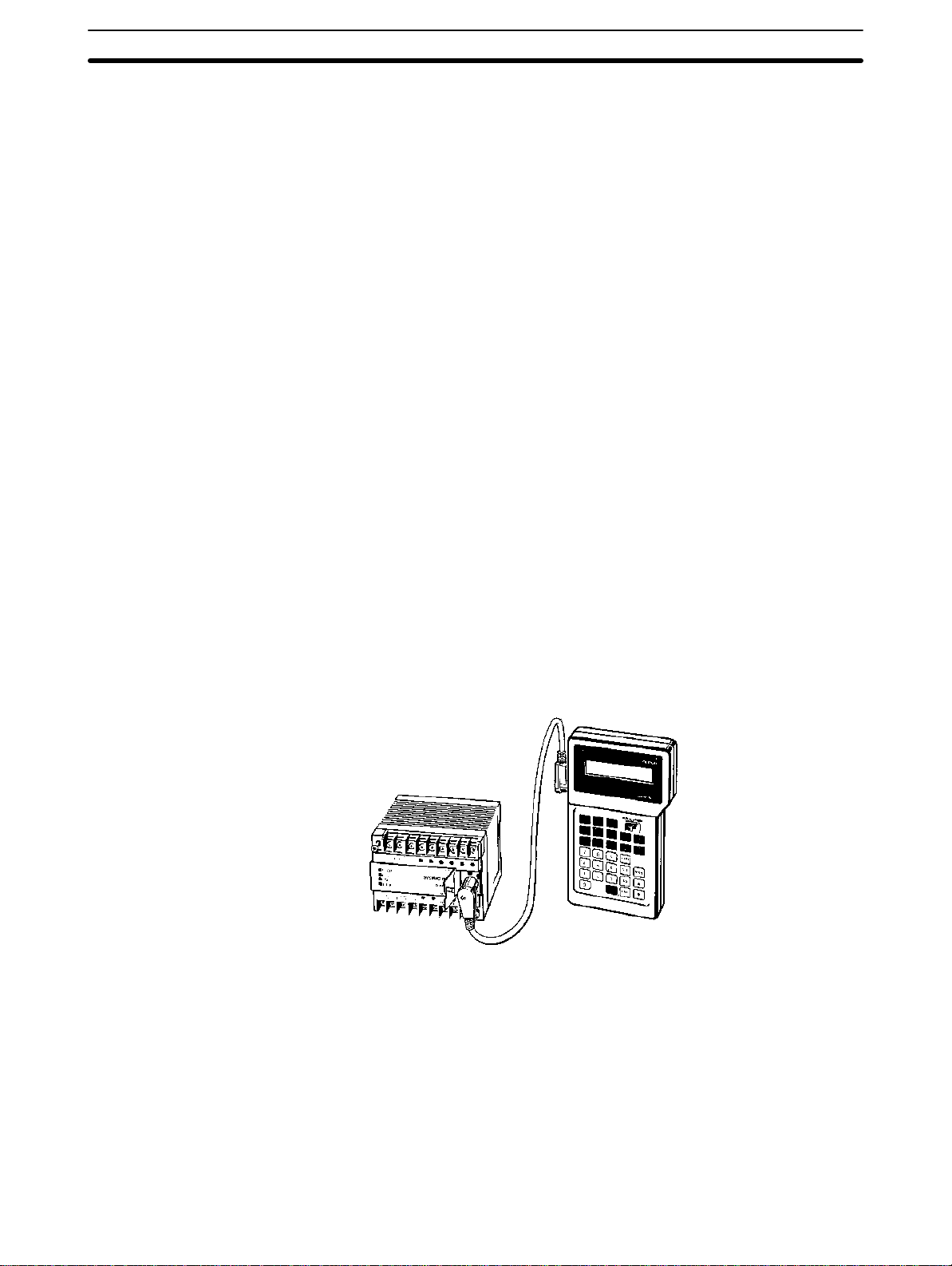
2-4 Programming Console
Open the connector cover of the PC, align the notch on the connector, and
press the connector into place.
Connection to a CPU
Connecting Cable
SP10-CN__1
PC
SP__
SP10-PRO01-V1
20
Programming Console Section 2-4
Connection to a Link Adaptor
SP10-AL001
Link Adaptor
SP10-PRO01-V1
Programming
Console
SP10-CN__1 Connecting Cables
SP__ #0 SP__ #1 SP__ #2 SP__ #3
Connecting Cable Use one of the following Connecting Cables to connect the Programming Console.
SP10-CN221 (2 m)
SP10-CN421 (4 m)
Note The sum of the cable lengths between Unit #0 and the Link Adapter and be-
tween the Link Adapter and the Programming Console must be 4.2 m maximum.
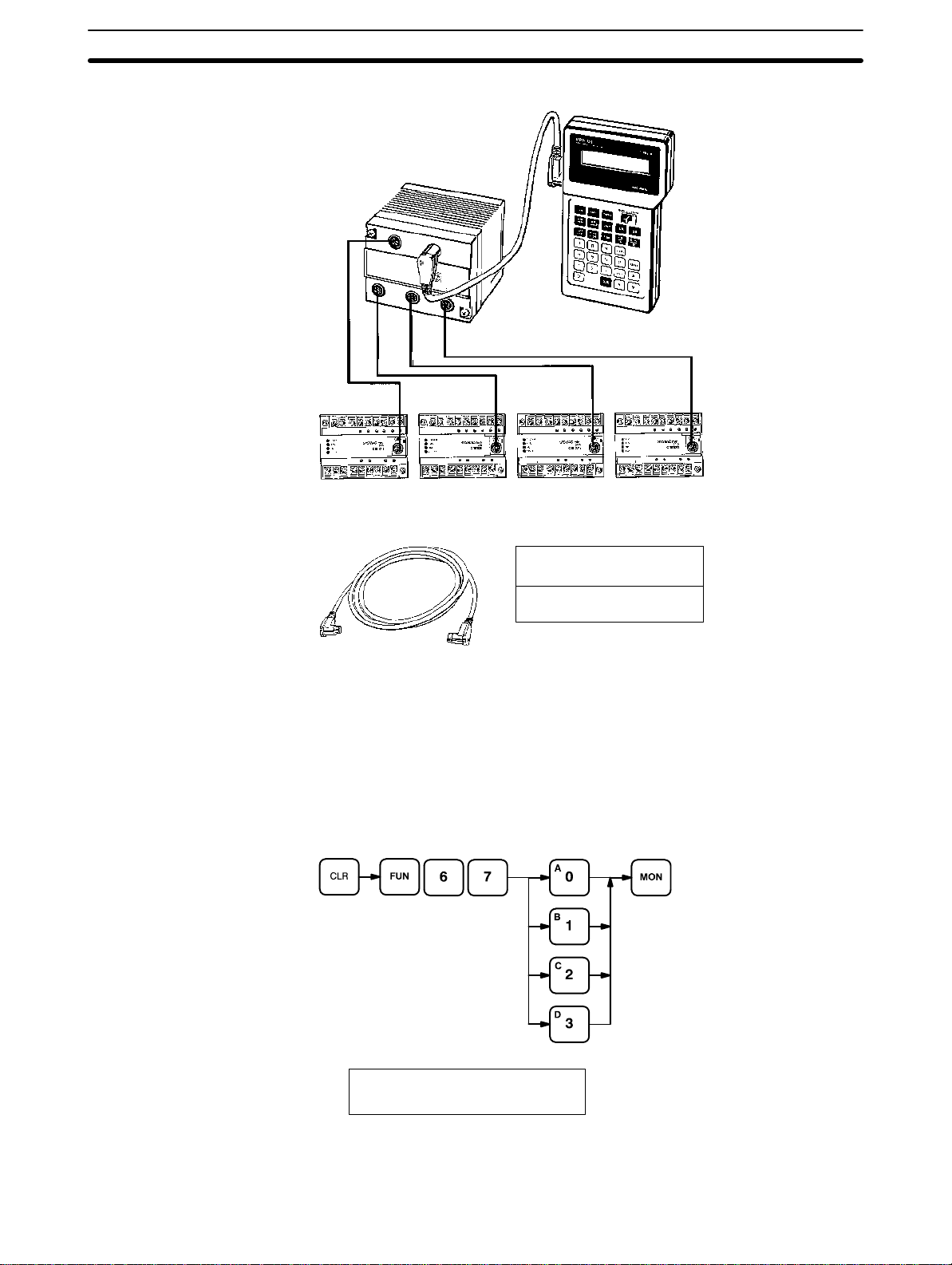
2-4-1 Designating the PC
Any of the PCs connected in a PC Link may be accessed through the Link
Adapter using the Programming Console. Use the following key sequence to
specify the number of the desired PC. The PC can be designated in either
PROGRAM or RUN mode.
AB
0 PC 0-3? PC ?
A
The PC’s operation or operation mode is not affected by changing the PC
designation. When the mode switch of the Programming Console and the
21
 Loading...