


 Loading...
Cat. No. V063-E1-03
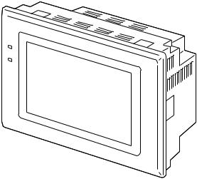
NT631 and NT631C
Programmable Terminals
Setup Manual
NT631 and NT631C
Programmable Terminals
Setup Manual
Revised September 2007
POWER
RUN
iv
Notice:
OMRON products are manufactured for use according to proper procedures by a qualified operator and only for the purposes described in this manual.
The following conventions are used to indicate and classify precautions in this manual. Always heed the information provided with them. Failure to heed precautions can result in injury to people or damage to property.
!DANGER Indicates an imminently hazardous situation which, if not avoided, will result in death or serious injury. Additionally, there may be severe property damage.
!WARNING Indicates a potentially hazardous situation which, if not avoided, could result in death or serious injury. Additionally, there may be severe property damage.
!Caution Indicates a potentially hazardous situation which, if not avoided, may result in minor or moderate injury, or property damage.
OMRON Product References
All OMRON products are capitalized in this manual. The word “Unit” is also capitalized when it refers to an OMRON product, regardless of whether or not it appears in the proper name of the product.
The abbreviation “Ch,” which appears in some displays and on some OMRON products, often means “word” and is abbreviated “Wd” in documentation in this sense.
The abbreviation “PLC” means Programmable Controller. “PC” is used, however, in some Programming Device displays to mean Programmable Controller.
Visual Aids
The following headings appear in the left column of the manual to help you locate different types of information.
Note Indicates information of particular interest for efficient and convenient operation of the product.
1,2,3... 1. Indicates lists of one sort or another, such as procedures, checklists, etc.
OMRON, 2000
All rights reserved. No part of this publication may be reproduced, stored in a retrieval system, or transmitted, in any form, or by any means, mechanical, electronic, photocopying, recording, or otherwise, without the prior written permission of OMRON.
No patent liability is assumed with respect to the use of the information contained herein. Moreover, because OMRON is constantly striving to improve its high-quality products, the information contained in this manual is subject to change without notice. Every precaution has been taken in the preparation of this manual. Nevertheless, OMRON assumes no responsibility for errors or omissions. Neither is any liability assumed for damages resulting from the use of the information contained in this publication.
v
vi
|
TABLE OF CONTENTS |
|
PRECAUTIONS . . . . . . . . . . . . . . . . . . . . . . . . . . . . . . . . . . . |
xv |
|
1 |
Intended Audience . . . . . . . . . . . . . . . . . . . . . . . . . . . . . . . . . . . . . . . . . . . . . . . . . . . . . . . . . |
xvi |
2 |
General Precautions . . . . . . . . . . . . . . . . . . . . . . . . . . . . . . . . . . . . . . . . . . . . . . . . . . . . . . . . |
xvi |
3 |
Safety Precautions . . . . . . . . . . . . . . . . . . . . . . . . . . . . . . . . . . . . . . . . . . . . . . . . . . . . . . . . . |
xvi |
SECTION 1 |
|
|
General. . . . . . . . . . . . . . . . . . . . . . . . . . . . . . . . . . . . . . . . . . . |
1 |
|
1-1 Role and Operation of the NT631/NT631C . . . . . . . . . . . . . . . . . . . . . . . . . . . . . . . . . . . . . |
2 |
|
1-2 Functions of the NT631/NT631C . . . . . . . . . . . . . . . . . . . . . . . . . . . . . . . . . . . . . . . . . . . . . |
4 |
|
1-3 |
System Configuration . . . . . . . . . . . . . . . . . . . . . . . . . . . . . . . . . . . . . . . . . . . . . . . . . . . . . . |
16 |
1-4 Communications with the Host . . . . . . . . . . . . . . . . . . . . . . . . . . . . . . . . . . . . . . . . . . . . . . . |
18 |
|
1-5 Communications Using Memory Links . . . . . . . . . . . . . . . . . . . . . . . . . . . . . . . . . . . . . . . . |
21 |
|
1-6 |
Before Operating . . . . . . . . . . . . . . . . . . . . . . . . . . . . . . . . . . . . . . . . . . . . . . . . . . . . . . . . . . |
23 |
SECTION 2 |
|
|
Preparing for Connection . . . . . . . . . . . . . . . . . . . . . . . . . . . |
25 |
|
2-1 Method for Connection to the Host . . . . . . . . . . . . . . . . . . . . . . . . . . . . . . . . . . . . . . . . . . . . |
26 |
|
2-2 Names and Functions of Parts . . . . . . . . . . . . . . . . . . . . . . . . . . . . . . . . . . . . . . . . . . . . . . . . |
29 |
|
SECTION 3 |
|
|
Hardware Settings and Connections. . . . . . . . . . . . . . . . . . . |
31 |
|
3-1 |
Installation . . . . . . . . . . . . . . . . . . . . . . . . . . . . . . . . . . . . . . . . . . . . . . . . . . . . . . . . . . . . . . . |
32 |
3-2 Connecting to the Support Tool. . . . . . . . . . . . . . . . . . . . . . . . . . . . . . . . . . . . . . . . . . . . . . . |
35 |
|
3-3 |
Connecting a Printer . . . . . . . . . . . . . . . . . . . . . . . . . . . . . . . . . . . . . . . . . . . . . . . . . . . . . . . |
36 |
3-4 Connecting a Bar Code Reader . . . . . . . . . . . . . . . . . . . . . . . . . . . . . . . . . . . . . . . . . . . . . . . |
36 |
|
3-5 Using a Memory Unit . . . . . . . . . . . . . . . . . . . . . . . . . . . . . . . . . . . . . . . . . . . . . . . . . . . . . . |
39 |
|
SECTION 4 |
|
|
Connecting to the Host from the RS-232C Port. . . . . . . . . . |
47 |
|
4-1 Connecting to the RS-232C Port at the Host . . . . . . . . . . . . . . . . . . . . . . . . . . . . . . . . . . . . . |
48 |
|
SECTION 5 |
|
|
Connecting to the Host from the RS-422A/485 Port . . . . . . |
79 |
|
5-1 Connecting to the Host’s RS-232C Port . . . . . . . . . . . . . . . . . . . . . . . . . . . . . . . . . . . . . . . . |
80 |
|
5-2 Connecting to the Host’s RS-422A/485 Port. . . . . . . . . . . . . . . . . . . . . . . . . . . . . . . . . . . . . |
93 |
|
SECTION 6 |
|
|
System Menu Operation. . . . . . . . . . . . . . . . . . . . . . . . . . . . . |
127 |
|
6-1 System Menu Operation Flow . . . . . . . . . . . . . . . . . . . . . . . . . . . . . . . . . . . . . . . . . . . . . . . . |
129 |
|
6-2 |
Starting the NT631/NT631C . . . . . . . . . . . . . . . . . . . . . . . . . . . . . . . . . . . . . . . . . . . . . . . . . |
129 |
6-3 Operation Modes and the System Menu . . . . . . . . . . . . . . . . . . . . . . . . . . . . . . . . . . . . . . . . |
130 |
|
6-4 |
Memory Initialization . . . . . . . . . . . . . . . . . . . . . . . . . . . . . . . . . . . . . . . . . . . . . . . . . . . . . . |
135 |
vii
TABLE OF CONTENTS
6-5 |
Operations in the System Installer Mode. . . . . . . . . . . . . . . . . . . . . . . . . . . . . . . . . . . . . . . . |
144 |
6-6 |
Transmitting the Screen Data . . . . . . . . . . . . . . . . . . . . . . . . . . . . . . . . . . . . . . . . . . . . . . . . |
149 |
6-7 |
Setting Conditions for Communications with Host by Using Memory Switches . . . . . . . . . |
152 |
6-8 |
Starting Operation . . . . . . . . . . . . . . . . . . . . . . . . . . . . . . . . . . . . . . . . . . . . . . . . . . . . . . . . . |
163 |
6-9 |
Various System Settings . . . . . . . . . . . . . . . . . . . . . . . . . . . . . . . . . . . . . . . . . . . . . . . . . . . . |
164 |
6-10 |
Setting the Bar Code Reader Input Function. . . . . . . . . . . . . . . . . . . . . . . . . . . . . . . . . . . . . |
184 |
6-11 |
System Maintenance . . . . . . . . . . . . . . . . . . . . . . . . . . . . . . . . . . . . . . . . . . . . . . . . . . . . . . . |
187 |
6-12 |
Programming Console Function . . . . . . . . . . . . . . . . . . . . . . . . . . . . . . . . . . . . . . . . . . . . . . |
214 |
6-13 |
Device Monitor Function. . . . . . . . . . . . . . . . . . . . . . . . . . . . . . . . . . . . . . . . . . . . . . . . . . . . |
220 |
6-14 |
Version Display . . . . . . . . . . . . . . . . . . . . . . . . . . . . . . . . . . . . . . . . . . . . . . . . . . . . . . . . . . . |
223 |
SECTION 7 |
|
|
Troubleshooting and Maintenance . . . . . . . . . . . . . . . . . . . . |
225 |
|
7-1 |
Troubleshooting . . . . . . . . . . . . . . . . . . . . . . . . . . . . . . . . . . . . . . . . . . . . . . . . . . . . . . . . . . . |
226 |
7-2 |
Responding to Displayed Error Messages. . . . . . . . . . . . . . . . . . . . . . . . . . . . . . . . . . . . . . . |
229 |
7-3 |
Maintenance of the NT631/NT631C . . . . . . . . . . . . . . . . . . . . . . . . . . . . . . . . . . . . . . . . . . . |
235 |
7-4 |
Inspection and Cleaning . . . . . . . . . . . . . . . . . . . . . . . . . . . . . . . . . . . . . . . . . . . . . . . . . . . . |
242 |
Appendices |
|
|
A |
Specifications . . . . . . . . . . . . . . . . . . . . . . . . . . . . . . . . . . . . . . . . . . . . . . . . . . . . . . . . . . . . |
245 |
B |
Dimensions . . . . . . . . . . . . . . . . . . . . . . . . . . . . . . . . . . . . . . . . . . . . . . . . . . . . . . . . . . . . . . |
255 |
C |
Using an RS-232C/RS-422A Adapter . . . . . . . . . . . . . . . . . . . . . . . . . . . . . . . . . . . . . . . . . |
259 |
D |
Transporting and Storing the NT631/NT631C . . . . . . . . . . . . . . . . . . . . . . . . . . . . . . . . . . . |
265 |
E |
Making the Cable . . . . . . . . . . . . . . . . . . . . . . . . . . . . . . . . . . . . . . . . . . . . . . . . . . . . . . . . . |
267 |
F |
Making the Cable for Connecting a PLC . . . . . . . . . . . . . . . . . . . . . . . . . . . . . . . . . . . . . . . |
271 |
G |
Making the Cable for Connection to a Bar Code Reader . . . . . . . . . . . . . . . . . . . . . . . . . . . |
273 |
H |
Making the Cable for Connection to a Printer . . . . . . . . . . . . . . . . . . . . . . . . . . . . . . . . . . . |
275 |
I |
Relationship between system program and hardware . . . . . . . . . . . . . . . . . . . . . . . . . . . . . |
277 |
J |
Model List . . . . . . . . . . . . . . . . . . . . . . . . . . . . . . . . . . . . . . . . . . . . . . . . . . . . . . . . . . . . . . . |
281 |
K |
Option List . . . . . . . . . . . . . . . . . . . . . . . . . . . . . . . . . . . . . . . . . . . . . . . . . . . . . . . . . . . . . . |
287 |
Index. . . . . . . . . . . . . . . . . . . . . . . . . . . . . . . . . . . . . . . . . . . . . |
291 |
|
Revision History . . . . . . . . . . . . . . . . . . . . . . . . . . . . . . . . . . . |
295 |
|
viii

About this Manual:
This manual describes connecting the NT-series NT631 and NT631C Programmable Terminals (PTs) to a PLC (Programmable Controller) or other host and peripheral devices, and the settings required for communications and applications. It includes the sections described below.
Please read this manual carefully and be sure you understand the information provided before attempting to install and operate the Programmable Terminal.
Section 1 provides fundamental information about the functions and features of the PTs, types of connection, communications methods, etc. This information will enable you to understand the applications of the PTs.
Section 2 describes the connection methods that are possible with the PTs, and the functions of the parts of PTs, as the required knowledge before connecting to the host and to the peripheral devices.
Section 3 describes the settings of the PTs and methods for connection to peripheral devices.
Section 4 describes the method for connecting to the host using the RS-232C port of the PT.
Section 5 describes the method for connecting to the host using the RS-422A/485 port of the PT.
Section 6 describes the operation of the System Menu, focusing on the procedure to start the PT. Functions that are convenient when using the PT and those that are useful for system maintenance are also explained here.
Section 7 describes the action to take when errors occur in the PT, and how to carry out maintenance and inspection to prevent the occurrence of errors.
The Appendices provide specifications, dimensions, procedures for using an RS-232C/RS-422A Adapter, procedures for transporting and storing the PT, information on cable preparation, information on the relationship between the system program and hardware, and product lists.
!WARNING Failure to read and understand the information provided in this manual may result in personal injury or death, damage to the product, or product failure. Please read each section in its entirety and be sure you understand the information provided in the section and related sections before attempting any of the procedures or operations given.
ix
Related Manuals:
Related manuals are listed below.
The @ symbol at the end of the catalog number is the revision number.
Connecting and Setting Up the Programmable Terminal
• NT631 and NT631C PT Setup Manual (V063-E1-@, this manual)
This manual describes connecting the Programmable Terminals to a host and peripheral devices and settings required for communications and applications.
The functions and actual operating methods for the NT631 and NT631C PTs are provided in the Reference Manual (V064-E1-@).
Programmable Terminal Functions and Operation
• NT31/31C/631/631C PT Reference Manual (V064-E1-@)
This manual is used for any of the following PTs: NT31, NT31C, NT631, and NT631C. It describes screen configurations, part functions, host control methods, and other application information.
PT connection and setup procedures are described in the NT631 and NT631C PT Setup Manual (V063-E1-@).
Creating and Transferring Screen Data, and Installing the System Program
• NT-series Support Tool for Windows Ver. 4.@ Operation Manual (V061-E1-@)
The screens displayed on the NT631 and NT631C PTs are created with the Support Tool and transferred to the PT. This manual describes how to create and transfer screen data. It also describes how to download a system program to a PT using the System Installer.
The NT-series Support Tool for Windows is normally referred to as merely the Support Tool.
Connecting to Controllers Not Made by OMRON
• PLC Connection Manual (V042-E1-@)
The NT631 and NT631C PTs can be connected to controllers in the following series: Mitsubishi A Series and FX Series. This manual describes the connection and setup methods for these controllers.
The NT-series Support Tool for Windows Version 4.@ is required to connect the NT631 and NT631C PTs to these controllers.
• NT31/NT631 Multi Vendor Connection Manual (V060-E1-@)
The NT631 and NT631C PTs can be connected to controllers in the following series: Allen-Bradley SLC 500 Series, GE Fanuc 90-20 and 90-30 Series, and Siemens S7-300 and S7-400 Series. This manual describes the connection and setup methods for these controllers.
x

Read and Understand this Manual
Please read and understand this manual before using the product. Please consult your OMRON representative if you have any questions or comments.
Warranty and Limitations of Liability
WARRANTY
OMRON's exclusive warranty is that the products are free from defects in materials and workmanship for a period of one year (or other period if specified) from date of sale by OMRON.
OMRON MAKES NO WARRANTY OR REPRESENTATION, EXPRESS OR IMPLIED, REGARDING NONINFRINGEMENT, MERCHANTABILITY, OR FITNESS FOR PARTICULAR PURPOSE OF THE PRODUCTS. ANY BUYER OR USER ACKNOWLEDGES THAT THE BUYER OR USER ALONE HAS DETERMINED THAT THE PRODUCTS WILL SUITABLY MEET THE REQUIREMENTS OF THEIR INTENDED USE. OMRON DISCLAIMS ALL OTHER WARRANTIES, EXPRESS OR IMPLIED.
LIMITATIONS OF LIABILITY
OMRON SHALL NOT BE RESPONSIBLE FOR SPECIAL, INDIRECT, OR CONSEQUENTIAL DAMAGES, LOSS OF PROFITS OR COMMERCIAL LOSS IN ANY WAY CONNECTED WITH THE PRODUCTS, WHETHER SUCH CLAIM IS BASED ON CONTRACT, WARRANTY, NEGLIGENCE, OR STRICT LIABILITY.
In no event shall the responsibility of OMRON for any act exceed the individual price of the product on which liability is asserted.
IN NO EVENT SHALL OMRON BE RESPONSIBLE FOR WARRANTY, REPAIR, OR OTHER CLAIMS REGARDING THE PRODUCTS UNLESS OMRON'S ANALYSIS CONFIRMS THAT THE PRODUCTS WERE PROPERLY HANDLED, STORED, INSTALLED, AND MAINTAINED AND NOT SUBJECT TO CONTAMINATION, ABUSE, MISUSE, OR INAPPROPRIATE MODIFICATION OR REPAIR.
xi
Application Considerations
SUITABILITY FOR USE
OMRON shall not be responsible for conformity with any standards, codes, or regulations that apply to the combination of products in the customer's application or use of the products.
At the customer's request, OMRON will provide applicable third party certification documents identifying ratings and limitations of use that apply to the products. This information by itself is not sufficient for a complete determination of the suitability of the products in combination with the end product, machine, system, or other application or use.
The following are some examples of applications for which particular attention must be given. This is not intended to be an exhaustive list of all possible uses of the products, nor is it intended to imply that the uses listed may be suitable for the products:
•Outdoor use, uses involving potential chemical contamination or electrical interference, or conditions or uses not described in this manual.
•Nuclear energy control systems, combustion systems, railroad systems, aviation systems, medical equipment, amusement machines, vehicles, safety equipment, and installations subject to separate industry or government regulations.
•Systems, machines, and equipment that could present a risk to life or property.
Please know and observe all prohibitions of use applicable to the products.
NEVER USE THE PRODUCTS FOR AN APPLICATION INVOLVING SERIOUS RISK TO LIFE OR PROPERTY WITHOUT ENSURING THAT THE SYSTEM AS A WHOLE HAS BEEN DESIGNED TO ADDRESS THE RISKS, AND THAT THE OMRON PRODUCTS ARE PROPERLY RATED AND INSTALLED FOR THE INTENDED USE WITHIN THE OVERALL EQUIPMENT OR SYSTEM.
PROGRAMMABLE PRODUCTS
OMRON shall not be responsible for the user's programming of a programmable product, or any consequence thereof.
xii

Disclaimers
CHANGE IN SPECIFICATIONS
Product specifications and accessories may be changed at any time based on improvements and other reasons.
It is our practice to change model numbers when published ratings or features are changed, or when significant construction changes are made. However, some specifications of the products may be changed without any notice. When in doubt, special model numbers may be assigned to fix or establish key specifications for your application on your request. Please consult with your OMRON representative at any time to confirm actual specifications of purchased products.
DIMENSIONS AND WEIGHTS
Dimensions and weights are nominal and are not to be used for manufacturing purposes, even when tolerances are shown.
PERFORMANCE DATA
Performance data given in this manual is provided as a guide for the user in determining suitability and does not constitute a warranty. It may represent the result of OMRON's test conditions, and the users must correlate it to actual application requirements. Actual performance is subject to the OMRON Warranty and Limitations of Liability.
ERRORS AND OMISSIONS
The information in this manual has been carefully checked and is believed to be accurate; however, no responsibility is assumed for clerical, typographical, or proofreading errors, or omissions.
xiii
xiv
PRECAUTIONS
This section provides general precautions for using the Programmable Terminal.
The information contained in this section is important for the safe and reliable application of the Programmable Terminal. You must read this section and understand the information contained before attempting to set up or operate a Programmable Terminal.
1 |
Intended Audience . . . . . . . . . . . . . . . . . . . . . . . . . . . . . . . . . . . . . . . . . . . . . |
xvi |
2 |
General Precautions . . . . . . . . . . . . . . . . . . . . . . . . . . . . . . . . . . . . . . . . . . . . |
xvi |
3 |
Safety Precautions . . . . . . . . . . . . . . . . . . . . . . . . . . . . . . . . . . . . . . . . . . . . . |
xvi |
xv

Intended Audience |
1 |
1 Intended Audience
This manual is intended for the following personnel, who must also have knowledge of electrical systems (an electrical engineer or the equivalent).
•Personnel in charge of introducing FA systems into production facilities.
•Personnel in charge of designing FA systems.
•Personnel in charge of installing and connecting FA systems.
•Personnel in charge of managing FA systems and facilities.
2 General Precautions
The user must operate the product according to the performance specifications described in the operation manuals.
Before using the product under conditions which are not described in the manual or applying the product to nuclear control systems, railroad systems, aviation systems, vehicles, combustion systems, medical equipment, amusement machines, safety equipment, and other systems, machines and equipment that may have a serious influence on lives and property if used improperly, consult your OMRON representative.
Make sure that the ratings and performance characteristics of the product are sufficient for the systems, machines, and equipment, and be sure to provide the systems, machines, and equipment with double safety mechanisms.
This manual provides information for using the Programmable Terminal. Be sure to read this manual before attempting to use the software and keep this manual close at hand for reference during operation.
!WARNING It is extremely important that Programmable Terminals and related devices be used for the specified purpose and under the specified conditions, especially in applications that can directly or indirectly affect human life. You must consult with your OMRON representative before applying Programmable Terminals to the above-mentioned applications.
!WARNING Do not use input functions such as PT touch switches for applications where danger to human life or serious damage is possible, or for emergency switch applications.
3 Safety Precautions
Read these safety precautions carefully and make sure you understand them before using the Programmable Terminal so that you can use it safely and correctly.
Safety Conventions and their Meanings
This operation manual uses the following conventions and symbols to indicate cautions, warnings, and dangers in order to ensure safe use of the NT631/ 631C.
The cautions, warnings, and dangers shown here contain important information related to safety. This instructions in these cautions, warnings, and dangers must be observed.
The conventions used and their meanings are presented below.
xvi
Safety Precautions |
3 |
!WARNING Indicates information that, if not heeded, could possibly result in loss of life or serious injury.
!Caution Indicates information that, if not heeded, could result in relatively serious or minor injury, damage to the product, or faulty operation.
WARNING
Do not attempt to take the unit apart and do not touch any internal parts while the power is being supplied. Doing either of these may result in electrical shock.
 WARNING
Switch OFF the NT631C power before replacing the backlight. Otherwise you could sustain an electric shock.
xvii

Safety Precautions |
3 |
xviii
SECTION 1
General
This section provides fundamental information about the functions and features of the NT631/NT631C, types of connection, communications methods, etc. This information will enable you to understand the applications of the NT631/NT631C.
1-1 Role and Operation of the NT631/NT631C . . . . . . . . . . . . . . . . . . . . . . . . . . |
2 |
||
|
1-1-1 Operation of an NT631/NT631C at an FA Production Site. . . . . . . |
2 |
|
|
1-1-2 Operations of the NT631/NT631C . . . . . . . . . . . . . . . . . . . . . . . . . |
3 |
|
1-2 Functions of the NT631/NT631C. . . . . . . . . . . . . . . . . . . . . . . . . . . . . . . . . . |
4 |
||
|
1-2-1 |
Features . . . . . . . . . . . . . . . . . . . . . . . . . . . . . . . . . . . . . . . . . . . . . . |
4 |
|
1-2-2 Comparison between NT631 and NT631C . . . . . . . . . . . . . . . . . . . |
7 |
|
|
1-2-3 Comparison between NT620S/NT620C/NT625C and NT631/NT631C |
8 |
|
|
1-2-4 Principal Functions of NT631/NT631C. . . . . . . . . . . . . . . . . . . . . . |
10 |
|
|
1-2-5 |
Displays . . . . . . . . . . . . . . . . . . . . . . . . . . . . . . . . . . . . . . . . . . . . . . |
12 |
1-3 |
System Configuration . . . . . . . . . . . . . . . . . . . . . . . . . . . . . . . . . . . . . . . . . . . |
16 |
|
|
1-3-1 Peripheral Devices That Can Be Connected . . . . . . . . . . . . . . . . . . |
17 |
|
|
1-3-2 Connecting to the Host. . . . . . . . . . . . . . . . . . . . . . . . . . . . . . . . . . . |
18 |
|
1-4 Communications with the Host . . . . . . . . . . . . . . . . . . . . . . . . . . . . . . . . . . . |
18 |
||
|
1-4-1 |
Direct Connection Function . . . . . . . . . . . . . . . . . . . . . . . . . . . . . . . |
18 |
|
1-4-2 |
Host Link . . . . . . . . . . . . . . . . . . . . . . . . . . . . . . . . . . . . . . . . . . . . . |
19 |
|
1-4-3 |
NT Link . . . . . . . . . . . . . . . . . . . . . . . . . . . . . . . . . . . . . . . . . . . . . . |
19 |
|
1-4-4 Connecting to Other Companies’ PLCs. . . . . . . . . . . . . . . . . . . . . . |
21 |
|
1-5 Communications Using Memory Links . . . . . . . . . . . . . . . . . . . . . . . . . . . . . |
21 |
||
|
1-5-1 |
Memory Link . . . . . . . . . . . . . . . . . . . . . . . . . . . . . . . . . . . . . . . . . . |
21 |
|
1-5-2 Comparison between Direct Connection and Memory Link . . . . . . |
22 |
|
|
1-5-3 Memory Link Online Transfer Function . . . . . . . . . . . . . . . . . . . . . |
22 |
|
1-6 |
Before Operating . . . . . . . . . . . . . . . . . . . . . . . . . . . . . . . . . . . . . . . . . . . . . . |
23 |
|
1
Role and Operation of the NT631/NT631C |
Section 1-1 |
1-1 Role and Operation of the NT631/NT631C
The NT631/NT631C is a sophisticated display unit (Programmable Terminal) which automatically displays information and can also be used for operations when necessary. The following gives a general description of the role and operation of the NT631/NT631C for those using a programmable terminal (PT) for the first time.
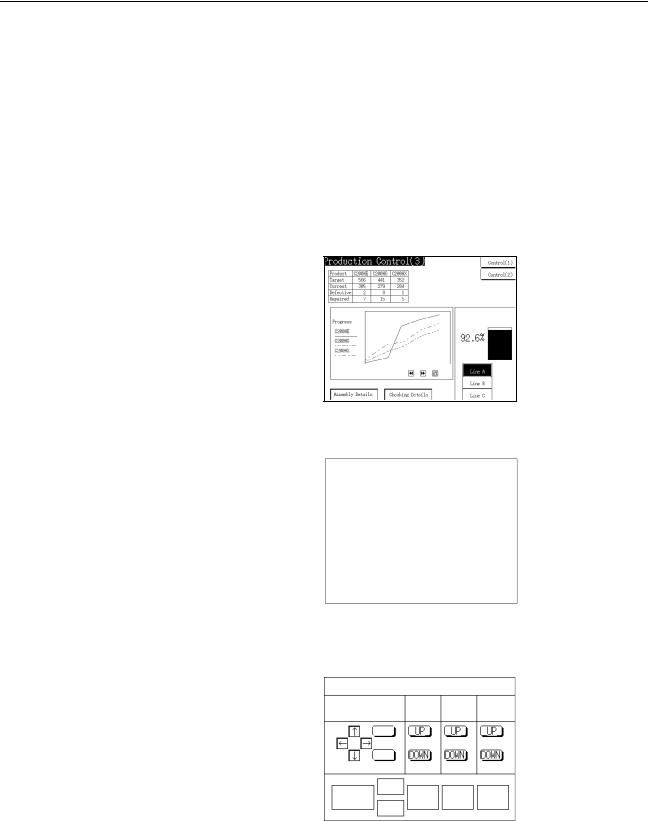
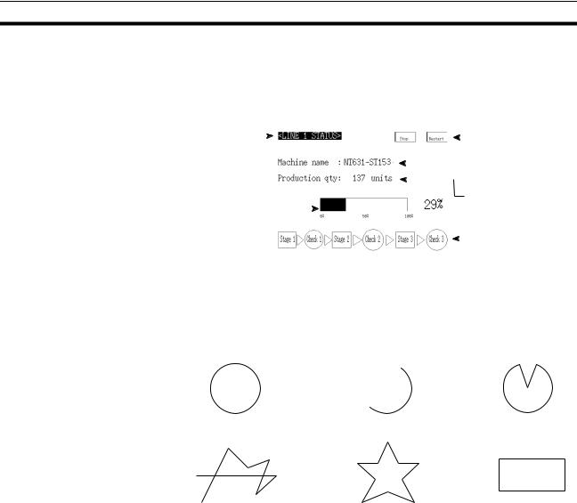
1-1-1 Operation of an NT631/NT631C at an FA Production Site
Production Line Status The NT631/NT631C displays real-time information about the system and Monitoring equipment operating status, etc. Its power of expression is enhanced by
graphs and other visuals, making the displays easy to understand.
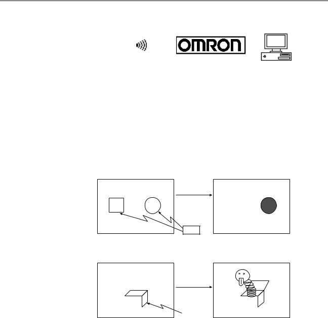
Directions to Workers on |
The NT631/NT631C warns of system or equipment failures and prompts the |
the Shop Floor |
appropriate remedial action. |
|
|
|
|
Alarm |
|
|||
|
|
|
|
|
|
|||
|
|
Assembly line B |
|
|
|
|||
|
|
|
|
|
|
|
||
|
|
Positioning pin |
|
|
|
|
||
|
|
is defective. Line stopped. |
|
|||||
|
|
Check the following. |
|
|
||||
|
1. Defective pin L3 |
|
|
|||||
|
2. Position of dog M2 |
|
|
|||||
|
3. Mounting of photosensor P5 |
|
||||||
Panel Switch Functions |
Setting touch switches on the NT631/NT631C allows workers to use the |
|||||||
|
NT631/NT631C as an operating panel; the results of the operations are trans- |
|||||||
|
mitted to the host. |
|
|
|
|
|
|
|
|
|
|
Electroplating control |
|
||||
|
|
Transport |
Electr. |
Wash. |
Corr. prv. |
|||
|
|
head |
head |
head |
||||
|
|
|
|
|
||||
|
|
|
|
Clamp |
|
|
|
|
|
|
|
Unclamp |
|
|
|
|
|
|
|
|
|
Adv. |
Electro- |
Wash |
Corr. |
|
|
Int. stop |
|
|
|||||
|
|
|
prv.fluid |
|||||
|
|
|
|
Rev. |
lyte |
|
||
|
|
|
|
|
|
|
|
|
2

Role and Operation of the NT631/NT631C Section 1-1
1-1-2 |
Operations of the NT631/NT631C |
|
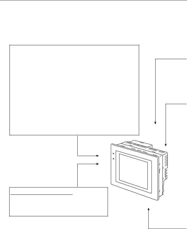
Displays Screens |
The information to be displayed (screen data) can be created on a computer |
|
|
|
using the Support Tool and stored in the NT631/NT631C. The screen data |
|
|
can be displayed on the NT631/NT631C in response to instructions from the |
|
|
host or touch switch operation. |
|
|
Host |
|
|
The screen data designated by |
|
|
instructions from the host or touch |
|
|
switch operation is displayed. |
Receives Data from a Host |
The NT631/NT631C can be connected to the host by a host link or NT link |
|
|
|
and receive necessary data from the host. |
Host Link, NT link
Host
Sends Data to a Host |
Data input using the touch panel (switch ON/OFF statuses, numeric values, |
|
character strings) can be transmitted to the host. |
|
Host |
|
Touch panel |
|
ON/OFF information, numeric |
|
data, etc. |
Screen Data |
The screen data to be displayed on the NT631/NT631C can be created on a |
|
personal computer using the Support Tool. Connect the NT631/NT631C to |
|
the personal computer with an RS-232C cable and transmit the screen data to |
|
the NT631/NT631C. |
|
Create screen data. |
|
RS-232C |
|
|
Personal |
|
|
|
computer |
|
|
(Support Tool) |
|
|
|
|
Screen data
When the host is connected at serial port A, the personal computer is only connected when communicating screen data between the NT631/NT631C and Support Tool.
3
Functions of the NT631/NT631C |
Section 1-2 |
1-2 Functions of the NT631/NT631C
The NT631/NT631C has the following features.
1-2-1 Features
Slim Body
Construction Best Suited to the FA Environment
Touch Switch Operation
Compatibility with Other PTs
•High-performance in a low-profile body (50 mm or less in the panel*).
•The communications cable connectors are housed in the PT so that they do not protrude from the PT.
*When mounted in a panel of the recommended thickness (page 32).
•The display panel is provided with a high-contrast monochrome EL display for the NT631-ST211@-EV2, an STN color LCD display with backlight for the NT631C-ST141@-EV2, and a TFT color LCD high-definition display for NT631C-ST153@-EV3.
•The backlight unit and battery can be replaced at the operation site. (The backlight for the NT631C-ST153@-EV3, however, cannot be replaced by the user.)
•Protection equivalent to oil-proof IP65*, and waterproof structure equivalent to the NEMA4 standard*.
*The panel may not be usable in environments where it is exposed to oil for long periods.
640 dots
POWER
RUN
480 dots
Wide angle of visibility
Contrast and brightness are adjustable by touch switch operations (for NT631C-ST141@-EV2 only).
•There is upward compatibility between the NT631/NT631C and the following models for screen data and user programs: NT11S, NT20S, NT30, NT30C, NT31, NT31 NT600S, NT610G, NT610C, NT620S, NT620C, NT625C. (After being read to the Support Tool, screens must be modified in accordance with the screen size. Depending on the function used, partial modification of programs may also be necessary. For details on the compatibility of screen data, refer to the NT31/NT31C/NT631/NT631C Programmable Terminal Reference Manual and the NT-series Support Tool Operation Manual.
•The dimensions of the panel cut-out to accommodate the NT631/NT631C are the same as for the NT625C.
4

Functions of the NT631/NT631C |
Section 1-2 |
Two Ports Featured as
Standard:
Rapid System Program &
Screen Data Changes
Possible Using a Memory
Unit.
Screen Data Check
Function
Large Increase in
Maximum Number of
Registered Elements
Binary Data can be Read to/Written from the Host
Character Display Using
High Definition Fonts
Simple Version Upgrades
Complies with International Standards
Compatible with Other Vendors’ Devices
Multiple Windows
High-speed 1:N NT Link
Additional Mathematical
Functions
Port A for Common Use by Support Tool/Host and Port B for Exclusive Use by the Host
•Communications with the host is possible via another port while connected to the Support Tool.
•Reading bar code data from a bar code reader is possible via another port while communicating with the host.
•Installing a Memory Unit (type NT-MF261) on the rear of the NT631/ NT631C makes it easy to write screen data into the NT631/NT631C on site. This enables a rapid response to setup changes.
•NT631/NT631C can store a system program into a Memory Unit. This enables the system to handle more flexible setups.
Screen data can be checked simply by operations at the NT631/NT631C system menu, without connecting up to the Support Tool.
The number of elements that can be registered on one screen has been considerably increased, making it possible to create more expressive screens. For details, refer to Display Restrictions in Appendix A Specifications of the NT31/NT31C/NT631/NT631C Programmable Terminal Reference Manual.
It is now possible to write binary data stored in words at the host directly to the NT631/NT631C. This makes data conversion by a program at the host unnecessary, reducing the load on the host.
Any quadrupled characters are displayed with a 32 dot high-definition font.
By using the system installer supplied with the Support Tool (Type NT- ZJCAT1-EV4), the system program at the NT631/NT631C can be changed easily from a personal computer.
The NT631/NT631C meets UL/CSA standards and EC directives.
Compatible with Sequencers in the following series: Mitsubishi A-series (Calculator Link) and FX-series (Programming Console), Allen-Bradley SLC 500 Series, GE Fanuc 90-20 and 90-30 Series, and Siemens S7-300 and S7-400 Series. Specialized system programs can be installed that allow the NT631/ NT631C to be controlled from other companies’ Sequencers.
Up to 3 windows can be displayed simultaneously in the normal screen. A 9- word window control area has been allocated to the host; the contents of these 9 words can be changed from the Host to open, close, and move windows.
The V2 versions are compatible with the high-speed 1:N NT Link as well as the earlier standard 1:N NT Link.
Operands (values referenced by formula) can be registered to allow the PT to perform calculations automatically and write the results of those calculations to numeral memory tables or words in the host.
5

Functions of the NT631/NT631C |
Section 1-2 |
Device Monitor Function
Interlock Function
Improved Lamp/Touch
Switch Labels
NT30/NT30C and NT620S/
NT620C/NT625C
Emulation
Additional CS/CJ-series
Data Areas Accessible
Recipe Function
Adjusting Contrast and
Brightness During PT
Operation
The new device monitor function can be used to change the PLC’s operating mode or display/change values in the PLC’s memory areas. The present values (PVs) of several words can be listed with the device monitor.
PT operations and inputs can be disabled from the PLC if interlock bits have been allocated in the PLC for the corresponding PT touch switches, numeric inputs, or string inputs.
The following displays can be performed with lamp or touch switch labels:
•Display several lines of labels.
•Switch the display between different labels when OFF and ON.
•Display the numeral memory table contents as labels.
•Display the string memory table contents as labels.
The word configuration of the PT status control area and PT status notify area can be set to emulate those of the NT30/NT30C or NT620S/NT620C/ NT625C; this mode is called NT30/620 compatible mode.
When the PT is operating in NT30/620 compatible mode, it will be equivalent to an NT30/NT30C or NT620S/NT620C/NT625C in the functions listed below. The PT retains full V2 functionality in all functions other than the ones listed below. Refer to Appendix C in the NT31/NT31C/NT631/NT631C Programmable Terminal Reference Manual for more details.
•Word configuration and functions of the PT status control area and PT status notify area
•Image/library codes
•Insertion of image/library data into character strings
Data areas in CS/CJ-series PLCs that were previously inaccessible can be accessed. The data areas listed below can be accessed (read/written).
All banks in the EM area, timer completion flags (TU), counter completion flags (CU), Work areas (WR), Task flags (TK), and the HR area.
You can set the data (numeric values) for multiple words in record units using the tabular elements on the PT screen, and write these settings in a single operation to words on the host (i.e., PLC or PT memory) using a touch switch operation on the PT Unit. Also, multiple words of numeric data can be read from the host in one operation. In this way, groups of parameter settings can be edited at the PT Unit, and written to or read from the host.
You can display the brightness and contrast adjustment screen using either the touch switch or commands from the host, even while the PT is in operation.
6

Functions of the NT631/NT631C |
Section 1-2 |
1-2-2 Comparison between NT631 and NT631C
Two NT631 models — the NT631, which is capable of versatile graphic displays (EL display, yellow), and the NT631C, which is also capable of color display — are available. The differences between the NT631 and NT631C are tabled below:
Function |
NT631-ST211@-EV2 |
NT631C-ST141@-EV2 |
NT631C-ST153@-EV3 |
|
|
|
|
Type |
NT631-ST211-EV2 (Beige) |
NT631C-ST141-EV2 (Beige) |
NT631C-ST153-EV3 (Beige) |
|
NT631-ST211B-EV2 (Black) |
NT631C-ST141B-EV2 (Black) |
NT631C-ST153B-EV3 (Black) |
|
|
|
|
Display |
Monochrome EL display |
STN color LCD display |
TFT color LCD display |
panel |
|
(with white backlight) |
(with white backlight) |
|
|
|
|
Beige and black are the front panel colors of each NT631/NT631C types.
7

Functions of the NT631/NT631C Section 1-2
1-2-3 |
Comparison between NT620S/NT620C/NT625C and NT631/ |
|||
|
NT631C |
|
|
|
|
|
|
|
|
|
Item |
NT620S/NT620C/NT625C |
NT631/NT631C |
|
|
|
|
||
Support Tool used |
NT-ZJCAT1-EV4 or NT-ZA3AT-EV2 |
NT-ZJCAT1-EV4 |
||
|
|
|
||
DIP switches |
On rear of PT |
None (software settings) |
||
|
|
|
||
Use of Memory Unit |
Not possible |
Possible |
||
|
|
|
||
RS-232C interface |
Connector (9-pin) also used as port for |
- Serial port A connector (also used for screen |
||
|
|
screen data transfer. |
data transfer, 9-pin) |
|
|
|
|
- Serial port B connector (for host communica- |
|
|
|
|
tions only, 9-pin) |
|
|
|
|
||
RS-422A/485 interface |
NT620S/NT620C: None |
Terminal block (serial port B; memory-switch |
||
|
|
NT625C: Terminal block (DIP-switch |
selectable between RS232C and RS-422A/485) |
|
|
|
|
||
|
|
selectable between RS232C and RS- |
|
|
|
|
422A/485) |
|
|
|
|
|
||
Replacement backlight |
NT620C-CFL01 (NT620C) |
NT631C-CFL01 (for ST151; the backlight for the |
||
|
|
NT610C-CFL02 (NT625C) |
NT631C-ST152@-EV2, NT631C-ST153@-EV3, |
|
|
|
|
however, cannot be replaced by the user) |
|
|
|
|
NT631C-CFL02 (for ST141) |
|
|
|
|
||
NT631/NT631C system pro- |
NT620-ZS3AT-EV1/EMV1 |
The system installer and system program data |
||
gram data |
|
(including system installer) |
are supplied with the Support Tool. |
|
|
|
|
||
High-speed 1:N NT Link |
Not possible |
Possible |
||
|
|
|
|
|
Memory |
System program |
Exclusive use by Memory Link |
Same as OMRON connection |
|
Link |
|
|
|
|
Screen data |
Shared with OMRON connection |
Exclusive use by Memory Link |
||
|
||||
|
|
|
|
|
LCD contrast adjustment |
By a control on the rear of the PT |
By touch panel operation |
||
|
|
|
(Possible in the NT631-ST141@-V2 only.) |
|
Backlight brightness adjust- |
Not possible |
By touch panel operation |
||
ment |
|
|
(Possible in the NT631-ST141@-V2 only.) |
|
Number of user-registered |
Maximum of 2000 |
Maximum of 3999 |
||
screens |
|
|
|
|
|
|
|
||
Screen data capacity*1 |
NT620S: 512 KB |
1 MB |
||
(User program memory) |
NT620C/NT625C: 1 MB |
|
||
|
|
|||
|
|
|
||
Numeral string data |
Maximum of 1000 |
Maximum of 2000 |
||
|
|
|
||
Character string data |
Maximum of 1000 |
Maximum of 2000 |
||
|
|
|
|
|
Bit data |
|
256 |
Maximum of 1000 |
|
|
|
|
||
Mathematical tables |
None |
256 max. |
||
|
|
|
Calculations can be executed automatically in |
|
|
|
|
the PT. |
|
|
|
|
|
|
Image data |
|
Maximum of 224 |
Maximum of 4095*2 |
|
Library data |
Maximum of 896 |
Maximum of 12288*2 |
||
Method for storing numeric |
Fixed as BCD (binary coded decimal) |
Selectable from BCD (binary coded decimal) or |
||
values |
|
|
binary |
|
(numeral memory data and PT |
|
|
||
status control area) |
|
|
||
|
|
|
||
PT status control area size |
4 words |
5 words (partial change of contents)*2 |
||
PT status notify area size |
3 words |
2 words (partial change of contents)*2 |
||
Window control area size |
None |
9 CH |
||
|
|
|
||
Registering continuous screen |
Possible |
Not possible (Use a screen switchover as a sub- |
||
|
|
|
stitute.) |
|
|
|
|
||
Lamp/Touch switch labels |
Fixed display (1 line only) |
- Multiple lines can be displayed |
||
|
|
|
- ON/OFF switching is possible |
|
|
|
|
- Numeral display is possible |
|
|
|
|
- Character string display is possible |
|
8

Functions of the NT631/NT631C |
Section 1-2 |
|
|
|
|
Item |
NT620S/NT620C/NT625C |
NT631/NT631C |
|
|
|
Interlock function |
None |
Operations can be disabled from the PLC by |
|
|
allocating interlock bits to the corresponding |
|
|
touch switch, numeral input, or character string |
|
|
input. |
|
|
|
Device monitor function |
Not possible |
Possible |
|
|
|
Recipe function |
None |
Possible |
|
|
|
Accessible CS/CJ-series PLC |
--- |
The data areas listed below can be accessed in |
data areas |
|
addition to the data areas accessible with the |
|
|
NT30/NT30C. |
|
|
- EM banks (EM_0 to EM_C) |
|
|
- Timer completion flags (TU) |
|
|
- Counter completion flags (CU) |
|
|
- Work areas (WR) |
|
|
- Task flags (TK) |
|
|
- HR area |
|
|
|
*1 This is the capacity of the flash memory that stores screen data.
*2 The values are the same as the NT30/NT30C when the PT is in NT30/620 compatible mode.
For differences in programming, refer to Appendix B in the NT31/NT31C/NT631/NT631C Programmable Terminal Reference Manual.
9
Functions of the NT631/NT631C |
Section 1-2 |
1-2-4 Principal Functions of NT631/NT631C
The following are the principal functions of the NT631/NT631C.
Functions relating to data display
Character display
Characters of various sizes can be displayed. Characters can be flashed and displayed in reverse video. High grade fonts are available for the characters with their size enlarged.
Graphic display
Polylines, rectangles, polygons, circles, circular arcs, and sector shapes can be displayed.
They can also be tiled with various patterns, flashed, or displayed in reverse video.
Memory data display
The contents of character string memory tables and numeral memory tables can be displayed.
The contents of memory tables can be changed from the host.
Graph display
Not only bar graphs but also broken line graphs, trend graphs, and analogue meter graphs can be displayed using numeral memory tables
Lamp display
Lamps can be turned on and flashed under the control of the host. It is also possible to display different graphics in the ON and OFF states.
Alarm list/history display
Warning messages are automatically displayed in a list in response to the state of a host bit. The time and the number of times of the messages appeared can also be displayed.
Functions relating to data output
Buzzer
A built-in buzzer can be sounded.
Screen printing
A hard copy of the currently displayed screen can be printed at the printer connected to the NT631/NT631C.
10

Functions of the NT631/NT631C |
Section 1-2 |
Functions relating to data input
Input by touch switches
Data can be input by simply touching touch switches displayed on the screen.
The possible functions of touch switches include sending data to the host and changing the screen display.
Inputs can be enabled and disabled from the host when interlock bits have been allocated.
Pop-up window function
A window overlaying the currently displayed screen can be alternately opened and closed by pressing a touch switch.In addition to fixed character and graphic displays, control keys and character keys created as touch switches can also be set inside the window.
A maximum of three windows can be displayed simultaneously.
Since the window need only be opened when input is required, the screen can be used efficiently.
Numeral/character string setting function
Numeric keys and character keys can be assigned to touch switches so that numeric values and character strings can be input at the operation site.
The input data is written to numeral/character string memory tables and also sent to the host. It is also possible to disable input by control from the host.
Recipe function
Several words of numeric data can be edited at the PT Unit, and written to or read from the host in one operation.
Input from a bar code reader
Data read with a bar code reader can be input to a character string input field.
Functions relating to communications
Communications with the host
The NT631/NT631C can communicate with the host by four methods: host link, 1:1 NT link, 1:N NT link (standard or high-speed), and Memory link. Data can be read from the host, and data input by means of touch switches and numeral/character string settings can be sent to the host. It is also possible to connect with other model PCs.
Functions relating to the system
System menu
System settings and maintenance can be performed by selecting from system menus displayed on the screen.
Creation of screen data
Screen data created using the Support Tool at a personal computer can be transferred and stored in the built-in screen data memory.
Resume function
The status and memory table contents of the NT631/NT631C immediately before its operation is stopped can be stored while operation is stopped, or while the power is off, and then displayed on the screen again when operation is restarted.
Screen saver function
This function serves to extend the service life of the backlight and EL and prevent the formation of an afterimage on the screen.
Clock function
The time can be displayed in accordance with the internal clock data.
Programming Console function
When the NT631/NT631C is connected to a C-series CPM1, CPM2A, CPM2C, CQM1, CQM1H, or C200HX/HG/ HE(-Z)E Programmable Controller in an NT link (1:1) connection, or is connected to CS/CJ-series in an NT link (1:N) connection, operations equivalent to those of a Programming Console (C200H-PR027-E) are possible.
Device Monitor function
When the PT is connected to a PLC in a 1:1 NT Link or 1:N NT Link, the PT can be used for operations such as changing the PLC's operating mode, displaying or changing the PVs of words, or reading the error log.
System program install function
The system program of the NT631/NT631C can be changed by using the system installer supplied with the Support Tool (NT-ZJ3AT1/ZJCAT-EV2). It can also be installed by using a memory unit (NT-MF261).
Screen display history function/alarm history function
The screen display history function records the time at which specific screens are displayed and the number of times they are displayed. The alarm history function records the time at which specific bits at the host are turned ON and the number of times they are turned ON.
Trend graph logging function and background function
Changes in the contents of numeral memory tables displayed in trend graphs can be recorded (logging function). Also, the record can be maintained even when the trend graph is not displayed (background function).
Mathematical function
This function allows calculations to be executed continuously during PT operation when mathematical table have been set in screen data. Arithmetic operations, bit operations, logic operations, and comparison operations can be performed. Operations with up to 5 terms are possible.
11
Functions of the NT631/NT631C Section 1-2
1-2-5 |
Displays |
|
|
|
|
|
|
|
|
|
|
|
|
|
|
|
|
The NT631/NT631C can display various kinds of elements such as charac- |
|||||||||||||
|
|
ters, numeric values, graphs, lamps, and touch switches, on a screen. The |
|||||||||||||
|
|
screen data displayed by the NT631/NT631C are created by using the Sup- |
|||||||||||||
|
|
port Tool at a personal computer. |
|
|
|
|
|
|
|||||||
|
|
Characters |
|
|
|
|
|
|
|
|
|
|
|
|
Touch switches |
|
|
(fixed display) |
|
|
|
|
|
|
|
|
|
|
|
||
|
|
|
|
|
|
|
|
|
|
|
|
|
Characters |
||
|
|
|
|
|
|
|
|
|
|
|
|
|
|||
|
|
|
|
|
|
|
|
|
|
|
|
|
(character string display) |
||
|
|
|
|
|
|
|
|
|
|
|
|
|
Numeric values |
||
|
|
Bar graph |
|
|
|
|
|
|
|
|
|
(numeral display) |
|||
|
|
|
|
|
|
|
|
|
|||||||
Fixed Displays |
|
|
|
|
|
|
|
|
|
|
|
|
|
Lamps |
|
|
|
|
|
|
|
|
|
|
|
|
|
||||
|
|
|
|
|
|
|
|
|
|
|
|
|
|
||
Characters and |
various graphics (circles, circular |
arcs, sectors, polylines, |
|||||||||||||
|
|
polygons and rectangles) whose display does not have to be changed, and |
|||||||||||||
|
|
mark data, image data, and library data that has already been registered, can |
|||||||||||||
|
|
be written directly onto the screen. |
|
|
|
|
|
|
|||||||
|
|
Circle |
|
|
|
Arc |
|
|
|
Sector |
|||||
Polyline |
Polygon |
Rectangle |
*A continuous straight line with up to 256 points can be drawn.
*A polygon with up to 255 vertices can be drawn.
Marks are graphics comprising 16 by 16 dots that can be used as characters. They can be used as custom characters within character strings.
Image data are graphics comprising any required area of dots. They are registered in advance and as many as required can be displayed at any position on the screen.
Windows bit map (BMP) data can be used for images.
There is a two-color mode, in which the display color and background color of the image are specified when it is registered in a screen, and an eight-color mode in which colors are assigned to the image in advance.
Since image data is composed of dots, it requires a large data size but offers great powers of expression.
Library data are combinations of fixed display graphics registered as a single graphic. They are registered in advance and as many as required can be displayed at any position on the screen.
Since it is generated by combining graphics, library data has a small data size.
12
Functions of the NT631/NT631C |
|
Section 1-2 |
Mark |
Image data |
Library data |
Lamps |
These are graphics whose display status changes in accordance with the |
||
|
states of bits at the host. Squares, circles, sectors and polygons can be used |
||
|
for lamps (normal (standard) lamps). In accordance with the status of the host |
||
|
bit, they can be lit (displayed in reverse video) or flashed (repeated alternation |
||
|
between normal and reverse video display states). |
||
|
Lamps can also display different image/library data for the ON and OFF states |
||
|
of the host bit (such lamps are called image/library lamps). |
||
|
There are four standard lamp labels: fixed display character strings, ON/OFF |
||
|
switching character strings, numeral displays, and character string displays. |
||
|
When fixed display character strings or ON/OFF switching character strings |
||
|
are used, several lines of labels can be displayed. |
||
|
Normal (Standard) Lamps |
||
|
|
|
|
|
|
|
|
ON
ON Host
Unlit state |
Lit state |
Image/Library Lamps
|
|
|
|
ON |
|
|
|
|
|
|
|
|
|
|
|
|
|
|
|
|
|
Host |
|
|
|
|
|
|
|
|
|
|
|||
|
Unlit state |
|
|
|
Lit state |
|||
Touch Switches |
These switches can be set at any location on the screen. Pressing a touch |
|||||||
|
switch on the screen where a touch switch has been set can have the follow- |
|||||||
|
ing effects: |
|
|
|
|
|
||
Notification to a host bit (input notification function)
Changing the displayed screen (screen switching function)
Input of a numeric value or character string (input key function)
Copying of a numeric value or character string (copy key function)
Shifting to another numeric value or character string input field (cursor moving key function)
Obtaining a hard copy of the screen (screen print function)
Opening / Closing a window
Moving a window
Touch switches can be made to light or flash in accordance with the status of a host bit in the same way as lamps.
The following 8 types of display graphic can be used for touch switches:
13
Loading...