


3G3RV-P10ST@-E
G7/F7/L7/E7 inverter PLC
The OMRON PLC technology embedded in the OMRON Yaskawa inverter family
•OMRON PLC programmability in the OMRON Yaskawa inverters.
•Flexibility and intelligence in the OMRON Yaskawa inverter family.
•Wireless installation and seamless access to the inverter parameters and analogue/digital inputs and outputs.
•OMRON Compobus/S fieldbus inside. Thus, able to control up to 256I/O's.
•Easy to integrate in the automation world: DeviceNet type available.
•Standard OMRON tools can be used for programming and commissioning.
•Ideal for applications like:
•Pump sequencing, remote control, water treatment,etc together with the HVAC inverter: E7&E7 IP54.
•Lift as control sequence inside, using the lift inverter: L7.
•Cranes, winding/rewinding, position control, others combined with the powerful flux vector control inverter: F7Z.
•General purpouse using the high technology of G7 3-Level vector control.
System configuration
RS-232C CX-One (CX-Drive)
(CX-Programmer)
HMI interface
RS-422
Other serial devices
DeviceNet
Varispeed + PLC
CompoBus/S communication path
Terminator
16 of 32 slaves max.
G7/F7/L7/E7 inverter PLC |
365 |

Type designation
PLC inverter
3G3RV-P10ST8-DRT-E
|
|
|
|
|
|
|
|
|
|
|
|
|
|
|
|
|
|
|
|
|
Inverter series |
|
|
|
|
|
|
|
|
|
|
|
|
|
|
|
|
DeviceNet slave |
|
||
Number of I/O's |
|
|
|
|
|
|
|
Options |
- |
No |
|
|
||||||||
|
|
|
|
|
|
|
|
|||||||||||||
|
|
|
|
|
|
|
|
|
|
|
|
|
|
|
DRT |
Yes |
|
|
||
|
|
|
|
|
|
|
|
|
|
|
|
|
|
|
|
|
|
|
||
|
|
|
|
|
|
|
|
|
|
|
|
|
|
|
|
|
|
|||
|
|
|
|
|
|
|
|
|
|
|
Output |
|
RTC |
|
RS422 |
Remarks |
||||
|
|
|
|
|
|
|
|
- |
|
|
NPN |
|
NO |
|
NO |
|
|
|||
|
|
|
|
|
|
|
|
|
|
|
|
|
|
|
|
|||||
|
|
|
|
|
|
|
|
1 |
|
|
NPN |
|
NO |
|
YES |
|
|
|||
|
|
|
|
|
|
|
|
2 |
|
|
NPN |
|
YES |
|
NO |
|
|
|||
|
|
|
|
|
|
|
|
3 |
|
|
NPN |
|
YES |
|
YES |
|
|
|||
|
|
|
|
|
|
|
|
|
|
|
|
|
|
|
|
|||||
|
|
|
|
|
|
|
|
5 |
|
|
PNP |
|
NO |
|
NO |
|
|
|||
|
|
|
|
|
|
|
|
6 |
|
|
PNP |
|
NO |
|
YES |
|
|
|||
|
|
|
|
|
|
|
|
7 |
|
|
PNP |
|
YES |
|
NO |
|
|
|||
|
|
|
|
|
|
|
|
|
|
|
|
|
|
|
||||||
|
|
|
|
|
|
|
|
8 |
|
|
PNP |
|
YES |
|
YES |
Standard |
||||
Specifications
Specifications by product
Item |
3G3RV-P10ST8-E |
3G3RV-P10ST8-DRT-E |
PLC core |
CPM2C-S |
CPM2C-S |
|
|
|
Inputs |
6 24 VDC inputs |
6 24 VDC inputs |
|
|
|
Outputs |
4 sourcing/PNP transistor outputs |
4 sourcing/PNP transistor outputs |
Peripheral port |
Yes |
Yes |
|
|
|
RS-232C port |
Yes |
Yes |
|
|
|
RS-422 port |
No |
Yes |
Calendar/clock |
Yes |
Yes |
|
|
|
Memory backup |
Flash memory and battery |
Flash memory and battery |
|
|
|
Compobus/S master interface |
Yes |
Yes |
Encoder interface |
Yes |
Yes |
|
|
|
DeviceNet Slave interface |
No |
Yes |
|
|
|
General specifications
Item |
|
Specifications |
|
|
|
3G3RV-P10ST8-E |
3G3RV-P10ST8-DRT-E |
Rated power supply voltage |
24 VDC +10%/-15% (external power supply for I/O) |
|
|
Communications power supply voltage |
--- |
11 to 25 VDC (supplied by communications connector) |
|
|
|
|
|
Power consumption |
Internal power |
2 W (supplied internally) (see note) |
3 W (supplied internally) (see note) |
supply |
Communications power supply |
--- |
30 mA max. |
|
|
|
|
Vibration resistance |
|
10 to 20 Hz, 9.8 m/s2 max. |
|
|
|
20 to 50 Hz, 2 m/s2 max |
|
Ambient operating temperature |
-10 to 45 °C |
|
|
|
|
|
|
Ambient operating relative humidity |
10% to 90% (no condensation) |
|
|
|
|
|
|
Ambient storage temperature |
-20 to 70 °C |
|
|
Atmosphere |
|
Must be free from corrosive gas |
|
|
|
|
|
Control method |
|
Store program method |
|
|
|
|
|
I/O control method |
|
Cyclic scan method |
|
Programming language |
Ladder chart method |
|
|
|
|
|
|
Instruction length |
|
1 step/1 instruction; 1 to 5 words/1 instruction |
|
|
|
|
|
Instruction types |
Basic |
14 types (same as for programmable slaves) |
|
|
Special |
105 types, 185 instructions (same as for programmable slaves) |
|
|
|
|
|
Processing speed |
Basic instructions |
0.64 µs (LD) |
|
|
|
|
|
|
Special instructions |
7.8 µs (MOV) |
|
Program capacity |
|
4,096 words |
|
|
|
|
|
Maximum number of I/O points |
10 |
|
|
|
|
|
|
Input bits |
|
00000 to 00015 (6 physical inputs) |
|
Output bits |
|
01000 to 01003 (4 physical outputs) |
|
|
|
||
CompoBus/S input bits |
128 bits: IR 02000 to IR 02715 (bits not used for CompoBus/S input bits can be used for work bits.) |
||
|
|
||
CompoBus/S output bits |
128 bits: IR 03000 to IR 03715 (bits not used for CompoBus/S output bits can be used for work bits.) |
||
Inverter interface |
|
Direct interface with inverter through |
|
|
|
• IR-memory |
|
|
|
• DM-memory |
|
|
|
• Transfer command |
|
|
|
|
|
Inverter interface bits |
|
176 bits: IR 20000 to IR 21015 |
|
|
|
|
|
Encoder interface bits |
|
48 bits: IR 02900 to IR 02915 and IR 04800 to IR 04915 |
|
Work bits |
|
448 bits: IR 02800 to IR 02815, IR 03800 to IR 04715, and IR 21100 to IR 22715 |
|
|
|
|
|
Special bits (SR area) |
|
448 bits: SR 22800 to SR 25507 (words SR 228 to SR 255) |
|
|
|
|
|
Temporary bits (TR area) |
8 bits (TR 0 to TR 7) |
|
|
Holding bits (HR area) |
|
320 bits: HR 0000 to HR 1915 (words HR 00 to 19) |
|
|
|
|
|
Auxiliary bits (AR area) |
384 bits: AR 0000 AR 2315 (words AR 00 to AR 23) |
|
|
|
|
|
|
366 |
3G3RV-P10ST@-E |

Item |
|
Specifications |
|
|
|
3G3RV-P10ST8-E |
3G3RV-P10ST8-DRT-E |
Link bits (LR area) |
|
256 bits: LR 0000 to LR 1515 (words LR 00 to LR 15) |
|
Timers/counters |
|
256 timers/counters (TIM/CNT 000 to TIM/CNT) |
|
|
|
1-ms timers: TMHH(--) |
|
|
|
10-ms timers: TIMH(15) |
|
|
|
100-ms timers: TIM |
|
|
|
1-s/10-s timers: TIML(--) |
|
|
|
Decrementing counters: CNT |
|
|
|
Reversible counters: CNTR(12) |
|
|
|
||
CompoBus/S master functions |
Remote I/O devices can be allocated up to 256 I/O points (128 inputs and 128 outputs) in input area IR 020 to |
||
|
|
IR 027 and output area IR 030 to IR 037. |
|
|
|
• The node numbers can be set to 0 to 7 (128-point mode) or 0 to 15 (256-point mode). |
|
|
|
• The communications mode can be set to high-speed mode (max. length 100 m) or long-distance mode |
|
|
|
(max. length 500 m). |
|
DeviceNet slave functions |
Up to 64 words (32 input words and 32 output words) can be allocated to the DeviceNet master's I/O. |
||
|
|
The master's I/O can be allocated to the following data areas: |
|
|
|
IR 000 to IR 049 |
|
|
|
IR 200 to IR 227 |
|
|
|
DM 0000 to DM 2047 |
|
|
|
LR 00 to LR 15 |
|
|
|
HR 00 to HR 19 |
|
|
|
AR 00 to AR 23 (3G3RV-P10ST ' master; read-only) |
|
|
|
TC 000 to TC 255 |
|
|
|
• Explicit message communications are supported. Any 3G3RV-P10ST data area can be accessed from the |
|
|
|
DeviceNet master. |
|
|
|
• The communications speed can be set to 500 kbps (total network length 100 m max.), 250 kbps (total network |
|
|
|
length 250 m max.), or 125 kbps (total network length 500 m max.). |
|
|
|
|
|
DM area |
Read/write |
2,029 words (DM 0000 to DM 0999, DM 1019 to DM 2047) |
|
|
|
DM 2000 to DM 2021: error log storage area |
|
|
Read only |
456 words (DM6144 to 6599) |
|
|
|
|
|
|
Inverter interface |
19 words (DM 2022 to DM 2040) |
|
|
Encoder interface |
14 words (DM 1986 to DM 1999) |
|
|
PLC setup |
56 words (DM 6599 to DM 6655) |
|
|
|
|
|
Interrupts |
|
Interrupt inputs |
|
|
|
2 inputs |
|
|
|
Response time: 50 µs |
|
|
|
|
|
|
|
Interval timer interrupts |
Scheduled interrupts |
|
|
1 input |
|
|
|
Set value: 0.5 to 319,968 ms |
One-shot interrupt |
|
|
Precision: 0.1 ms |
|
High-speed counters |
High-speed counter 1 input, |
No interrupt |
|
|
see note 5 |
|
|
|
Differential phase mode (5 kHz) |
Count-check interrupt |
|
|
Pulse plus direction input mode |
(An interrupt can be generated when the count equals the set value or the count lies within a preset range.) |
|
|
(20 kHz) |
|
|
|
Up/down input mode (20 kHz) |
|
|
|
Increment mode (20 kHz) |
|
|
|
|
|
|
|
Interrupt inputs (counter mode) |
No interrupt |
|
|
2 inputs |
Count-up interrupt |
|
|
Incrementing counter (2 kHz) |
|
|
|
Decrementing counter (2 kHz) |
|
|
Encoder interface |
|
3 input modes: |
|
|
|
Differential-phase (up/down) |
|
|
|
Pulse plus direction |
|
|
|
Up/down pulse |
|
|
|
Maximum input frequency 50 kHz |
|
|
|
Maximum counter range 4,294,967,295 (232-1) |
|
|
|
Two capture registers, 3 selectable registration inputs |
|
|
|
One comparison value |
|
|
|
Counter reset through software or Z-phase |
|
|
|
Interrupt function |
|
Pulse outputs |
|
• 2 outputs: |
|
|
|
Single-phase pulse output without acceleration/deceleration (see note 6.) |
|
|
|
10 Hz to 10 kHz |
|
|
|
• 2 outputs: |
|
|
|
Variable duty ratio pulse output (see note 6.) |
|
|
|
0.1 to 999.9 Hz, duty ratio 0 to 100% |
|
|
|
• 1 output: |
|
|
|
Pulse output with trapezoidal acceleration/deceleration (see note 6.) |
|
|
|
Pulse plus direction output, up/down pulse output, 10 Hz to 10 kHz |
|
Synchronized pulse control |
1 point, see notes 5 and 6 |
|
|
|
|
Input frequency range: 10 to 500 Hz, 20 Hz to 1 kHz, or 300 Hz to 20 kHz |
|
|
|
Output frequency range: 10 Hz to 10 kHz |
|
Pulse catch inputs |
|
2 bits |
|
|
|
Minimum pulse input: 50 µs max. |
|
|
|
Used in common by input interrupts and input interrupt counter mode. |
|
Analog volume |
|
None |
|
|
|
|
|
Input time constant |
|
Determines the input time constant for all inputs. (settings: 1, 2, 3, 5, 10, 20, 40, or 80 ms) |
|
(ON response time = OFF response time) |
|
|
|
Clock/Calendar function |
Shows the current year, month, day of the week, day of the month, hour, minute, and second. |
||
|
|
|
|
Communication function |
Port 1 = Peripheral and RS-422: |
|
|
|
|
Host link, peripheral bus, no-protocol, programming console |
|
|
|
Port 2 = RS-232C port: |
|
|
|
Host link, no-protocol, 1:1 PLC link, 1:1 NT link |
|
G7/F7/L7/E7 inverter PLC |
367 |
Item |
|
Specifications |
|
|
|
3G3RV-P10ST8-E |
3G3RV-P10ST8-DRT-E |
Power-interruption hold function |
Holds the contents of HR, AR, CNT, and DM areas. |
|
|
Memory backup (see notes 1 and 2.) |
Flash memory: Program, read-only DM area, and PC setup |
||
|
|
Memory backup: The read/write DM area, HR area, AR area, and counter values are backed up. |
|
|
|
(The battery has a 5-year lifetime at 25 °C and it is replaceable.) |
|
Self-diagnostic function |
CPU errors, memory errors, communications errors, setting errors, battery errors |
||
|
|
|
|
Program check |
|
No END instruction, program errors (regularly checked during operation) |
|
Connected tools |
CX-programmer |
After version 2.1 |
|
|
Programming console |
C200H-PRO27, CQM1-PRO01 |
|
|
|
|
|
|
SSS |
PC98 & PC/AT (SYSMAC support software, all versions) |
|
|
CX-drive |
Version 1 or higher |
|
Note: 1. The DM area, HR area, AR area, and counter values are backed up. If the backup battery or capacitor is discharged, the contents of these areas will be lost and the data values will revert to the defaults.
2.The contents of the program area, read-only DM area (DM6144 to DM6599), and PLC setup (DM 6600 to DM 6655) are stored in flash memory. The contents of these areas will be read from flash memory the next time the power is turned ON, even if the backup battery or capacitor is discharged.
When data has been changed in any of these areas, write the new values to flash memory by switching the 3G3RV-P10ST to MONITOR or RUN mode, or by turning the power OFF and then ON again.
3.Changes made while in MONITOR mode using, for example, online editing, are written to flash memory in real-time.
4.The above figure for power consumption includes the power consumption of the programming console.
5.This input is shared by the high-speed counter and synchronized pulse control functions.
6.This output is shared by the pulse output and synchronized pulse control functions.
I/O specifications
Input specifications
Item |
Inputs |
Specification |
|
|
|
|
|
|
|
|||||
Input voltage |
All |
24 VDC +10%/ |
|
|
|
|
|
|
|
|||||
|
|
-15% |
|
|
|
|
|
|
|
|
|
|
|
|
Input impedance |
IN 00000 to IN 00001 |
2.7 kΩ |
|
|
|
|
|
|
|
|||||
|
IN 00002 to IN 00004 |
3.9 kΩ |
|
|
|
|
|
|
|
|||||
|
IN 00005 |
4.7 kΩ |
|
|
|
|
|
|
|
|||||
Input current |
IN 00000 to IN 00001 |
8 mA typical |
|
|
|
|
|
|
|
|||||
|
|
|
|
|
|
|
|
|
|
|
|
|
|
|
|
IN 00002 to IN 00004 |
6 mA typical |
|
|
|
|
|
|
|
|||||
|
IN 00005 |
5 mA typical |
|
|
|
|
|
|
|
|||||
ON voltage/current |
IN 00000 to IN 00001 |
17 VDC min., 5 mA |
|
|
|
|
|
|
|
|||||
|
|
|
|
|
|
|
|
|
|
|
|
|
|
|
|
IN 00002 to IN 00005 |
14.4 VDC min., 3.5 mA |
|
|
|
|
|
|
|
|||||
OFF voltage/current |
All |
5.0 VDC max., 1.1 mA |
|
|
|
|
|
|
|
|||||
ON delay |
All |
1 to 80 ms max. Default: 10 ms (see note.) |
|
|
|
|
|
|
|
|||||
|
|
|
|
|
|
|
|
|
|
|
|
|
|
|
OFF delay |
All |
1 to 80 ms max. Default: 10 ms (see note.) |
|
|
|
|
|
|
|
|||||
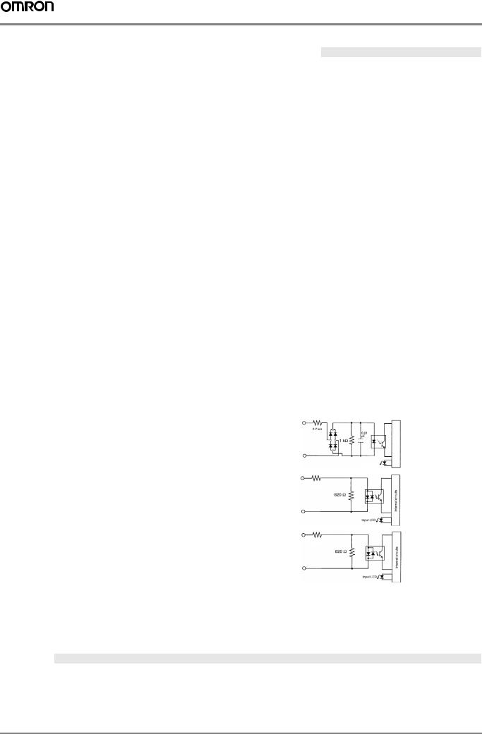
Circuit configuration |
IN 00000 to IN 00001 |
IN |
|
|
|
|
|
|
|
|||||
|
|
|
|
|
|
|
|
|
|
|
|
|
|
|
|
|
|
2.7 kΩ |
|
|
|
|
|
|
|
||||
|
|
|
|
|
|
|
|
|
0.01 |
|
|
|
circuitsInternal |
|
|
|
|
|
|
|
|
|
|
µF |
|
|
|
||
|
|
|
|
|
|
1kΩ |
|
|
|
|
|
|
|
|
|
|
COM |
|
|
|
|
|
|
|
|||||
|
|
|
|
|
|
|
|
|
Input LED |
|
|
|
||
|
|
|
|
|
|
|
|
|
|
|
|
|
|
|
|
IN 00002 to IN 00004 |
IN |
|
|
|
|
|
|
|
|||||
|
|
|
|
|
|
|
|
|
||||||
|
|
|
3.9 kΩ |
|
|
|
|
|
|
|
|
|
|
|
|
|
|
|
|
|
|
|
|
|
|
|
|
|
|
|
|
|
|
|
|
|
|
|
|
|
|
|
circuitsInternal |
|
|
|
|
|
|
820 Ω |
|
|
|
|
|
||||
|
|
COM |
|
|
|
|
|
|
|
|||||
|
|
|
|
|
|
|
|
|
|
|
|
|
|
|
|
|
|
|
|
|
|
|
|
Input LED |
|
|
|
||
|
|
|
|
|
|
|
|
|
|
|
|
|
|
|
|
IN 00005 |
IN |
|
|
|
|
|
|
|
|||||
|
|
|
4.7 kΩ |
|
|
|
|
|
|
|
|
|
||
|
|
|
|
|
|
|
|
|
|
|
|
|
|
|
|
|
|
|
|
|
|
|
|
|
|
|
|
circuitsInternal |
|
|
|
|
|
|
750 Ω |
|
|
|
|
|
|
|||
|
|
COM |
|
|
|
|
|
|
|
|||||
|
|
|
|
|
|
|
|
|
|
|
|
|
|
|
|
|
|
|
|
|
|
|
|
Input LED |
|
|
|
||
|
|
|
|
|
|
|
|
|
|
|
|
|
|
|
Note: The input time constant can be set to 1, 2, 3, 5, 10, 20, 40, or 80 ms in the PLC setup.
High-speed counter inputs
The following unit input bits can be used as high-speed counter inputs. The maximum count frequency is 5 kHz in differential phase mode and 20 kHz in the other modes.
Input |
Function |
|
|
|
|
Differential phase mode |
Pulse plus direction input mode |
Up/down input mode |
Increment mode |
IN 00000 |
A-phase pulse input |
Pulse input |
Increment pulse input |
Increment pulse input |
IN 00001 |
B-phase pulse input |
Direction input |
Decrement pulse input |
Normal input |
|
|
|
|
|
IN 00002 |
Z-phase pulse input or hardware reset input (IN00002 can be used as a normal input when it is not used as a high-speed counter input.) |
|||
368 |
3G3RV-P10ST@-E |
 Loading...