


 Loading...
Cat. No. W420-E1-04
SYSMAC CS and CJ Series
CS1W-ETN21 (100Base-TX)
CJ1W-ETN21 (100Base-TX)
Ethernet Units
Construction of Networks
OPERATION MANUAL
CS1W-ETN21 (100Base-TX)
CJ1W-ETN21 (100Base-TX)
Ethernet Units
Construction of Networks
Operation Manual
Revised January 2006
iv
Notice:
OMRON products are manufactured for use according to proper procedures by a qualified operator and only for the purposes described in this manual.
The following conventions are used to indicate and classify precautions in this manual. Always heed the information provided with them. Failure to heed precautions can result in injury to people or damage to property.
!DANGER Indicates an imminently hazardous situation which, if not avoided, will result in death or serious injury. Additionally, there may be severe property damage.
!WARNING Indicates a potentially hazardous situation which, if not avoided, could result in death or serious injury. Additionally, there may be severe property damage.
!Caution Indicates a potentially hazardous situation which, if not avoided, may result in minor or moderate injury, or property damage.
OMRON Product References
All OMRON products are capitalized in this manual. The word “Unit” is also capitalized when it refers to an OMRON product, regardless of whether or not it appears in the proper name of the product.
The abbreviation “Ch,” which appears in some displays and on some OMRON products, often means “word” and is abbreviated “Wd” in documentation in this sense.
The abbreviation “PLC” means Programmable Controller. “PC” is used, however, in some Programming Device displays to mean Programmable Controller.
Visual Aids
The following headings appear in the left column of the manual to help you locate different types of information.
Note Indicates information of particular interest for efficient and convenient operation of the product.
1,2,3... 1. Indicates lists of one sort or another, such as procedures, checklists, etc.
OMRON, 2003
All rights reserved. No part of this publication may be reproduced, stored in a retrieval system, or transmitted, in any form, or by any means, mechanical, electronic, photocopying, recording, or otherwise, without the prior written permission of OMRON.
No patent liability is assumed with respect to the use of the information contained herein. Moreover, because OMRON is constantly striving to improve its high-quality products, the information contained in this manual is subject to change without notice. Every precaution has been taken in the preparation of this manual. Nevertheless, OMRON assumes no responsibility for errors or omissions. Neither is any liability assumed for damages resulting from the use of the information contained in this publication.
v
Unit Versions of CS/CJ-series
Unit Versions
Notation of Unit Versions on Products
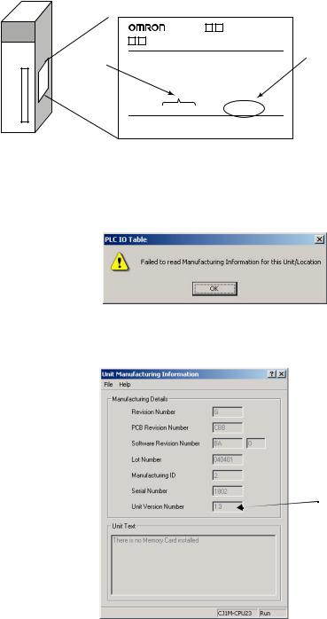
A “unit version” has been introduced to manage Units in the CS/CJ Series according to differences in functionality accompanying Unit upgrades.
The unit version is given to the right of the lot number on the nameplate of the products for which unit versions are being managed, as shown below.
Product nameplate |
|
CS1W- |
|
UNIT |
|
Lot No. |
|
Lot No. 040401 0000 |
Ver.1.3 |
OMRON Corporation |
MADE IN JAPAN |
Unit version
Example for unit version 1.3
Confirming Unit Versions with Support Software
Note
CX-Programmer version 4.0 can be used to confirm the unit version using the
Unit Manufacturing Information.
The (unit versions of) Pre-Ver. 2.0 Units cannot be confirmed Unit Manufacturing Information. The following dialog box is displayed.
In the IO Table Window, right-click and select Unit Manufacturing information - CPU Unit.
The following Unit Manufacturing information Dialog Box will be displayed.
Unit version
Use the above display to confirm the unit version of the Unit connected online.
vi
Using Unit Version Label The following unit version label is provided with the Ethernet Unit.
This label can be attached to the front of the Ethernet Unit to differentiate between Ethernet Units with different unit versions.
Unit Version Notation |
In this manual, the unit version of a Ethernet Unit is given as shown in the fol- |
|||
|
|
lowing table. |
|
|
|
|
|
|
|
Product nameplate |
|
Notation used in this manual |
Special remarks |
|
|
|
|
|
|
Ver. 2.0 or later number |
Ethernet Unit Ver. 1.3 or later |
Information without reference to specific Unit |
|
|
shown to right of the lot |
|
|
Versions applies to all versions of the Unit |
|
number |
|
|
|
|
|
|
|
|
|
Blank to the right of lot |
Pre-Ver. 1.3 Ethernet Units |
|
|
|
number |
|
|
|
|
vii
viii
TABLE OF CONTENTS
PRECAUTIONS . . . . . . . . . . . . . . . . . . . . . . . . . . . . . . . . . . . . . |
xxi |
|
1 |
Intended Audience . . . . . . . . . . . . . . . . . . . . . . . . . . . . . . . . . . . . . . . . . . . . . . . . . . . . . . . . . . . |
xxii |
2 |
General Precautions . . . . . . . . . . . . . . . . . . . . . . . . . . . . . . . . . . . . . . . . . . . . . . . . . . . . . . . . . . |
xxii |
3 |
Safety Precautions. . . . . . . . . . . . . . . . . . . . . . . . . . . . . . . . . . . . . . . . . . . . . . . . . . . . . . . . . . . . |
xxii |
4 |
Operating Environment Precautions . . . . . . . . . . . . . . . . . . . . . . . . . . . . . . . . . . . . . . . . . . . . . . |
xxiii |
5 |
Application Precautions . . . . . . . . . . . . . . . . . . . . . . . . . . . . . . . . . . . . . . . . . . . . . . . . . . . . . . . |
xxiii |
6 Conformance to EC Directives . . . . . . . . . . . . . . . . . . . . . . . . . . . . . . . . . . . . . . . . . . . . . . . . . . |
xxv |
|
SECTION 1 |
1 |
|
Features and System Configuration . . . . . . . . . . . . . . . . . . . . . |
||
1-1 |
Ethernet Unit Function Guide . . . . . . . . . . . . . . . . . . . . . . . . . . . . . . . . . . . . . . . . . . . . . . . . . . . |
2 |
1-2 |
Features . . . . . . . . . . . . . . . . . . . . . . . . . . . . . . . . . . . . . . . . . . . . . . . . . . . . . . . . . . . . . . . . . . . . |
8 |
1-3 |
System Configuration . . . . . . . . . . . . . . . . . . . . . . . . . . . . . . . . . . . . . . . . . . . . . . . . . . . . . . . . . |
11 |
1-4 |
Specifications . . . . . . . . . . . . . . . . . . . . . . . . . . . . . . . . . . . . . . . . . . . . . . . . . . . . . . . . . . . . . . . |
13 |
1-5 |
Overview of Communications Functions . . . . . . . . . . . . . . . . . . . . . . . . . . . . . . . . . . . . . . . . . . |
17 |
1-6 |
Nomenclature and Functions . . . . . . . . . . . . . . . . . . . . . . . . . . . . . . . . . . . . . . . . . . . . . . . . . . . |
23 |
1-7 |
Comparison with Previous Models . . . . . . . . . . . . . . . . . . . . . . . . . . . . . . . . . . . . . . . . . . . . . . . |
27 |
1-8 |
Unit Version Upgrade Information . . . . . . . . . . . . . . . . . . . . . . . . . . . . . . . . . . . . . . . . . . . . . . . |
28 |
SECTION 2 |
29 |
|
Installation and Initial Setup . . . . . . . . . . . . . . . . . . . . . . . . . . . |
||
2-1 |
Overview of Startup Procedure . . . . . . . . . . . . . . . . . . . . . . . . . . . . . . . . . . . . . . . . . . . . . . . . . . |
30 |
2-2 |
Switch Settings . . . . . . . . . . . . . . . . . . . . . . . . . . . . . . . . . . . . . . . . . . . . . . . . . . . . . . . . . . . . . . |
31 |
2-3 |
Mounting to a PLC . . . . . . . . . . . . . . . . . . . . . . . . . . . . . . . . . . . . . . . . . . . . . . . . . . . . . . . . . . . |
33 |
2-4 |
Network Installation . . . . . . . . . . . . . . . . . . . . . . . . . . . . . . . . . . . . . . . . . . . . . . . . . . . . . . . . . . |
34 |
2-5 |
Connecting to the Network . . . . . . . . . . . . . . . . . . . . . . . . . . . . . . . . . . . . . . . . . . . . . . . . . . . . . |
38 |
2-6 |
Creating I/O Tables . . . . . . . . . . . . . . . . . . . . . . . . . . . . . . . . . . . . . . . . . . . . . . . . . . . . . . . . . . . |
39 |
2-7 |
Unit Setup Procedure . . . . . . . . . . . . . . . . . . . . . . . . . . . . . . . . . . . . . . . . . . . . . . . . . . . . . . . . . |
41 |
2-8 |
Using the Web Browser Setting Function . . . . . . . . . . . . . . . . . . . . . . . . . . . . . . . . . . . . . . . . . . |
43 |
2-9 |
Basic Settings . . . . . . . . . . . . . . . . . . . . . . . . . . . . . . . . . . . . . . . . . . . . . . . . . . . . . . . . . . . . . . . |
46 |
2-10 Unit Setup for Particular Applications . . . . . . . . . . . . . . . . . . . . . . . . . . . . . . . . . . . . . . . . . . . . |
50 |
|
2-11 |
Communications Test . . . . . . . . . . . . . . . . . . . . . . . . . . . . . . . . . . . . . . . . . . . . . . . . . . . . . . . . . |
52 |
2-12 |
Converting from Previous Models . . . . . . . . . . . . . . . . . . . . . . . . . . . . . . . . . . . . . . . . . . . . . . . |
53 |
SECTION 3 |
61 |
|
CX-Programmer Unit Setup . . . . . . . . . . . . . . . . . . . . . . . . . . . |
||
3-1 |
Setup . . . . . . . . . . . . . . . . . . . . . . . . . . . . . . . . . . . . . . . . . . . . . . . . . . . . . . . . . . . . . . . . . . . . . . |
62 |
3-2 |
FINS/TCP . . . . . . . . . . . . . . . . . . . . . . . . . . . . . . . . . . . . . . . . . . . . . . . . . . . . . . . . . . . . . . . . . . |
64 |
3-3 |
DNS. . . . . . . . . . . . . . . . . . . . . . . . . . . . . . . . . . . . . . . . . . . . . . . . . . . . . . . . . . . . . . . . . . . . . . . |
66 |
3-4 |
SMTP . . . . . . . . . . . . . . . . . . . . . . . . . . . . . . . . . . . . . . . . . . . . . . . . . . . . . . . . . . . . . . . . . . . . . |
67 |
3-5 |
POP . . . . . . . . . . . . . . . . . . . . . . . . . . . . . . . . . . . . . . . . . . . . . . . . . . . . . . . . . . . . . . . . . . . . . . . |
68 |
3-6 |
Mail Address . . . . . . . . . . . . . . . . . . . . . . . . . . . . . . . . . . . . . . . . . . . . . . . . . . . . . . . . . . . . . . . . |
69 |
3-7 |
Send Mail . . . . . . . . . . . . . . . . . . . . . . . . . . . . . . . . . . . . . . . . . . . . . . . . . . . . . . . . . . . . . . . . . . |
70 |
3-8 |
Receive Mail . . . . . . . . . . . . . . . . . . . . . . . . . . . . . . . . . . . . . . . . . . . . . . . . . . . . . . . . . . . . . . . . |
72 |
3-9 |
Auto Adjust Time . . . . . . . . . . . . . . . . . . . . . . . . . . . . . . . . . . . . . . . . . . . . . . . . . . . . . . . . . . . . |
74 |
3-10 |
HTTP. . . . . . . . . . . . . . . . . . . . . . . . . . . . . . . . . . . . . . . . . . . . . . . . . . . . . . . . . . . . . . . . . . . . . . |
75 |
ix
TABLE OF CONTENTS
SECTION 4 |
|
|
Ethernet Unit Memory Allocations. . . . . . . . . . . . . . . . . . . . . . |
77 |
|
4-1 |
CIO Area Allocations . . . . . . . . . . . . . . . . . . . . . . . . . . . . . . . . . . . . . . . . . . . . . . . . . . . . . . . . . |
78 |
4-2 |
DM Area Allocations . . . . . . . . . . . . . . . . . . . . . . . . . . . . . . . . . . . . . . . . . . . . . . . . . . . . . . . . . |
86 |
4-3 |
Auxiliary Area Data . . . . . . . . . . . . . . . . . . . . . . . . . . . . . . . . . . . . . . . . . . . . . . . . . . . . . . . . . . |
90 |
SECTION 5 |
|
|
Determining IP Addresses . . . . . . . . . . . . . . . . . . . . . . . . . . . . . |
93 |
|
5-1 |
IP Addresses . . . . . . . . . . . . . . . . . . . . . . . . . . . . . . . . . . . . . . . . . . . . . . . . . . . . . . . . . . . . . . . . |
94 |
5-2 IP Addresses in FINS Communications . . . . . . . . . . . . . . . . . . . . . . . . . . . . . . . . . . . . . . . . . . . |
96 |
|
5-3 Private and Global Addresses . . . . . . . . . . . . . . . . . . . . . . . . . . . . . . . . . . . . . . . . . . . . . . . . . . . |
107 |
|
SECTION 6 |
|
|
FINS Communications . . . . . . . . . . . . . . . . . . . . . . . . . . . . . . . . |
113 |
|
6-1 Overview of FINS Communications. . . . . . . . . . . . . . . . . . . . . . . . . . . . . . . . . . . . . . . . . . . . . . |
114 |
|
6-2 |
FINS/UDP Method . . . . . . . . . . . . . . . . . . . . . . . . . . . . . . . . . . . . . . . . . . . . . . . . . . . . . . . . . . . |
116 |
6-3 |
FINS/TCP Method . . . . . . . . . . . . . . . . . . . . . . . . . . . . . . . . . . . . . . . . . . . . . . . . . . . . . . . . . . . |
118 |
6-4 |
Creating Routing Tables . . . . . . . . . . . . . . . . . . . . . . . . . . . . . . . . . . . . . . . . . . . . . . . . . . . . . . . |
122 |
6-5 |
Using FINS Applications . . . . . . . . . . . . . . . . . . . . . . . . . . . . . . . . . . . . . . . . . . . . . . . . . . . . . . |
126 |
6-6 Communicating between OMRON PLCs . . . . . . . . . . . . . . . . . . . . . . . . . . . . . . . . . . . . . . . . . . |
135 |
|
6-7 Precautions on High Traffic in FINS Communications . . . . . . . . . . . . . . . . . . . . . . . . . . . . . . . |
153 |
|
SECTION 7 |
|
|
FINS Commands Addressed to Ethernet Units . . . . . . . . . . . . |
155 |
|
7-1 Command Codes and Response Codes . . . . . . . . . . . . . . . . . . . . . . . . . . . . . . . . . . . . . . . . . . . . |
156 |
|
7-2 |
Socket Applications . . . . . . . . . . . . . . . . . . . . . . . . . . . . . . . . . . . . . . . . . . . . . . . . . . . . . . . . . . |
157 |
7-3 |
Command/Response Reference . . . . . . . . . . . . . . . . . . . . . . . . . . . . . . . . . . . . . . . . . . . . . . . . . |
159 |
SECTION 8 |
|
|
Troubleshooting . . . . . . . . . . . . . . . . . . . . . . . . . . . . . . . . . . . . . |
199 |
|
8-1 |
Troubleshooting with Indicators . . . . . . . . . . . . . . . . . . . . . . . . . . . . . . . . . . . . . . . . . . . . . . . . . |
200 |
8-2 |
Error Status . . . . . . . . . . . . . . . . . . . . . . . . . . . . . . . . . . . . . . . . . . . . . . . . . . . . . . . . . . . . . . . . . |
201 |
8-3 |
Error Log. . . . . . . . . . . . . . . . . . . . . . . . . . . . . . . . . . . . . . . . . . . . . . . . . . . . . . . . . . . . . . . . . . . |
202 |
8-4 |
Troubleshooting Procedures . . . . . . . . . . . . . . . . . . . . . . . . . . . . . . . . . . . . . . . . . . . . . . . . . . . . |
209 |
8-5 Troubleshooting with Response Codes . . . . . . . . . . . . . . . . . . . . . . . . . . . . . . . . . . . . . . . . . . . . |
223 |
|
8-6 Results Storage Area Response Codes . . . . . . . . . . . . . . . . . . . . . . . . . . . . . . . . . . . . . . . . . . . . |
227 |
|
x
|
TABLE OF CONTENTS |
|
Appendices |
|
|
A |
Ethernet Network Parameters . . . . . . . . . . . . . . . . . . . . . . . . . . . . . . . . . . . . . . . . . . . . . . . . . . |
231 |
B |
Buffer Configuration . . . . . . . . . . . . . . . . . . . . . . . . . . . . . . . . . . . . . . . . . . . . . . . . . . . . . . . . . |
233 |
C |
TCP Status Transitions . . . . . . . . . . . . . . . . . . . . . . . . . . . . . . . . . . . . . . . . . . . . . . . . . . . . . . . . |
235 |
D |
ASCII Characters . . . . . . . . . . . . . . . . . . . . . . . . . . . . . . . . . . . . . . . . . . . . . . . . . . . . . . . . . . . . |
237 |
E |
Maintenance . . . . . . . . . . . . . . . . . . . . . . . . . . . . . . . . . . . . . . . . . . . . . . . . . . . . . . . . . . . . . . . . |
239 |
F |
Inspections . . . . . . . . . . . . . . . . . . . . . . . . . . . . . . . . . . . . . . . . . . . . . . . . . . . . . . . . . . . . . . . . . |
241 |
G |
Ethernet Unit Web Function . . . . . . . . . . . . . . . . . . . . . . . . . . . . . . . . . . . . . . . . . . . . . . . . . . . . |
243 |
Index . . . . . . . . . . . . . . . . . . . . . . . . . . . . . . . . . . . . . . . . . . . . . . |
249 |
|
Revision History . . . . . . . . . . . . . . . . . . . . . . . . . . . . . . . . . . . . . |
257 |
|
xi
TABLE OF CONTENTS
xii
About this Manual:
This manual describes the installation and operation of the CS1W-ETN21 and CJ1W-ETN21 Ethernet Units (100Base-TX) and includes the sections described below.
Please read this manual carefully and be sure you understand the information provided before attempting to install or operate the Ethernet Unit. Be sure to read the precautions provided in the following section.
Section 1 introduces the features, describes the system configuration and Unit parts, and provides Unit specifications.
Section 2 explains how to install the Ethernet Unit and make the initial settings required for operation.
Section 3 provides information for setting communications using CX-Programmer.
Section 4 describes the words allocated in the CIO Area and the DM Area for Ethernet Units.
Section 5 explains how to manage and use IP addresses.
Section 6 provides information on communicating on Ethernet Systems and interconnected networks using FINS commands.
Section 7 describes the FINS commands that can be sent to an Ethernet Unit and the responses that are returned by the Ethernet Unit.
Section 8 describes information and procedures that can be used to troubleshoot problems that sometimes occur with Ethernet Unit and Ethernet communications.
Appendices provide information on Ethernet network parameters, the buffer configuration, TCP status transitions, ASCII characters, maintenance, and inspections.
The related Ethernet Units Operation Manual Construction of Applications (W421) provides the following information.
Section |
Contents |
|
|
Section 1 |
Overview of functions for constructing applications. |
|
|
Section 2 |
Information on using mail functions to automatically send I/O memory data from |
|
OMRON PLCs to personal computers. |
|
|
Section 3 |
Information on using mail functions to send commands from OMRON PLCs to per- |
|
sonal computers. |
|
|
Section 4 |
Information on transferring large files between personal computers and OMRON |
|
PLCs. |
|
|
Section 5 |
Information on automatically adjusting the OMRON PLC’s built-in clock. |
|
|
Section 6 |
Information on communicating between general applications (applications not using |
|
FINS) and OMRON PLCs. |
|
|
Section 7 |
Information on using personal computer and UNIX machine socket interfaces to cre- |
|
ate applications using FINS communications. |
|
|
xiii
Relevant Manuals
The following table lists CS and CJ-series manuals that contain information relevant to Ethernet Units.
Manual |
Model |
Name |
Contents |
number |
|
|
|
|
|
|
|
W420 |
CS1W-ETN21 |
Ethernet Units Oper- |
Provides information on operating and installing |
|
CJ1W-ETN21 |
ation Manual |
100Base-TX Ethernet Units, including details on basic |
|
|
Construction of Net- |
settings and FINS communications. |
|
|
works |
Refer to the Communications Commands Reference |
|
|
(this manual) |
|
|
|
Manual (W342) for details on FINS commands that can |
|
|
|
|
be sent to CS-series and CJ-series CPU Units when |
|
|
|
using the FINS communications service. |
|
|
|
|
W421 |
CS1W-ETN21 |
Ethernet Units Oper- |
Provides information on constructing host applications for |
|
CJ1W-ETN21 |
ation Manual |
100Base-TX Ethernet Units, including functions for send- |
|
|
Construction of |
ing/receiving mail, socket service, automatic clock adjust- |
|
|
Applications |
ment, FTP server functions, and FINS communications. |
|
|
|
|
W343 |
CS1W-ETN01 |
Ethernet Units Oper- |
Describes the installation and operation of the 10Base-5 |
|
CS1W-ETN11 |
ation Manual |
and 10Base-T Ethernet Units. |
|
CJ1W-ETN11 |
|
|
|
|
|
|
W342 |
CS1G/H-CPU@@H |
Communications |
Describes the C-series (Host Link) and FINS communica- |
|
CS1G/H-CPU-@@EV1 |
Commands Refer- |
tions commands used when sending communications |
|
CS1D-CPU@@H |
ence Manual |
commands to CS-series and CJ-series CPU Units. |
|
CS1D-CPU@@S |
|
|
|
CJ1M-CPU@@ |
|
|
|
CS1W-SCU21-V1 |
|
|
|
CS1W-SCB21-V1/41-V1 |
|
|
|
CJ1G/H-CPU@@H |
|
|
|
CJ1G-CPU@@P |
|
|
|
CJ1G-CPU@@ |
|
|
|
CJ1W-SCU21-V1/41-V1 |
|
|
|
|
|
|
W339 |
CS1G/H-CPU@@H |
Programmable Con- |
Provides an outline of, and describes the design, installa- |
|
CS1G/H-CPU@@-EV1 |
trollers Operation |
tion, maintenance, and other basic operations for the CS- |
|
|
Manual |
series PLCs. Information is also included on features, |
|
|
|
system configuration, wiring, I/O memory allocations, and |
|
|
|
troubleshooting. |
|
|
|
Use together with the Programmable Controllers Pro- |
|
|
|
gramming Manual (W394). |
|
|
|
|
W393 |
CJ1G/H-CPU@@H |
Programmable Con- |
Provides an outline of, and describes the design, installa- |
|
CJ1G-CPU@@P |
trollers Operation |
tion, maintenance, and other basic operations for the CJ- |
|
CJ1M-CPU@@ |
Manual |
series PLCs. Information is also included on features, |
|
CJ1G-CPU@@ |
|
system configuration, wiring, I/O memory allocations, and |
|
|
|
troubleshooting. |
|
|
|
Use together with the Programmable Controllers Pro- |
|
|
|
gramming Manual (W394). |
|
|
|
|
W394 |
CS1G/H-CPU@@H |
Programmable Con- |
Describes programming, tasks, file memory, and other |
|
CS1G/H-CPU@@EV1 |
trollers Program- |
functions for the CS-series and CJ-series PLCs. |
|
CS1D-CPU@@H |
ming Manual |
Use together with the Programmable Controllers Opera- |
|
CS1D-CPU@@S |
|
tion Manual (W339 for CS-series PLCs and W393 for CJ- |
|
CJ1G/H-CPU@@H |
|
series PLCs). |
|
CJ1G-CPU@@P |
|
|
|
CJ1G-CPU@@ |
|
|
|
CJ1M-CPU@@ |
|
|
W340 |
CS1G/H-CPU@@H |
Programmable Con- |
Describes the ladder diagram programming instructions |
|
CS1G/H-CPU@@EV1 |
trollers Instructions |
supported by CS-series and CJ-series PCs. Use together |
|
CS1D-CPU@@H |
Reference Manual |
with the Programmable Controllers Operation Manual |
|
CS1D-CPU@@S |
|
(W339 for CS-series PLCs and W393 for CJ-series |
|
CJ1G/H-CPU@@H |
|
PLCs), and Programmable Controllers Programming |
|
CJ1G-CPU@@P |
|
Manual (W394). |
|
CJ1G-CPU@@ |
|
|
|
CJ1M-CPU@@ |
|
|
xiv

Manual |
Model |
Name |
Contents |
number |
|
|
|
|
|
|
|
W446 |
WS02-CXPC1-EV6 |
CX-Programmer |
Provides information on how to use the CX-Programmer, |
|
|
Ver. 6.1 Operation |
a Windows-based programming device, and CX-Net, a |
|
|
Manual |
Windows-based network configuration tool. |
|
|
|
Use together with the Programmable Controllers Opera- |
|
|
|
tion Manual (W339 for CS-series PLCs and W393 for CJ- |
|
|
|
series PLCs), Programmable Controllers Programming |
|
|
|
Manual (W394) and the Programmable Controllers |
|
|
|
Instructions Reference Manual (W340) to perform pro- |
|
|
|
gramming. |
|
|
|
|
W444 |
CXONE-AL@@C-E |
CX-One Setup Man- |
Describes operating procedures for the CX-One FA Inte- |
|
|
ual |
grated Tool Package. |
|
|
|
Refer to this manual for operating procedures for the CX- |
|
|
|
One FA Integrated Tool Package. |
|
|
|
|
W445 |
CXONE-AL@@C-E |
CX-Integrator Opera- |
Describes operating procedures for the CX-Integrator net- |
|
|
tion Manual |
work configuration support software for CS/CJ-series |
|
|
|
PLCs. |
|
|
|
Refer to this manual for operating procedures for the CX- |
|
|
|
Integrator network configuration support software for CS/ |
|
|
|
CJ-series PLCs. |
|
|
|
|
W341 |
CQM1H-PRO01-E |
Programming Con- |
Provides information on how to operate the Programming |
|
CQM1-PRO01-E |
soles Operation |
Console. |
|
C200H-PRO27-E |
Manual |
Use together with the Programmable Controllers Opera- |
|
|
|
|
|
|
|
tion Manual (W339 for CS-series PLCs and W393 for CJ- |
|
|
|
series PLCs), Programmable Controllers Programming |
|
|
|
Manual (W394) and the Programmable Controllers |
|
|
|
Instructions Reference Manual (W340) to perform pro- |
|
|
|
gramming. |
|
|
|
|
W336 |
CS1W-SCB21-V1/41-V1 |
Serial Communica- |
Accessing the PLC connected to the CX-Programmer via |
|
CS1W-SCU21-V1 |
tions Boards and |
Ethernet or the host computer or other device connected |
|
CJ1W-SCU21-V1/41-V1 |
Serial Communica- |
to the Serial Communications Board or Unit. |
|
|
tions Units Operation |
Describes the use of Serial Communications Units and |
|
|
Manual |
Boards, including details on hardware, software, and |
|
|
|
|
|
|
|
standard system protocols. |
|
|
|
|
!WARNING Failure to read and understand the information provided in this manual may result in personal injury or death, damage to the product, or product failure. Please read each section in its entirety and be sure you understand the information provided in the section and related sections before attempting any of the procedures or operations given.
xv
xvi

Read and Understand this Manual
Please read and understand this manual before using the product. Please consult your OMRON representative if you have any questions or comments.
Warranty and Limitations of Liability
WARRANTY
OMRON's exclusive warranty is that the products are free from defects in materials and workmanship for a period of one year (or other period if specified) from date of sale by OMRON.
OMRON MAKES NO WARRANTY OR REPRESENTATION, EXPRESS OR IMPLIED, REGARDING NONINFRINGEMENT, MERCHANTABILITY, OR FITNESS FOR PARTICULAR PURPOSE OF THE PRODUCTS. ANY BUYER OR USER ACKNOWLEDGES THAT THE BUYER OR USER ALONE HAS DETERMINED THAT THE PRODUCTS WILL SUITABLY MEET THE REQUIREMENTS OF THEIR INTENDED USE. OMRON DISCLAIMS ALL OTHER WARRANTIES, EXPRESS OR IMPLIED.
LIMITATIONS OF LIABILITY
OMRON SHALL NOT BE RESPONSIBLE FOR SPECIAL, INDIRECT, OR CONSEQUENTIAL DAMAGES, LOSS OF PROFITS OR COMMERCIAL LOSS IN ANY WAY CONNECTED WITH THE PRODUCTS, WHETHER SUCH CLAIM IS BASED ON CONTRACT, WARRANTY, NEGLIGENCE, OR STRICT LIABILITY.
In no event shall the responsibility of OMRON for any act exceed the individual price of the product on which liability is asserted.
IN NO EVENT SHALL OMRON BE RESPONSIBLE FOR WARRANTY, REPAIR, OR OTHER CLAIMS REGARDING THE PRODUCTS UNLESS OMRON'S ANALYSIS CONFIRMS THAT THE PRODUCTS WERE PROPERLY HANDLED, STORED, INSTALLED, AND MAINTAINED AND NOT SUBJECT TO CONTAMINATION, ABUSE, MISUSE, OR INAPPROPRIATE MODIFICATION OR REPAIR.
xvii

Application Considerations
SUITABILITY FOR USE
OMRON shall not be responsible for conformity with any standards, codes, or regulations that apply to the combination of products in the customer's application or use of the products.
At the customer's request, OMRON will provide applicable third party certification documents identifying ratings and limitations of use that apply to the products. This information by itself is not sufficient for a complete determination of the suitability of the products in combination with the end product, machine, system, or other application or use.
The following are some examples of applications for which particular attention must be given. This is not intended to be an exhaustive list of all possible uses of the products, nor is it intended to imply that the uses listed may be suitable for the products:
•Outdoor use, uses involving potential chemical contamination or electrical interference, or conditions or uses not described in this manual.
•Nuclear energy control systems, combustion systems, railroad systems, aviation systems, medical equipment, amusement machines, vehicles, safety equipment, and installations subject to separate industry or government regulations.
•Systems, machines, and equipment that could present a risk to life or property.
Please know and observe all prohibitions of use applicable to the products.
NEVER USE THE PRODUCTS FOR AN APPLICATION INVOLVING SERIOUS RISK TO LIFE OR PROPERTY WITHOUT ENSURING THAT THE SYSTEM AS A WHOLE HAS BEEN DESIGNED TO ADDRESS THE RISKS, AND THAT THE OMRON PRODUCTS ARE PROPERLY RATED AND INSTALLED FOR THE INTENDED USE WITHIN THE OVERALL EQUIPMENT OR SYSTEM.
PROGRAMMABLE PRODUCTS
OMRON shall not be responsible for the user's programming of a programmable product, or any consequence thereof.
xviii

Disclaimers
CHANGE IN SPECIFICATIONS
Product specifications and accessories may be changed at any time based on improvements and other reasons.
It is our practice to change model numbers when published ratings or features are changed, or when significant construction changes are made. However, some specifications of the products may be changed without any notice. When in doubt, special model numbers may be assigned to fix or establish key specifications for your application on your request. Please consult with your OMRON representative at any time to confirm actual specifications of purchased products.
DIMENSIONS AND WEIGHTS
Dimensions and weights are nominal and are not to be used for manufacturing purposes, even when tolerances are shown.
PERFORMANCE DATA
Performance data given in this manual is provided as a guide for the user in determining suitability and does not constitute a warranty. It may represent the result of OMRON's test conditions, and the users must correlate it to actual application requirements. Actual performance is subject to the OMRON Warranty and Limitations of Liability.
ERRORS AND OMISSIONS
The information in this manual has been carefully checked and is believed to be accurate; however, no responsibility is assumed for clerical, typographical, or proofreading errors, or omissions.
xix
xx
PRECAUTIONS
This section provides general precautions for using the CS1W-ETN21 and CJ1W-ETN21 Ethernet Units (100Base-TX).
The information contained in this section is important for the safe and reliable application of Ethernet Units. You must read this section and understand the information contained before attempting to set up or operate an Ethernet Unit.
1 |
Intended Audience . . . . . . . . . . . . . . . . . . . . . . . . . . . . . . . . . . . . . . . . . . . . . |
xxii |
|
2 |
General Precautions . . . . . . . . . . . . . . . . . . . . . . . . . . . . . . . . . . . . . . . . . . . . |
xxii |
|
3 |
Safety Precautions. . . . . . . . . . . . . . . . . . . . . . . . . . . . . . . . . . . . . . . . . . . . . . |
xxii |
|
4 |
Operating Environment Precautions . . . . . . . . . . . . . . . . . . . . . . . . . . . . . . . . |
xxiii |
|
5 |
Application Precautions . . . . . . . . . . . . . . . . . . . . . . . . . . . . . . . . . . . . . . . . . |
xxiii |
|
6 |
Conformance to EC Directives . . . . . . . . . . . . . . . . . . . . . . . . . . . . . . . . . . . . |
xxv |
|
|
6-1 |
Applicable Directives . . . . . . . . . . . . . . . . . . . . . . . . . . . . . . . . . . . . |
xxv |
|
6-2 |
Concepts . . . . . . . . . . . . . . . . . . . . . . . . . . . . . . . . . . . . . . . . . . . . . . |
xxv |
xxi
Intended Audience |
1 |
1 Intended Audience
This manual is intended for the following personnel, who must also have knowledge of electrical systems (an electrical engineer or the equivalent).
•Personnel in charge of installing FA systems.
•Personnel in charge of designing FA systems.
•Personnel in charge of managing FA systems and facilities.
2 General Precautions
The user must operate the product according to the performance specifications described in the operation manuals.
Before using the product under conditions which are not described in the manual or applying the product to nuclear control systems, railroad systems, aviation systems, vehicles, combustion systems, medical equipment, amusement machines, safety equipment, and other systems, machines, and equipment that may have a serious influence on lives and property if used improperly, consult your OMRON representative.
Make sure that the ratings and performance characteristics of the product are sufficient for the systems, machines, and equipment, and be sure to provide the systems, machines, and equipment with double safety mechanisms.
This manual provides information for programming and operating the Unit. Be sure to read this manual before attempting to use the Unit and keep this manual close at hand for reference during operation.
!WARNING It is extremely important that a PLC and all PLC Units be used for the specified purpose and under the specified conditions, especially in applications that can directly or indirectly affect human life. You must consult with your OMRON representative before applying a PLC System to the above-mentioned applications.
3 Safety Precautions
!WARNING Do not attempt to take any Unit apart while the power is being supplied. Doing so may result in electric shock.
!WARNING Do not touch any of the terminals or terminal blocks while the power is being supplied. Doing so may result in electric shock.
!WARNING Do not attempt to disassemble, repair, or modify any Units. Any attempt to do so may result in malfunction, fire, or electric shock.
!Caution Execute online editing only after confirming that no adverse effects will be caused by extending the cycle time. Otherwise, the input signals may not be readable.
xxii

Operating Environment Precautions |
4 |
•Emergency stop circuits, interlock circuits, limit circuits, and similar safety measures must be provided in external control circuits.
!Caution Tighten the screws on the terminal block of the AC Power Supply Unit to the torque specified in the operation manual. The loose screws may result in burning or malfunction.
4 Operating Environment Precautions
!Caution Do not operate the control system in the following locations:
•Locations subject to direct sunlight.
•Locations subject to temperatures or humidity outside the range specified in the specifications.
•Locations subject to condensation as the result of severe changes in temperature.
•Locations subject to corrosive or flammable gases.
•Locations subject to dust (especially iron dust) or salts.
•Locations subject to exposure to water, oil, or chemicals.
•Locations subject to shock or vibration.
!Caution Take appropriate and sufficient countermeasures when installing systems in the following locations:
•Locations subject to static electricity or other forms of noise.
•Locations subject to strong electromagnetic fields.
•Locations subject to possible exposure to radioactivity.
•Locations close to power supplies.
5 Application Precautions
Observe the following precautions when using the Ethernet Unit.
!WARNING Always heed these precautions. Failure to abide by the following precautions could lead to serious or possibly fatal injury.
• Always connect to a ground of 100 Ω or less when installing the Units. Not connecting to a ground of 100 Ω or less may result in electric shock.
xxiii

Application Precautions |
5 |
•Always turn OFF the power supply to the CPU Unit, Slaves, and Communications Units before attempting any of the following. Not turning OFF the power supply may result in malfunction or electric shock.
•Mounting or dismounting I/O Units, CPU Units, Memory Packs, or Master Units.
•Assembling the Units.
•Setting DIP switches or rotary switches.
•Connecting cables or wiring the system.
!Caution Failure to abide by the following precautions could lead to faulty operation of the Ethernet Unit or the system, or could damage the Ethernet Unit. Always heed these precautions.
•Fail-safe measures must be taken by the customer to ensure safety in the event of incorrect, missing, or abnormal signals caused by broken signal lines, momentary power interruptions, or other causes.
•Interlock circuits, limit circuits, and similar safety measures in external circuits (i.e., not in the Programmable Controller) must be provided by the customer.
•Always use the power supply voltages specified in the operation manuals. An incorrect voltage may result in malfunction or burning.
•Take appropriate measures to ensure that the specified power with the rated voltage and frequency is supplied. Be particularly careful in places where the power supply is unstable. An incorrect power supply may result in malfunction.
•Install external breakers and take other safety measures against short-cir- cuiting in external wiring. Insufficient safety measures against short-cir- cuiting may result in burning.
•Do not install the Unit near devices that generate strong high-frequency noise.
•Do not drop the Unit or subject it to excessive vibration or shock.
•Make sure that all the Backplane mounting screws, terminal block screws, and cable connector screws are tightened to the torque specified in the relevant manuals. Incorrect tightening torque may result in malfunction.
•Leave the label attached to the Unit when wiring. Removing the label may result in malfunction if foreign matter enters the Unit.
•Remove the label after the completion of wiring to ensure proper heat dissipation. Leaving the label attached may result in malfunction.
•Use crimp terminals for wiring. Do not connect bare stranded wires directly to terminals. Connection of bare stranded wires may result in burning.
•Double-check all wiring and switch settings before turning ON the power supply. Incorrect wiring may result in burning.
•Wire all connections correctly.
•Mount Units only after checking terminal blocks and connectors completely.
•Make sure that the terminal blocks, expansion cables, and other items with locking devices are locked in place.
•When transporting the Unit, use special packing boxes and protect it from being exposed to excessive vibration or impacts during transportation.
xxiv

Conformance to EC Directives |
6 |
•Check the user program for proper execution before actually running it on the Unit. Not checking the program may result in unexpected operation.
•Observe the following precautions when wiring the communications cable.
•Separate the communications cables from the power lines or high-ten- sion lines.
•Do not bend the communications cables past their natural bending radius.
•Do not pull on the communications cables.
•Do not place heavy objects on top of the communications cables.
•Always lay communications cable inside ducts.
•Use appropriate communications cables.
•Before touching a Unit, be sure to first touch a grounded metallic object in order to discharge any static build-up. Not doing so may result in malfunction or damage.
•Confirm that no adverse effect will occur in the system before attempting any of the following. Not doing so may result in an unexpected operation.
•Changing the operating mode of the PLC (including the setting of the startup operation mode).
•Force-setting/force-resetting any bit in memory.
•Changing the present value of any word or any set value in memory.
6 Conformance to EC Directives
6-1 Applicable Directives
•EMC Directives
•Low Voltage Directive
6-2 Concepts
EMC Directives
OMRON devices that comply with EC Directives also conform to the related EMC standards so that they can be more easily built into other devices or the overall machine. The actual products have been checked for conformity to EMC standards (see the following note). Whether the products conform to the standards in the system used by the customer, however, must be checked by the customer.
EMC-related performance of the OMRON devices that comply with EC Directives will vary depending on the configuration, wiring, and other conditions of the equipment or control panel on which the OMRON devices are installed. The customer must, therefore, perform the final check to confirm that devices and the overall machine conform to EMC standards.
Note Applicable EMS (Electromagnetic Susceptibility) and EMI (Electromagnetic Interference) Standards in the EMC (Electromagnetic Compatibility) standards are as follows:
Unit/Board |
EMS |
EMI |
|
|
|
CS1W-ETN21 |
EN61000-6-2 |
EN61000-6-4 |
|
|
(Radiated emission: 10-m |
CJ1W-ETN21 |
|
|
|
regulations) |
|
|
|
xxv

Conformance to EC Directives |
6 |
Low Voltage Directive
Always ensure that devices operating at voltages of 50 to 1,000 V AC and 75 to 1,500 V DC meet the required safety standards for the PLC (EN61131-2).
xxvi
SECTION 1
Features and System Configuration
This section introduces the features, describes the system configuration and Unit parts, and provides Unit specifications.
1-1 Ethernet Unit Function Guide . . . . . . . . . . . . . . . . . . . . . . . . . . . . . . . . . . . . . |
2 |
||
|
1-1-1 Overall System Configuration Example . . . . . . . . . . . . . . . . . . . . . . |
2 |
|
|
1-1-2 |
Determining the Objectives . . . . . . . . . . . . . . . . . . . . . . . . . . . . . . . |
2 |
1-2 |
Features |
. . . . . . . . . . . . . . . . . . . . . . . . . . . . . . . . . . . . . . . . . . . . . . . . . . . . . . |
8 |
1-3 |
System Configuration . . . . . . . . . . . . . . . . . . . . . . . . . . . . . . . . . . . . . . . . . . . |
11 |
|
|
1-3-1 |
System Configuration . . . . . . . . . . . . . . . . . . . . . . . . . . . . . . . . . . . . |
11 |
|
1-3-2 Devices Required for Constructing a Network. . . . . . . . . . . . . . . . . |
11 |
|
|
1-3-3 Setup Area and Related Peripheral Devices . . . . . . . . . . . . . . . . . . . |
11 |
|
1-4 |
Specifications . . . . . . . . . . . . . . . . . . . . . . . . . . . . . . . . . . . . . . . . . . . . . . . . . |
13 |
|
|
1-4-1 |
General Specifications . . . . . . . . . . . . . . . . . . . . . . . . . . . . . . . . . . . |
13 |
|
1-4-2 |
Dimensions . . . . . . . . . . . . . . . . . . . . . . . . . . . . . . . . . . . . . . . . . . . . |
15 |
|
1-4-3 |
Software Configuration. . . . . . . . . . . . . . . . . . . . . . . . . . . . . . . . . . . |
16 |
1-5 Overview of Communications Functions . . . . . . . . . . . . . . . . . . . . . . . . . . . . |
17 |
||
|
1-5-1 |
FINS Communications Service . . . . . . . . . . . . . . . . . . . . . . . . . . . . |
17 |
|
1-5-2 |
Socket Services . . . . . . . . . . . . . . . . . . . . . . . . . . . . . . . . . . . . . . . . . |
18 |
|
1-5-3 |
FTP Server Function. . . . . . . . . . . . . . . . . . . . . . . . . . . . . . . . . . . . . |
20 |
|
1-5-4 |
Mail Send Function. . . . . . . . . . . . . . . . . . . . . . . . . . . . . . . . . . . . . . |
20 |
|
1-5-5 |
Mail Receive Function . . . . . . . . . . . . . . . . . . . . . . . . . . . . . . . . . . . |
21 |
|
1-5-6 Automatic Clock Adjustment Function . . . . . . . . . . . . . . . . . . . . . . |
22 |
|
|
1-5-7 Specifying Servers by Host Name . . . . . . . . . . . . . . . . . . . . . . . . . . |
22 |
|
1-6 |
Nomenclature and Functions . . . . . . . . . . . . . . . . . . . . . . . . . . . . . . . . . . . . . |
23 |
|
|
1-6-1 |
Component Names . . . . . . . . . . . . . . . . . . . . . . . . . . . . . . . . . . . . . . |
23 |
|
1-6-2 |
Indicators . . . . . . . . . . . . . . . . . . . . . . . . . . . . . . . . . . . . . . . . . . . . . |
25 |
1-7 Comparison with Previous Models . . . . . . . . . . . . . . . . . . . . . . . . . . . . . . . . . |
27 |
||
1-8 Unit Version Upgrade Information . . . . . . . . . . . . . . . . . . . . . . . . . . . . . . . . . |
28 |
||
1

Ethernet Unit Function Guide |
Section 1-1 |
1-1 Ethernet Unit Function Guide
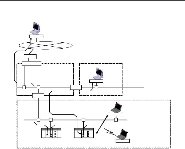
1-1-1 Overall System Configuration Example
The following diagram shows an example of an overall system configuration using Ethernet Units.
(1) Connecting the CX-Programmer to the PLCs online via Ethernet
CX-Programmer
Mail software
FINS |
|
|
|
|
|
|
|
Internet |
|
|
|
|
|
IP router |
|
(5) Transferring large data files between (6) Configuring an independent communications protocol |
||||
|
|
|||||
|
|
personal computers and PLCs |
for the host application using TCP/IP (UDP/IP) |
|||
|
|
Intranet |
|
|
|
|
Firewall |
Server Room |
|
|
Office Floor |
|
|
|
|
|
|
|||
|
DNS server |
FTP software |
|
CX-Programmer |
|
Independent user |
|
POP3 server |
Mail software |
|
SCADA software |
|
application |
|
SMPT server |
|
|
PLC Reporter, Compolet |
|
|
|
SNPT server |
|
|
FinsGateway |
|
|
|
|
|
FTP |
(communications driver) |
UDP/TCP socket |
|
|
|
|
|
|
||
|
Ethernet |
Large files |
|
Ethernet |
|
|
|
|
Router |
|
|
|
|
|
Router |
|
|
|
|
|
|
(4) Receiving mail (data, files) at |
(Factory line) |
|
|
|
CX-Programmer |
|
PLCs |
|
|
|
|
|
|
|
|
|
|
|
|
|
Receiving mail |
|
|
|
NS-series PT |
|
|
|
|
|
|
|
|
|
Writing |
|
|
FINS |
|
FINS |
|
commands |
Ethernet |
|
|
||
|
|
|
|
|
||
|
|
|
|
|
|
|
|
Ethernet Unit |
Ethernet Unit |
(1) Connecting the CX-Programmer to |
|
|
|
|
||
Sending mail |
|
|
PLCs online via Ethernet |
|
|
|
|
||
(3) Capturing PLC changes |
PLC |
PLC |
FINS message |
|
communications |
||||
|
|
|||
and sending the status of |
|
|
Wireless |
|
equipment to an operator |
|
|
||
|
|
|
||
|
FINS message |
Memory Card |
|
|
(7) Automatically adjusting the |
communications |
|
|
|
|
|
|
||
PLC's internal clock |
|
|
FINS |
|
periodically |
(2) Sending and receiving data via Ethernet |
|||
|
|
|||
|
between OMRON PLCs |
|
|
|
1-1-2 Determining the Objectives
Connecting the CX-Programmer to PLCs Online via Ethernet
Connecting within the Same Segment
Use the UDP/IP version of the FINS communications service (i.e., FINS/ UDP). FINS/UDP is supported by many OMRON products and is compatible with earlier Ethernet Units (CS1W-ETN01/ETN11 and CJ1W-ETN11). The CX-Programmer can be connected and used with FINS/UDP even if personal computer middleware (FinsGateway) is not used. FinsGateway (any version) can also be used together with the CX-Programmer.
2

Ethernet Unit Function Guide |
Section 1-1 |
Connecting through Multiple Segments
Using Media with Unreliable Connections, Such as a Wireless LAN
Connecting from a Personal Computer with a Dynamic Private IP Address
Use the TCP/IP version of the FINS communications service (i.e., FINS/TCP). FINS/TCP is a new function supported by these Ethernet Units (CS1WETN21 and CJ1W-ETN21). It provides automatic recovery at the TCP/IP layer from communications errors (such as packet loss) that occur during multilevel routing. For CX-Programmer (version 4.0 or higher), FINS/TCP can be used to directly connect to the PLC online. To use lower versions of the CX-Pro- grammer with FINS/TCP, use FinsGateway (version 2003 or higher) as personal computer middleware.
Use the TCP/IP version of the FINS communications service (i.e., FINS/TCP). FINS/TCP is a new function supported by these Ethernet Units (CS1WETN21 and CJ1W-ETN21). It provides automatic recovery at the TCP/IP layer from communications errors (such as packet loss) resulting from unreliable connections. For CX-Programmer (version 4.0 or higher), FINS/TCP can be used to directly connect to the PLC online. To use lower versions of the CXProgrammer with FINS/TCP, use FinsGateway (version 2003 or higher) as personal computer middleware.
Depending on whether or not the connection will be within the same segment, either use an IP address conversion method for dynamic IP addresses in the UDP/IP version of the FINS communications service or use the TCP/IP version of the FINS communications service.
It is possible to connect online to a PLC using the CX-Programmer from a computer serving as a temporarily connected node or a permanent DHCP client.
For CX-Programmer (version 4.0 or higher), FINS/TCP can be used to directly connect to the PLC online. To use lower versions of the CX-Programmer with FINS/TCP, use FinsGateway (version 2003 or higher) as personal computer middleware.
3
Ethernet Unit Function Guide |
Section 1-1 |
Connecting through multiple segments, such as over the Internet:
Use FINS/TCP.
CX-Programmer
|
FINS |
|
|
|
|
|
Internet |
|
|
|
|
|
IP router |
|
Connecting from a computer with a dynamic private IP address: |
||
|
|
|
|||
|
|
Intranet |
Use FINS/TCP or FINS/UDP. |
|
|
|
Firewall |
|
|
|
|
|
|
|
|
|
|
|
(Server room) |
|
(Office floor) |
|
|
|
|
CX-Programmer |
|
|
|
|
|
|
FINS |
|
|
|
Ethernet |
Router |
|
Ethernet |
|
|
|
|
|
|
|
|
Router |
|
|
|
|
|
|
(Production line) |
|
Connecting within the same segment: |
|
|
|
|
CX-Programmer |
||
|
|
|
Use FINS/UDP. |
||
|
|
|
|
|
|
|
|
|
|
FINS |
|
|
Ethernet |
|
|
|
|
|
Ethernet Unit |
|
Ethernet Unit |
|
|
|
|
|
PLC |
Wireless |
CX-Programmer |
|
|
|
|
||
|
|
|
|
|
|
|
|
|
|
|
Using media with unreliable |
|
|
|
|
|
connections, such as wireless |
|
|
|
|
|
LAN: Use FINS/TCP. |
|
|
|
|
|
FINS |
Reference |
SECTION 6 FINS Communications |
|
|||
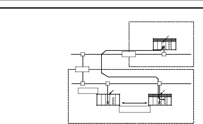
Exchanging Data between OMRON PLCs using Ethernet
Connecting within the Same Segment
Connecting through Multiple Segments
Use the UDP/IP version of the FINS communications service (i.e., FINS/ UDP), and construct applications using the SEND(090), RECV(098), and CMND(490) instructions in the ladder program. FINS/UDP is supported by many OMRON products, and is compatible with earlier Ethernet Units (CS1WETN01/ETN11 and CJ1W-ETN11). The protocol processing for FINS/UDP is simpler than for FINS/TCP, giving FINS/UDP certain advantages in terms of performance. Another feature of FINS/UDP is that it can be used for broadcasting.
On the other hand, with FINS/UDP it is necessary to provide measures, such as retries, for handling communications errors.
Use the TCP/IP version of the FINS communications service (i.e., FINS/TCP), and construct applications using the SEND(090), RECV(098), and CMND(490) instructions in the ladder program. FINS/TCP is the initial function supported by this Ethernet Unit (CS1W-ETN21 and CJ1W-ETN21). It provides automatic recovery at the TCP/IP layer from communications errors (such as packet loss) that occur during multilevel routing.
4
Ethernet Unit Function Guide Section 1-1
Intranet
Production line A
Ethernet Unit
Ethernet
Router
FINS message |
|
Connecting through multiple segments: |
communications |
|
Use FINS/TCP. |
|
|
|
|
Router
Production line B
Ethernet Unit |
|
communications |
|
 PLC
PLC
FINS message communications
Ethernet Unit |
PLC |
Memory Card
|
Connecting within the same segment: |
|
Use FINS/UDP. |
Reference |
SECTION 6 FINS Communications |
Monitoring PLC Changes and Sending Equipment Status to the Operator by E-mail
Operation |
When the mail send function is used, automatic communications applications |
|
via the Internet can be constructed relatively easily. With this Ethernet Unit, |
|
the following mail triggers can be set as PLC changes. When these settings |
|
can be used, no special ladder program is required for sending e-mail. |
|
• When a particular bit (the Mail Send Switch) turns ON |
|
• When values change in particular words (=, <>, <, <=, >=, >) |
|
• When a particular bit changes (either OFF to ON or ON to OFF) |
|
• When a change occurs at the Ethernet Unit (stored in error log) |
|
• When a change occurs at the CPU Unit (e.g., a non-fatal error, a fatal |
|
error, or a mode change) |
|
• At regular intervals |
|
The following data can be sent by e-mail: |
|
• Text (user-created text strings (ASCII data), Ethernet Unit error log data, |
|
and status data) |
|
• Attached files (IOM data created automatically by the Ethernet Unit, data |
|
tables, and files in File Memory) |
|
To use the mail send function, there must be a separate SMTP server on the |
|
network. When using the SMTP server of an Internet Service Provider (ISP), |
|
security measures, such as POP before or SMTP, may be required. (This Unit |
|
handles POP before SMTP.) In addition to the IP address, the host name used |
|
for the DNS service can be specified for the SMTP/POP3 server. |
5
Loading...