


Cat. No. W483-E1-03
SYSMAC CP Series
CP1E-E@@D@-@
CP1E-N@@D@-@
CP1E-NA@@D@-@
CP1E CPU Unit
INSTRUCTIONS REFERENCE MANUAL
OMRON, 2009
All rights reserved. No part of this publication may be reproduced, stored in a retrieval system, or transmitted, in any form, or by any means, mechanical, electronic, photocopying, recording, or otherwise, without the prior written permission of OMRON.
No patent liability is assumed with respect to the use of the information contained herein. Moreover, because OMRON is constantly striving to improve its high-quality products, the information contained in this manual is subject to change without notice. Every precaution has been taken in the preparation of this manual. Nevertheless, OMRON assumes no responsibility for errors or omissions. Neither is any liability assumed for damages resulting from the use of the information contained in this publication.
SYSMAC CP Series CP1E-E@@D@-@ CP1E-N@@D@-@ CP1E-NA@@D@-@
CP1E CPU Unit
Instructions Reference Manual
Revised December 2009

Introduction
Thank you for purchasing a SYSMAC CP-series CP1E Programmable Controller.
This manual contains information required to use the CP1E. Read this manual completely and be sure you understand the contents before attempting to use the CP1E.
Intended Audience
This manual is intended for the following personnel, who must also have knowledge of electrical systems (an electrical engineer or the equivalent).
•Personnel in charge of installing FA systems
•Personnel in charge of designing FA systems
•Personnel in charge of managing FA systems and facilities
Applicable Products
CP-series CP1E CPU Units
•Basic Models CP1E-E D -
A basic model of CPU Unit that support basic control applications using instructions such as basic, movement, arithmetic, and comparison instructions.
•Application Models CP1E-N/NA D -
An application model of CPU Unit that supports connections to Programmable Terminals, inverters, and servo drives.
The CP Series is centered around the CP1H, CP1L, and CP1E CPU Units and is designed with the same basic architecture as the CS and CJ Series.
Always use CP-series Expansion Units and CP-series Expansion I/O Units when expanding I/O capacity. I/O words are allocated in the same way as for the CPM1A/CPM2A PLCs, i.e., using fixed areas for inputs and outputs.
CP1E CPU Unit Instructions Reference Manual(W483) |
1 |

CP1E CPU Unit Manuals
Information on the CP1E CPU Units is provided in the following manuals.
Refer to the appropriate manual for the information that is required.
1
2
3
|
|
This Manual |
CP1E CPU Unit Hardware |
CP1E CPU Unit Software |
CP1E CPU Unit Instructions |
User’s Manual(Cat. No. W479) |
User’s Manual(Cat. No. W480) |
Reference Manual(Cat. No. W483) |
Mounting and |
|
|
Setting Hardware |
|
|
|
|
|
· Names and specifications of the parts of all Units |
|
|
· Basic system configuration for each CPU Unit |
|
|
· Connection methods for Expansion I/O Units |
|
|
and Expansion Units |
|
|
Wiring
·Wiring methods for the power supply
·Wiring methods between external I/O devices and Expansion I/O Units or Expansion Units
Connecting
Online to the PLC
Connecting Cables for CX-Programmer |
Procedures for connecting the |
Support Software |
CX-Programmer Support Software |
4 Software Setup
5
6
7
Software setting methods for the CPU
Units (PLC Setup)
Creating the Program
· Program types and basic information |
Detailed information on |
· CPU Unit operation |
programming instructions |
· Internal memory |
|
· Built-in CPU functions |
|
· Settings |
|
Checking and
Debugging Operation
|
|
· Checking I/O wiring, setting the Auxiliary Area |
|
|
settings, and performing trial operation |
|
|
· Monitoring and debugging with the |
Maintenance and |
|
CX-Programmer |
Troubleshooting |
|
|
|
|
|
|
|
|
Error codes and remedies if a problem occurs
2 |
CP1E CPU Unit Instructions Reference Manual(W483) |

Manual Configuration
The CP1E CPU manuals are organized in the sections listed in the following tables. Refer to the appropriate section in the manuals as required.
CP1E CPU Unit Instructions Reference Manual (Cat. No. W483) (This Manual)
|
Section |
Contents |
Section 1 |
Summary of Instructions |
This section provides a summary of instructions used with a CP1E CPU |
|
|
Unit. |
Section 2 |
Instruction |
This section describes the functions, operands and sample programs of |
|
|
the instructions that are supported by a CP1E CPU Unit. |
Section 3 |
Instruction Execution |
This section provides the execution times for all instructions used with a |
Times and Number of Steps |
CP1E CPU Unit. |
|
Section 4 |
Monitoring and |
This section describes how to monitor and calculate the cycle time of a |
Computing the Cycle Time |
CP1E CPU Unit that can be used in the programs. |
|
Appendices |
The appendices provide a list of instructions by Mnemonic and ASCII |
|
|
|
code table for the CP1E CPU Unit. |
|
|
|
 CP1E CPU Unit Software User’s Manual (Cat. No. W480)
Section |
Contents |
|
|
Section 1 Overview |
This section gives an overview of the CP1E, describes its application |
|
|
|
procedures. |
|
|
|
|
|
|
Section 2 CPU Unit Memory |
This section describes the types of internal memory in a CP1E CPU |
|
|
|
Unit and the data that is stored. |
|
|
|
|
|
|
Section 3 CPU Unit Operation |
This section describes the operation of a CP1E CPU Unit. |
|
|
|
|
|
|
Section 4 Programming Concepts |
This section provides basic information on designing ladder programs |
|
|
|
for a CP1E CPU Unit. |
|
|
|
|
|
|
Section 5 I/O Memory |
This section describes the types of I/O memory areas in a CP1E CPU |
|
|
|
Unit and the details. |
|
|
|
|
|
|
Section 6 I/O Allocation |
This section describes I/O allocation used to exchange data between |
|
|
|
the CP1E CPU Unit and other units. |
|
|
|
|
|
|
Section 7 PLC Setup |
This section describes the PLC Setup, which are used to perform basic |
|
|
|
settings for a CP1E CPU Unit. |
|
|
|
|
|
|
Section 8 Overview and Allocation |
This section lists the built-in functions and describes the overall applica- |
|
|
of Built-in Functions |
tion flow and the allocation of the functions. |
|
|
|
|
|
|
Section 9 Quick-response Inputs |
This section describes the quick-response inputs that can be used to |
|
|
|
read signals that are shorter than the cycle time. |
|
|
|
|
|
|
Section 10 Interrupts |
This section describes the interrupts that can be used with CP1E PLCs, |
|
|
|
including input interrupts and scheduled interrupts. |
|
|
|
|
|
|
Section 11 High-speed Counters |
This section describes the high-speed counter inputs, high-speed |
|
|
|
counter interrupts, and the frequency measurement function. |
|
|
|
|
|
|
Section 12 Pulse Outputs |
This section describes positioning functions such as trapezoidal control, |
|
|
|
jogging, and origin searches. |
|
|
|
|
|
|
Section 13 PWM Outputs |
This section describes the variable-duty-factor pulse (PWM) outputs. |
|
|
|
|
|
|
Section 14 Serial Communications |
This section describes communications with Programmable Terminals |
|
|
|
(PTs) without using communications programming, no-protocol commu- |
|
|
|
nications with general components, and connections with a Modbus- |
|
|
|
RTU Easy Master, Serial PLC Link, and host computer. |
|
|
|
|
|
|
|
|
|
|
CP1E CPU Unit Instructions Reference Manual(W483) |
3 |

|
|
|
|
|
|
|
|
|
|
|
|
Section |
Contents |
|
|
Section 15 |
Analog I/O Function |
This section describes the built-in analog function for NA-type CPU |
|
|
|
|
Units. |
|
|
|
|
|
|
|
Section 16 |
Built-in Functions |
This section describes PID temperature control, clock functions, DM |
|
|
|
|
backup functions, security functions. |
|
|
|
|
|
|
|
Section 17 |
Operating the Program- |
This section describes basic functions of the CX-Programmer, such as |
|
|
ming Device |
using the CX-Programmer to write ladder programs to control the CP1E |
||
|
|
|
CPU Unit, to transfer the programs to the CP1E CPU Unit, and to debug |
|
|
|
|
the programs. |
|
|
|
|
|
|
|
Appendices |
The appendices provide lists of programming instructions, the Auxiliary |
||
|
|
|
Area, cycle time response performance, PLC performance at power |
|
|
|
|
interruptions. |
|
|
|
|
|
|
 CP1E CPU Unit Hardware User’s Manual (Cat. No. W479)
Section |
Contents |
Section 1 Overview and Specifica- |
This section gives an overview of the CP1E, describes its features, and |
tions |
provides its specifications. |
|
|
Section 2 Basic System Configura- |
This section describes the basic system configuration and unit models |
tion and Devices |
of the CP1E. |
|
|
Section 3 Part Names and Functions |
This section describes the part names and functions of the CPU Unit, |
|
Expansion I/O Units, and Expansion Units in a CP1E PLC . |
|
|
Section 4 Programming Device |
This section describes the features of the CX-Programmer used for pro- |
|
gramming and debugging PLCs, as well as how to connect the PLC with |
|
the Programming Device by USB. |
|
|
Section 5 Installation and Wiring |
This section describes how to install and wire CP1E Units. |
|
|
Section 6 Troubleshooting |
This section describes how to troubleshoot problems that may occur |
|
with a CP1E PLC, including the error indications provided by the CP1E |
|
Units. |
|
|
Section 7 Maintenance and Inspec- |
This section describes periodic inspections, the service life of the Bat- |
tion |
tery, and how to replace the Battery. |
|
|
Section 8 Using Expansion Units |
This section describes application methods for Expansion Units. |
and Expansion I/O Units |
|
|
|
Appendices |
The appendices provide information on dimensions, wiring diagrams, |
|
and wiring serial communications for the CP1E. |
|
|
4 |
CP1E CPU Unit Instructions Reference Manual(W483) |
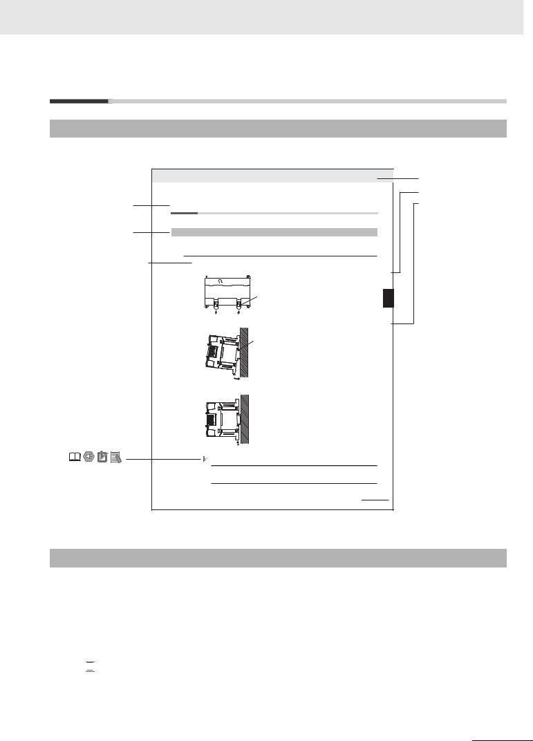
Manual Structure
Page Structure and Icons
The following page structure and icons are used in this manual.
Level 2 heading
Level 3 heading
Step in a procedure
Indicates a step in a procedure.
Special Information (See below.)
Icons are used to indicate precautions and additional information.
5 Installation and wiring
5-2 Installation
5-2-1 Installation Location
 DIN Track Installation
1Use a screwdriver to pull down the DIN Track mounting pins from the back of the Units to release them, and mount the Units to the DIN Track.
DIN Track mounting pins
Release
2Fit the back of the Units onto the DIN Track by catching the top of the Units on the Track and then pressing in at the bottom of the Units, as shown below.
DIN Track
3Press in all of the DIN Track mounting pins to securely lock the Units in place.
DIN Track mounting pins
 Precautions for Correct Use
Tighten terminal block screws and cable screws to the following torques.
M4: 1.2 N·m
M3: 0.5 N·m
Manual name |
|
CP1E CPU Unit Hardware User’s Manual(W479) |
5 - 3 |
Installation 2-5
5
Location Installation 1-2-5
Level 1 heading
Level 2 heading
Level 3 heading
Gives the current headings.

 Page tab
Gives the number of the section.
This illustration is provided only as a sample and may not literally appear in this manual.
Special Information
Special information in this manual is classified as follows:
 Precautions for Safe Use
Precautions on what to do and what not to do to ensure using the product safely.
 Precautions for Correct Use
Precautions on what to do and what not to do to ensure proper operation and performance.


 Additional Information
Additional information to increase understanding or make operation easier.
 References to the location of more detailed or related information.
CP1E CPU Unit Instructions Reference Manual(W483) |
5 |

Terminology and Notation
Term |
Description |
E-type CPU Unit |
A basic model of CPU Unit that support basic control applications using instructions such |
|
as basic, movement, arithmetic, and comparison instructions. |
|
Basic models of CPU Units are called “E-type CPU Units” in this manual. |
|
|
N-type CPU Unit |
An application model of CPU Unit that supports connections to Programmable Terminals, |
|
inverters, and servo drives. |
|
Application models of CPU Units are called “N-type CPU Units” in this manual. |
|
|
NA-type CPU Unit |
An application model of CPU Unit that supports built-in analog and connections to Pro- |
|
grammable Terminals, inverters, and servo drives. |
|
Application models of CPU Units with built-in analog are called “NA-type CPU Units” in |
|
this manual. |
|
|
CX-Programmer |
A programming device that applies for programming and debugging PLCs. |
|
The CX-Programmer includes the Micro PLC Edition CX-Programmer (CX-One Lite), the |
|
CX-Programmer (CX-One) and the CX-Programmer for CP1E. |
|
This manual describes the unique applications and functions of the Micro PLC Edition |
|
CX-Programmer version 9.03 or higher CX-Programmer for CP1E. |
|
“CX-Programmer” refers to the Micro PLC Edition CX-Programmer version 9.03 or higher |
|
CX-Programmer for CP1E in this manual. |
|
Note E20/30/40 and N20/30/40 CPU Units are supported by CX-Programmer version 8.2 |
|
or higher. E10/14, N14/60 and NA20 CPU Units are supported by CX-Programmer |
|
version 9.03 or higher. |
|
|
6 |
CP1E CPU Unit Instructions Reference Manual(W483) |

Sections in this Manual
1
2
1Summary of Instructions
3
2Instructions
|
|
4 |
|
|
Instruction Execution Times and Number |
|
|
3 |
|
||
|
|||
of Steps |
A |
||
|
|||
|
|
|
4Monitoring and Computing the Cycle Time
AAppendices
CP1E CPU Unit Instructions Reference Manual(W483) |
7 |
CONTENTS
Introduction ............................................................................................................... |
1 |
CP1E CPU Unit Manuals ........................................................................................... |
2 |
Manual Structure ....................................................................................................... |
5 |
Safety Precautions .................................................................................................. |
15 |
Precautions for Safe Use........................................................................................ |
18 |
Regulations and Standards.................................................................................... |
19 |
Related Manuals ...................................................................................................... |
20 |
Section 1 |
Summary of Instructions .............................................. |
1-1 |
|
|
|
|
|
1-1 |
Summary of Instructions ........................................................................................................ |
1-2 |
|
Section 2 |
Instructions .................................................................... |
2-1 |
|
|
|
|
|
|
Notation and Layout of Instruction Descriptions ......................................................................... |
2-2 |
|
|
Sequence Input Instructions .......................................................................................................... |
2-5 |
|
|
|
LD/LD NOT ................................................................................................................................................ |
2-7 |
|
|
AND/AND NOT .......................................................................................................................................... |
2-9 |
|
|
OR/OR NOT ............................................................................................................................................. |
2-11 |
|
|
AND LD/OR LD ........................................................................................................................................ |
2-13 |
|
|
NOT .......................................................................................................................................................... |
2-16 |
|
|
UP/DOWN ................................................................................................................................................ |
2-17 |
|
Sequence Output Instructions ..................................................................................................... |
2-18 |
|
|
|
OUT/OUT NOT ........................................................................................................................................ |
2-18 |
|
|
TR ............................................................................................................................................................ |
2-20 |
|
|
KEEP ....................................................................................................................................................... |
2-21 |
|
|
DIFU ......................................................................................................................................................... |
2-25 |
|
|
DIFD ......................................................................................................................................................... |
2-27 |
|
|
SET/RSET ............................................................................................................................................... |
2-29 |
|
|
SETA/RSTA .............................................................................................................................................. |
2-31 |
|
|
SETB/RSTB ............................................................................................................................................. |
2-33 |
|
Sequence Control Instructions..................................................................................................... |
2-35 |
|
|
|
END ......................................................................................................................................................... |
2-38 |
|
|
NOP ......................................................................................................................................................... |
2-39 |
|
|
IL/ILC ....................................................................................................................................................... |
2-40 |
|
|
MILH/MILR/MILC ..................................................................................................................................... |
2-44 |
|
|
JMP/CJP/JME .......................................................................................................................................... |
2-53 |
|
|
FOR/NEXT ............................................................................................................................................... |
2-56 |
|
|
BREAK ..................................................................................................................................................... |
2-59 |
|
Timer and Counter Instructions ................................................................................................... |
2-60 |
|
|
|
TIM/TIMX ................................................................................................................................................. |
2-66 |
|
|
TIMH/TIMHX ............................................................................................................................................ |
2-69 |
|
|
TMHH/TMHHX ......................................................................................................................................... |
2-72 |
|
|
TTIM/TTIMX ............................................................................................................................................. |
2-74 |
|
|
TIML/TIMLX ............................................................................................................................................. |
2-77 |
|
|
CNT/CNTX ............................................................................................................................................... |
2-80 |
8 |
CP1E CPU Unit Instructions Reference Manual(W483) |

|
|
.........................................................................................................................................CNTR/CNTRX |
2-83 |
CNR/CNRX .............................................................................................................................................. |
2-86 |
Comparison Instructions .............................................................................................................. |
2-88 |
=, <>, <, <=, >, >= .................................................................................................................................... |
2-88 |
=DT, <>DT, <DT, <=DT, >DT, >=DT ......................................................................................................... |
2-91 |
CMP/CMPL .............................................................................................................................................. |
2-95 |
CPS/CPSL ............................................................................................................................................... |
2-98 |
TCMP .................................................................................................................................................... |
2-101 |
BCMP .................................................................................................................................................... |
2-103 |
ZCP/ZCPL ............................................................................................................................................. |
2-105 |
Data Movement Instructions....................................................................................................... |
2-108 |
MOV/MOVL/MVN ................................................................................................................................... |
2-108 |
MOVB .................................................................................................................................................... |
2-111 |
MOVD .................................................................................................................................................... |
2-113 |
XFRB ..................................................................................................................................................... |
2-115 |
XFER ..................................................................................................................................................... |
2-117 |
BSET ..................................................................................................................................................... |
2-119 |
XCHG .................................................................................................................................................... |
2-121 |
DIST ...................................................................................................................................................... |
2-123 |
COLL ..................................................................................................................................................... |
2-125 |
Data Shift Instructions ................................................................................................................ |
2-127 |
SFT ........................................................................................................................................................ |
2-127 |
SFTR ..................................................................................................................................................... |
2-129 |
WSFT .................................................................................................................................................... |
2-131 |
ASL ........................................................................................................................................................ |
2-133 |
ASR ....................................................................................................................................................... |
2-134 |
ROL ....................................................................................................................................................... |
2-135 |
ROR ....................................................................................................................................................... |
2-137 |
SLD/SRD ............................................................................................................................................... |
2-139 |
NASL/NSLL ........................................................................................................................................... |
2-141 |
NASR/NSRL .......................................................................................................................................... |
2-144 |
Increment/Decrement Instructions ............................................................................................ |
2-147 |
++/++L ................................................................................................................................................... |
2-147 |
--/--L ...................................................................................................................................................... |
2-150 |
++B/++BL .............................................................................................................................................. |
2-153 |
--B/--BL ................................................................................................................................................. |
2-156 |
Symbol Math Instructions........................................................................................................... |
2-158 |
+/+L ....................................................................................................................................................... |
2-158 |
+C/+CL .................................................................................................................................................. |
2-160 |
+B/+BL ................................................................................................................................................... |
2-162 |
+BC/+BCL ............................................................................................................................................. |
2-164 |
–/–L ........................................................................................................................................................ |
2-166 |
–C/–CL .................................................................................................................................................. |
2-170 |
–B/–BL ................................................................................................................................................... |
2-172 |
–BC/–BCL .............................................................................................................................................. |
2-175 |
*/*L ......................................................................................................................................................... |
2-177 |
*B/*BL .................................................................................................................................................... |
2-179 |
/, /L ......................................................................................................................................................... |
2-181 |
/B, /BL .................................................................................................................................................... |
2-183 |
Conversion Instructions.............................................................................................................. |
2-185 |
BIN/BINL ................................................................................................................................................ |
2-185 |
BCD/BCDL ............................................................................................................................................ |
2-187 |
NEG ....................................................................................................................................................... |
2-189 |
MLPX ..................................................................................................................................................... |
2-191 |
DMPX .................................................................................................................................................... |
2-196 |
ASC ....................................................................................................................................................... |
2-201 |
HEX ....................................................................................................................................................... |
2-205 |
Logic Instructions........................................................................................................................ |
2-210 |
ANDW/ANDL ......................................................................................................................................... |
2-210 |
ORW/ORWL .......................................................................................................................................... |
2-212 |
CP1E CPU Unit Instructions Reference Manual(W483) |
9 |

|
|
.........................................................................................................................................XORW/XORL |
2-214 |
COM/COML ........................................................................................................................................... |
2-216 |
Special Math Instructions ........................................................................................................... |
2-218 |
APR ........................................................................................................................................................ |
2-218 |
BCNT ..................................................................................................................................................... |
2-227 |
Floating-point Math Instructions ................................................................................................ |
2-229 |
FIX/FIXL ................................................................................................................................................. |
2-233 |
FLT/FLTL ................................................................................................................................................ |
2-235 |
+F, –F, *F, /F ........................................................................................................................................... |
2-237 |
=F, <>F, <F, <=F, >F, >=F ........................................................................................................................ |
2-241 |
FSTR ...................................................................................................................................................... |
2-244 |
FVAL ...................................................................................................................................................... |
2-249 |
Table Data Processing Instructions ........................................................................................... |
2-253 |
SWAP ..................................................................................................................................................... |
2-253 |
FCS ........................................................................................................................................................ |
2-255 |
Data Control Instructions............................................................................................................ |
2-257 |
PIDAT ..................................................................................................................................................... |
2-257 |
TPO ........................................................................................................................................................ |
2-269 |
SCL ........................................................................................................................................................ |
2-276 |
SCL2 ...................................................................................................................................................... |
2-280 |
SCL3 ...................................................................................................................................................... |
2-284 |
AVG ........................................................................................................................................................ |
2-287 |
Subroutines Instructions ............................................................................................................ |
2-290 |
SBS ........................................................................................................................................................ |
2-290 |
SBN/RET ............................................................................................................................................... |
2-295 |
Interrupt Control Instructions..................................................................................................... |
2-298 |
MSKS ..................................................................................................................................................... |
2-300 |
CLI ......................................................................................................................................................... |
2-303 |
DI ........................................................................................................................................................... |
2-306 |
EI ............................................................................................................................................................ |
2-307 |
High-speed Counter/Pulse Output Instructions........................................................................ |
2-308 |
INI .......................................................................................................................................................... |
2-308 |
PRV ........................................................................................................................................................ |
2-311 |
CTBL ...................................................................................................................................................... |
2-315 |
SPED ..................................................................................................................................................... |
2-319 |
PULS ...................................................................................................................................................... |
2-323 |
PLS2 ...................................................................................................................................................... |
2-325 |
ACC ....................................................................................................................................................... |
2-331 |
ORG ....................................................................................................................................................... |
2-336 |
PWM ...................................................................................................................................................... |
2-339 |
Step Instructions ......................................................................................................................... |
2-341 |
SNXT/STEP ........................................................................................................................................... |
2-342 |
Basic I/O Unit Instructions .......................................................................................................... |
2-352 |
IORF ...................................................................................................................................................... |
2-352 |
SDEC ..................................................................................................................................................... |
2-354 |
DSW ....................................................................................................................................................... |
2-357 |
MTR ....................................................................................................................................................... |
2-361 |
7SEG ..................................................................................................................................................... |
2-365 |
Serial Communication Instructions ........................................................................................... |
2-369 |
TXD ........................................................................................................................................................ |
2-369 |
RXD ....................................................................................................................................................... |
2-374 |
Clock Instructions........................................................................................................................ |
2-380 |
CADD/CSUB .......................................................................................................................................... |
2-380 |
DATE ...................................................................................................................................................... |
2-385 |
Failure Diagnosis Instructions ................................................................................................... |
2-387 |
FAL ......................................................................................................................................................... |
2-387 |
FALS ...................................................................................................................................................... |
2-393 |
10 |
CP1E CPU Unit Instructions Reference Manual(W483) |

|
|
........................................................................................................................Other Instructions |
2-398 |
STC/CLC ............................................................................................................................................... |
2-398 |
WDT ...................................................................................................................................................... |
2-399 |
Section 3 |
Instruction Execution Times and Number of Steps ... 3-1 |
|||
|
|
|
|
|
3-1 |
CP1E CPU Unit Instruction Execution Times and Number of Steps .................................. |
3-2 |
||
Section 4 |
Monitoring and Computing the Cycle Time................. |
4-1 |
||
|
|
|
|
|
4-1 |
Monitoring the Cycle Time...................................................................................................... |
4-2 |
||
|
|
4-1-1 Monitoring the Cycle Time .......................................................................................................... |
4-2 |
|
4-2 |
Computing the Cycle Time ..................................................................................................... |
4-3 |
||
|
|
4-2-1 CPU Unit Operation Flowchart ................................................................................................... |
4-3 |
|
|
|
4-2-2 |
Cycle Time Overview.................................................................................................................. |
4-4 |
|
|
4-2-3 I/O Refresh Times for PLC Units ................................................................................................ |
4-5 |
|
|
|
4-2-4 Cycle Time Calculation Example ................................................................................................ |
4-6 |
|
|
|
4-2-5 Increase in Cycle Time for Online Editing................................................................................... |
4-6 |
|
Section A |
Appendices .................................................................... |
A-1 |
||
|
|
|
||
|
Alphabetical List of Instructions by Mnemonic ............................................................................. |
A-2 |
||
|
Revision History ....................................................................................... |
Revision-1 |
||
CP1E CPU Unit Instructions Reference Manual(W483) |
11 |

Read and Understand this Manual
Please read and understand this manual before using the product. Please consult your OMRON representative if you have any questions or comments.
Warranty and Limitations of Liability
WARRANTY
OMRON’s exclusive warranty is that the products are free from defects in materials and workmanship for a period of one year (or other period if specified) from date of sale by OMRON.
OMRON MAKES NO WARRANTY OR REPRESENTATION, EXPRESS OR IMPLIED, REGARDING NONINFRINGEMENT, MERCHANTABILITY, OR FITNESS FOR PARTICULAR PURPOSE OF THE PRODUCTS. ANY BUYER OR USER ACKNOWLEDGES THAT THE BUYER OR USER ALONE HAS DETERMINED THAT THE PRODUCTS WILL SUITABLY MEET THE REQUIREMENTS OF THEIR INTENDED USE. OMRON DISCLAIMS ALL OTHER WARRANTIES, EXPRESS OR IMPLIED.
LIMITATIONS OF LIABILITY
OMRON SHALL NOT BE RESPONSIBLE FOR SPECIAL, INDIRECT, OR CONSEQUENTIAL DAMAGES, LOSS OF PROFITS OR COMMERCIAL LOSS IN ANY WAY CONNECTED WITH THE PRODUCTS, WHETHER SUCH CLAIM IS BASED ON CONTRACT, WARRANTY, NEGLIGENCE, OR STRICT LIABILITY.
In no event shall the responsibility of OMRON for any act exceed the individual price of the product on which liability is asserted.
IN NO EVENT SHALL OMRON BE RESPONSIBLE FOR WARRANTY, REPAIR, OR OTHER CLAIMS REGARDING THE PRODUCTS UNLESS OMRON’S ANALYSIS CONFIRMS THAT THE PRODUCTS WERE PROPERLY HANDLED, STORED, INSTALLED, AND MAINTAINED AND NOT SUBJECT TO CONTAMINATION, ABUSE, MISUSE, OR INAPPROPRIATE MODIFICATION OR REPAIR.
12 |
CP1E CPU Unit Instructions Reference Manual(W483) |

Application Considerations
SUITABILITY FOR USE
OMRON shall not be responsible for conformity with any standards, codes, or regulations that apply to the combination of products in the customer’s application or use of the products.
At the customer’s request, OMRON will provide applicable third party certification documents identifying ratings and limitations of use that apply to the products. This information by itself is not sufficient for a complete determination of the suitability of the products in combination with the end product, machine, system, or other application or use.
The following are some examples of applications for which particular attention must be given. This is not intended to be an exhaustive list of all possible uses of the products, nor is it intended to imply that the uses listed may be suitable for the products:
•Outdoor use, uses involving potential chemical contamination or electrical interference, or conditions or uses not described in this manual.
•Nuclear energy control systems, combustion systems, railroad systems, aviation systems, medical equipment, amusement machines, vehicles, safety equipment, and installations subject to separate industry or government regulations.
•Systems, machines, and equipment that could present a risk to life or property.
Please know and observe all prohibitions of use applicable to the products.
NEVER USE THE PRODUCTS FOR AN APPLICATION INVOLVING SERIOUS RISK TO LIFE OR PROPERTY WITHOUT ENSURING THAT THE SYSTEM AS A WHOLE HAS BEEN DESIGNED TO ADDRESS THE RISKS, AND THAT THE OMRON PRODUCTS ARE PROPERLY RATED AND INSTALLED FOR THE INTENDED USE WITHIN THE OVERALL EQUIPMENT OR SYSTEM.
PROGRAMMABLE PRODUCTS
OMRON shall not be responsible for the user’s programming of a programmable product, or any consequence thereof.
CP1E CPU Unit Instructions Reference Manual(W483) |
13 |

Disclaimers
CHANGE IN SPECIFICATIONS
Product specifications and accessories may be changed at any time based on improvements and other reasons.
It is our practice to change model numbers when published ratings or features are changed, or when significant construction changes are made. However, some specifications of the products may be changed without any notice. When in doubt, special model numbers may be assigned to fix or establish key specifications for your application on your request. Please consult with your OMRON representative at any time to confirm actual specifications of purchased products.
DIMENSIONS AND WEIGHTS
Dimensions and weights are nominal and are not to be used for manufacturing purposes, even when tolerances are shown.
PERFORMANCE DATA
Performance data given in this manual is provided as a guide for the user in determining suitability and does not constitute a warranty. It may represent the result of OMRON’s test conditions, and the users must correlate it to actual application requirements. Actual performance is subject to the OMRON Warranty and Limitations of Liability.
ERRORS AND OMISSIONS
The information in this manual has been carefully checked and is believed to be accurate; however, no responsibility is assumed for clerical, typographical, or proofreading errors, or omissions.
14 |
CP1E CPU Unit Instructions Reference Manual(W483) |

Safety Precautions
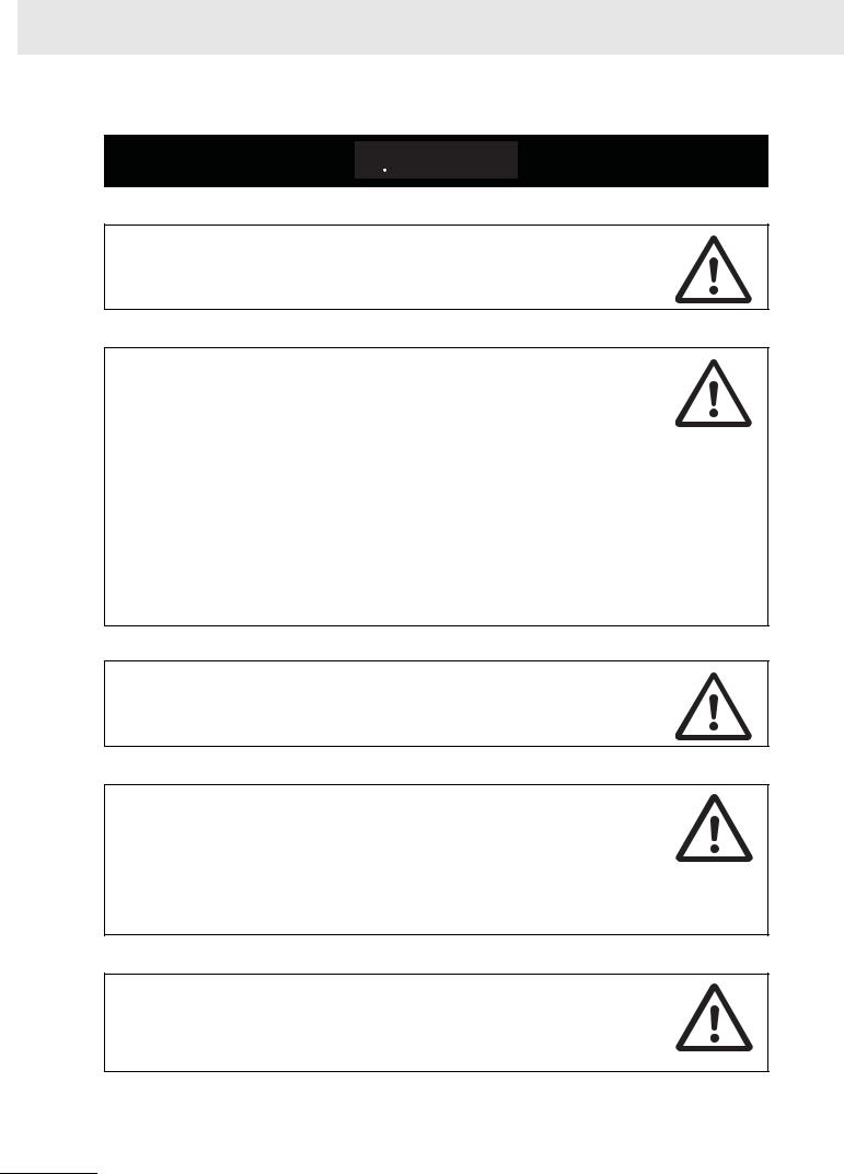
Definition of Precautionary Information
The following notation is used in this manual to provide precautions required to ensure safe usage of a CP-series PLC. The safety precautions that are provided are extremely important to safety. Always read and heed the information provided in all safety precautions.
Indicates an imminently hazardous situation which,
WARNING if not avoided, will result in death or serious injury.
Additionally, there may be severe property damage.
Indicates a potentially hazardous situation which,
Caution if not avoided, may result in minor or moderate injury, or property damage.
 Precautions for Safe Use
Indicates precautions on what to do and what not to do to ensure using the product safely.
 Precautions for Correct Use
Indicates precautions on what to do and what not to do to ensure proper operation and performance.
Symbols
The triangle symbol indicates precautions (including warnings). The specific operation is shown in the triangle and explained in text. This example indicates a precaution for electric shock.
The circle and slash symbol indicates operations that you must not do. The specific operation is shown in the circle and explained in text.
The filled circle symbol indicates operations that you must do. The specific operation is shown in the circle and explained in text. This example shows a general precaution for something that you must do.
The triangle symbol indicates precautions (including warnings). The specific operation is shown in the triangle and explained in text. This example indicates a general precaution.
The triangle symbol indicates precautions (including warnings). The specific operation is shown in the triangle and explained in text. This example indicates a precaution for hot surfaces.
CP1E CPU Unit Instructions Reference Manual(W483) |
15 |
 Caution
Be sure to sufficiently confirm the safety at the destination when you transfer the program or I/O memory or perform procedures to change the I/O memory.
Devices connected to PLC outputs may incorrectly operate regardless of the operating mode of the CPU Unit.
With an E-type CPU Unit or with an N/NA-type CPU Unit without a Battery, the contents of the DM Area (D) *, Holding Area (H), the Counter Present Values (C), the status of Counter Completion Flags (C), and the status of bits in the Auxiliary Area (A) related to clock functions may be unstable when the power supply is turned ON.
*This does not apply to areas backed up to EEPROM using the DM backup function.
If the DM backup function is being used, be sure to use one of the following methods for initialization.
1.Clearing All Areas to All Zeros
Select the Clear Held Memory (HR/DM/CNT) to Zero Check Box in the Startup Data Read Area in the PLC Setup.
2.Clearing Specific Areas to All Zeros or Initializing to Specific Values Make the settings from a ladder program.
If the data is not initialized, the unit or device may operate unexpectedly because of unstable data.
Execute online edit only after confirming that no adverse effects will be caused by extending the cycle time.
Otherwise, the input signals may not be readable.
The DM Area (D), Holding Area (H), Counter Completion Flags (C), and Counter Present Values (C) will be held by the Battery if a Battery is mounted in a CP1E- N/NA D - CPU Unit. When the battery voltage is low, however, I/O memory areas that are held (including the DM, Holding, and Counter Areas) will be unstable. The unit or device may operate unexpectedly because of unstable data.
Use the Battery Error Flag or other measures to stop outputs if external outputs are performed from a ladder program based on the contents of the DM Area or other I/O memory areas.
Sufficiently check safety if I/O bit status or present values are monitored in the Ladder Section Pane or present values are monitored in the Watch Pane.
If bits are set, reset, force-set, or force-reset by inadvertently pressing a shortcut key, devices connected to PLC outputs may operate incorrectly regardless of the operating mode.
16 |
CP1E CPU Unit Instructions Reference Manual(W483) |

 Caution
Program so that the memory area of the start address is not exceeded when using a word address or symbol for the offset.
For example, write the program so that processing is executed only when the indirect specification does not cause the final address to exceed the memory area by using an input comparison instruction or other instruction.
If an indirect specification causes the address to exceed the area of the start address, the system will access data in other area, and unexpected operation may occur.
Set the temperature range according to the type of temperature sensor connected to the Unit.
Temperature data will not be converted correctly if the temperature range does not match the sensor.
Do not set the temperature range to any values other than those for which temperature ranges are given in the following table.
An incorrect setting may cause operating errors.
CP1E CPU Unit Instructions Reference Manual(W483) |
17 |
Precautions for Safe Use
Observe the following precautions when using a CP-series PLC.
Handling
•To initialize the DM Area, back up the initial contents for the DM Area to backup memory using one of the following methods.
•Set the number of words of the DM Area to be backed up starting with D0 in the Number of CH of DM for backup Box in the Startup Data Read Area.
•Include programming to back up specified words in the DM Area to built-in EEPROM by turning ON A751.15 (DM Backup Save Start Bit).
•Check the ladder program for proper execution before actually running it on the Unit. Not checking the program may result in an unexpected operation.
•The ladder program and parameter area data in the CP1E CPU Units are backed up in the built-in EEPROM backup memory. The BKUP indicator will light on the front of the CPU Unit when the backup operation is in progress. Do not turn OFF the power supply to the CPU Unit when the BKUP indicator is lit. The data will not be backed up if power is turned OFF and a memory error will occur the next time the power supply is turned ON.
•With a CP1E CPU Unit, data memory can be backed up to the built-in EEPROM backup memory. The BKUP indicator will light on the front of the CPU Unit when backup is in progress. Do not turn OFF the power supply to the CPU Unit when the BKUP indicator is lit. If the power is turned OFF during a backup, the data will not be backed up and will not be transferred to the DM Area in RAM the next time the power supply is turned ON.
•Before replacing the battery, supply power to the CPU Unit for at least 30 minutes and then complete battery replacement within 5 minutes. Memory data may be corrupted if this precaution is not observed.
•The equipment may operate unexpectedly if inappropriate parameters are set. Even if the appropriate parameters are set, confirm that equipment will not be adversely affected before transferring the parameters to the CPU Unit.
•Before starting operation, confirm that the contents of the DM Area is correct.
•After replacing the CPU Unit, make sure that the required data for the DM Area, Holding Area, and other memory areas has been transferred to the new CPU Unit before restarting operation.
•Do not attempt to disassemble, repair, or modify any Units. Any attempt to do so may result in malfunction, fire, or electric shock.
•Confirm that no adverse effect will occur in the system before attempting any of the following. Not doing so may result in an unexpected operation.
•Changing the operating mode of the PLC (including the setting of the startup operating mode).
•Force-setting/force-resetting any bit in memory.
•Changing the present value of any word or any set value in memory.
External Circuits
•Always configure the external circuits to turn ON power to the PLC before turning ON power to the control system. If the PLC power supply is turned ON after the control power supply, temporary errors may result in control system signals because the output terminals on DC Output Units and other Units will momentarily turn ON when power is turned ON to the PLC.
•Fail-safe measures must be taken by the customer to ensure safety in the event that outputs from output terminals remain ON as a result of internal circuit failures, which can occur in relays, transistors, and other elements.
•If the I/O Hold Bit is turned ON, the outputs from the PLC will not be turned OFF and will maintain their previous status when the PLC is switched from RUN or MONITOR mode to PROGRAM mode. Make sure that the external loads will not produce dangerous conditions when this occurs. (When operation stops for a fatal error, including those produced with the FALS instruction, all outputs from PLC will be turned OFF and only the internal output status in the CPU Unit will be maintained.)
18 |
CP1E CPU Unit Instructions Reference Manual(W483) |

Regulations and Standards
Trademarks
SYSMAC is a registered trademark for Programmable Controllers made by OMRON Corporation. CX-One is a registered trademark for Programming Software made by OMRON Corporation. Windows is a registered trademark of Microsoft Corporation.
Other system names and product names in this document are the trademarks or registered trademarks of their respective companies.
CP1E CPU Unit Instructions Reference Manual(W483) |
19 |

Related Manuals
The following manuals are related to the CP1E. Use them together with this manual.
Manual name |
Cat. No. |
Model numbers |
Application |
|
|
Contents |
SYSMAC CP Series |
W483 |
CP1E-E D - |
To learn program- |
Describes each programming instruction in |
||
CP1E CPU Unit Instruc- |
|
CP1E-N D - |
ming instructions in |
detail. |
||
tions Reference Manual |
|
detail |
|
|
|
|
|
CP1E-NA D - |
When programming, use this manual together |
||||
(this manual) |
|
|
||||
|
|
with the CP1E CPU Unit Software User’s Man- |
||||
|
|
|
||||
|
|
|
|
|||
|
|
|
|
ual (Cat. No. W480). |
||
SYSMAC CP Series |
W480 |
CP1E-E D - |
To learn the software |
Describes the following information for CP1E |
||
CP1E CPU Unit Soft- |
|
CP1E-N D - |
specifications of the |
PLCs. |
||
ware User’s Manual |
|
CP1E PLCs |
|
|
|
|
|
CP1E-NA D - |
• |
CPU Unit operation |
|||
|
|
|
||||
|
|
|
• |
|
|
|
|
|
|
|
Internal memory |
||
|
|
|
|
• |
Programming |
|
|
|
|
|
• |
Settings |
|
|
|
|
|
• CPU Unit built-in functions |
||
|
|
|
|
|
• |
Interrupts |
|
|
|
|
|
• High-speed counter inputs |
|
|
|
|
|
|
• |
Pulse outputs |
|
|
|
|
|
• |
Serial communications |
|
|
|
|
|
• |
Other functions |
|
|
|
|
|
||
|
|
|
Use this manual together with the CP1E CPU Unit Hardware User’s |
|||
|
|
|
Manual (Cat. No. W479) and Instructions Reference Manual (Cat. No. |
|||
|
|
|
W483). |
|
|
|
|
|
|
|
|
||
SYSMAC CP Series |
W479 |
CP1E-E D - |
To learn the hard- |
Describes the following information for CP1E |
||
CP1E CPU Unit Hard- |
|
CP1E-N D - |
ware specifications |
PLCs. |
||
ware User’s Manual |
|
of the CP1E PLCs |
|
|
|
|
|
CP1E-NA D - |
• |
Overview and features |
|||
|
|
|
||||
|
|
|
• |
|
|
|
|
|
|
|
Basic system configuration |
||
|
|
|
|
• |
Part names and functions |
|
|
|
|
|
• |
Installation and settings |
|
|
|
|
|
• |
Troubleshooting |
|
|
|
|
|
|
||
|
|
|
Use this manual together with the CP1E CPU Unit Software User’s |
|||
|
|
|
Manual (Cat. No. W480) and Instructions Reference Manual (Cat. No. |
|||
|
|
|
W483). |
|
|
|
|
|
|
|
|
||
CS/CJ/CP/NSJ Series |
W342 |
CS1G/H-CPU H |
To learn communica- |
Describes |
||
Communications Com- |
|
CS1G/H-CPU -V1 |
tions commands for |
1) C-mode commands and |
||
mands Reference Man- |
|
CS/CJ/CP/NSJ- |
||||
|
CS1D-CPU H |
2) FINS commands in detail. |
||||
ual |
|
series Controllers in |
||||
|
|
|
|
|||
|
|
Read this manual for details on C-mode and |
||||
|
|
CS1D-CPU S |
detail |
|||
|
|
FINS commands addressed to CPU Units. |
||||
|
|
CS1W-SCU -V1 |
|
|||
|
|
|
|
|
|
|
|
|
CS1W-SCB -V1 |
Note This manual describes commands addressed to CPU Units. It |
|||
|
|
CJ1G/H-CPU H |
does not cover commands addressed to other Units or ports (e.g., |
|||
|
|
serial communications ports on CPU Units, communications ports |
||||
|
|
|
||||
|
|
|
on Serial Communications Units/Boards, and other Communica- |
|||
|
|
CJ1G-CPU P |
tions Units). |
|
|
|
|
|
CJ1M-CPU |
|
|
|
|
|
|
|
|
|
|
|
|
|
CJ1G-CPU |
|
|
|
|
|
|
CJ1W-SCU -V1 |
|
|
|
|
|
|
|
|
|
||
SYSMAC CP Series |
W461 |
CP1L-L10D - |
To learn the basic |
Describes the following information for |
||
CP1L/CP1E CPU Unit |
|
CP1L-L14D - |
setup methods of the |
CP1L/CP1E PLCs. |
||
|
CP1L/CP1E PLCs |
|
|
|
||
|
|
CP1L-L20D - |
• Basic configuration and component names |
|||
Introduction Manual |
|
|
||||
|
|
|
• |
|
|
|
|
|
CP1L-M30D - |
|
Mounting and wiring |
||
|
|
|
• Programming, data transfer, and debugging |
|||
|
|
CP1L-M40D - |
|
|||
|
|
|
|
using the CX-Programmer |
||
|
|
|
|
|
||
|
|
CP1L-M60D - |
|
• |
Application program examples |
|
|
|
|
|
|||
|
|
CP1E-E D - |
|
|
|
|
|
|
CP1E-N D - |
|
|
|
|
|
|
CP1E-NA D - |
|
|
|
|
|
|
|
|
|
|
|
20 |
CP1E CPU Unit Instructions Reference Manual(W483) |

1
Summary of Instructions
This section provides a summary of instructions used with a CP1E CPU Unit.
1-1 Summary of Instructions . . . . . . . . . . . . . . . . . . . . . . . . . . . . . . . . . . . . . . . . |
1-2 |
CP1E CPU Unit Instructions Reference Manual(W483) |
1-1 |

1 Summary of Instructions
1-1 Summary of Instructions
There are 200 types of instructions can be used by CP1E.
The following table lists the instructions by function. Refer to the reference pages for the detail of each instruction.
Instrucion |
Instruction |
Mnemonic |
FUN |
Function |
Page |
|
Type |
No. |
|||||
|
|
|
|
|||
Sequence |
LOAD |
LD |
- |
Indicates a logical start and creates an ON/OFF execution condition based on |
2-7 |
|
Input Instruc- |
|
|
|
the ON/OFF status of the specified operand bit. |
|
|
|
@LD |
- |
|
|||
tions |
|
|
|
|||
|
|
|
|
|
||
|
%LD |
- |
|
|
||
|
|
|
|
|||
|
|
|
|
|
|
|
|
|
!LD |
- |
|
|
|
|
|
|
|
|
|
|
|
|
!@LD |
- |
|
|
|
|
|
|
|
|
|
|
|
|
!%LD |
- |
|
|
|
|
|
|
|
|
|
|
|
LOAD NOT |
LD NOT |
- |
Indicates a logical start and creates an ON/OFF execution condition based on |
2-7 |
|
|
|
|
|
the reverse of the ON/OFF status of the specified operand bit. |
|
|
|
|
@LD NOT |
- |
|
||
|
|
|
|
|||
|
|
|
|
|
|
|
|
|
%LD NOT |
- |
|
|
|
|
|
|
|
|
|
|
|
|
!LD NOT |
- |
|
|
|
|
|
|
|
|
|
|
|
|
!@LD NOT |
- |
|
|
|
|
|
|
|
|
|
|
|
|
!%LD NOT |
- |
|
|
|
|
|
|
|
|
|
|
|
AND |
AND |
- |
Takes a logical AND of the status of the specified operand bit and the current |
2-9 |
|
|
|
|
|
execution condition. |
|
|
|
|
@AND |
- |
|
||
|
|
|
|
|||
|
|
|
|
|
|
|
|
|
%AND |
- |
|
|
|
|
|
|
|
|
|
|
|
|
!AND |
- |
|
|
|
|
|
|
|
|
|
|
|
|
!@AND |
- |
|
|
|
|
|
|
|
|
|
|
|
|
!%AND |
- |
|
|
|
|
|
|
|
|
|
|
|
AND NOT |
AND NOT |
- |
Reverses the status of the specified operand bit and takes a logical AND with |
2-9 |
|
|
|
|
|
the current execution condition. |
|
|
|
|
@AND NOT |
- |
|
||
|
|
|
|
|||
|
|
|
|
|
|
|
|
|
%AND NOT |
- |
|
|
|
|
|
|
|
|
|
|
|
|
!AND NOT |
- |
|
|
|
|
|
|
|
|
|
|
|
|
!@AND NOT |
- |
|
|
|
|
|
|
|
|
|
|
|
|
!%AND NOT |
- |
|
|
|
|
|
|
|
|
|
|
|
OR |
OR |
- |
Takes a logical OR of the ON/OFF status of the specified operand bit and the |
2-11 |
|
|
|
|
|
current execution condition. |
|
|
|
|
@OR |
- |
|
||
|
|
|
|
|||
|
|
|
|
|
|
|
|
|
%OR |
- |
|
|
|
|
|
|
|
|
|
|
|
|
!OR |
- |
|
|
|
|
|
|
|
|
|
|
|
|
!@OR |
- |
|
|
|
|
|
|
|
|
|
|
|
|
!%OR |
- |
|
|
|
|
|
|
|
|
|
|
|
OR NOT |
OR NOT |
- |
Reverses the status of the specified bit and takes a logical OR with the current |
2-11 |
|
|
|
|
|
execution condition. |
|
|
|
|
@OR NOT |
- |
|
||
|
|
|
|
|||
|
|
|
|
|
|
|
|
|
%OR NOT |
- |
|
|
|
|
|
|
|
|
|
|
|
|
!OR NOT |
- |
|
|
|
|
|
|
|
|
|
|
|
|
!@OR NOT |
- |
|
|
|
|
|
|
|
|
|
|
|
|
!%OR NOT |
- |
|
|
|
|
|
|
|
|
|
|
|
AND LOAD |
AND LD |
- |
Takes a logical AND between logic blocks. |
2-13 |
|
|
|
|
|
|
|
|
|
OR LOAD |
OR LD |
- |
Takes a logical OR between logic blocks. |
2-13 |
|
|
|
|
|
|
|
|
|
NOT |
NOT |
520 |
Reverses the execution condition. |
2-16 |
|
|
|
|
|
|
|
|
|
CONDITION ON |
UP |
521 |
UP(521) turns ON the execution condition for one cycle when the execution |
2-17 |
|
|
|
|
|
condition goes from OFF to ON. |
|
|
|
|
|
|
|
|
|
|
CONDITION OFF |
DOWN |
522 |
DOWN(522) turns ON the execution condition for one cycle when the execution |
2-17 |
|
|
|
|
|
condition goes from ON to OFF. |
|
|
|
|
|
|
|
|
1-2 |
CP1E CPU Unit Instructions Reference Manual(W483) |

1 Summary of Instructions
Instrucion |
Instruction |
Mnemonic |
FUN |
Function |
Page |
|
Type |
No. |
|||||
|
|
|
|
|||
Sequence |
OUTPUT |
OUT |
- |
Outputs the result (execution condition) of the logical processing to the speci- |
2-18 |
|
Output |
|
|
|
fied bit. |
|
|
|
!OUT |
- |
|
|||
Instructions |
|
|
|
|||
|
|
|
|
|
||
OUTPUT NOT |
OUT NOT |
- |
Reverses the result (execution condition) of the logical processing, and outputs |
2-18 |
||
|
||||||
|
|
|
|
it to the specified bit. |
|
|
|
|
!OUT NOT |
- |
|
||
|
|
|
|
|||
|
|
|
|
|
|
|
|
TR Bits |
TR |
- |
TR bits are used to temporarily retain the ON/OFF status of execution condi- |
2-20 |
|
|
|
|
|
tions in a program when programming in mnemonic code. |
|
|
|
|
|
|
|
|
|
|
KEEP |
KEEP |
011 |
Operates as a latching relay. |
2-21 |
|
|
|
|
|
|
|
|
|
|
!KEEP |
|
|
|
|
|
|
|
|
|
|
|
|
DIFFERENTIATE |
DIFU |
013 |
DIFU(013) turns the designated bit ON for one cycle when the execution condi- |
2-25 |
|
|
UP |
|
|
tion goes from OFF to ON (rising edge). |
|
|
|
!DIFU |
|
|
|||
|
|
|
|
|
||
|
|
|
|
|
|
|
|
DIFFERENTIATE |
DIFD |
014 |
DIFD(014) turns the designated bit ON for one cycle when the execution condi- |
2-27 |
|
|
DOWN |
|
|
tion goes from ON to OFF (falling edge). |
|
|
|
!DIFD |
|
|
|||
|
|
|
|
|
||
|
|
|
|
|
|
|
|
SET |
SET |
- |
SET turns the operand bit ON when the execution condition is ON. |
2-29 |
|
|
|
|
|
|
|
|
|
|
@SET |
- |
|
|
|
|
|
|
|
|
|
|
|
|
%SET |
- |
|
|
|
|
|
|
|
|
|
|
|
|
!SET |
- |
|
|
|
|
|
|
|
|
|
|
|
|
!@SET |
- |
|
|
|
|
|
|
|
|
|
|
|
|
!%SET |
- |
|
|
|
|
|
|
|
|
|
|
|
RESET |
RSET |
- |
RSET turns the operand bit OFF when the execution condition is ON. |
2-29 |
|
|
|
|
|
|
|
|
|
|
@RSET |
- |
|
|
|
|
|
|
|
|
|
|
|
|
%RSET |
- |
|
|
|
|
|
|
|
|
|
|
|
|
!RSET |
- |
|
|
|
|
|
|
|
|
|
|
|
|
!@RSET |
- |
|
|
|
|
|
|
|
|
|
|
|
|
!%RSET |
- |
|
|
|
|
|
|
|
|
|
|
|
MULTIPLE BIT SET |
SETA |
530 |
SETA(530) turns ON the specified number of consecutive bits. |
2-31 |
|
|
|
|
|
|
|
|
|
|
@SETA |
|
|
|
|
|
|
|
|
|
|
|
|
MULTIPLE BIT |
RSTA |
531 |
RSTA(531) turns OFF the specified number of consecutive bits. |
2-31 |
|
|
RESET |
|
|
|
|
|
|
@RSTA |
|
|
|
||
|
|
|
|
|
||
|
|
|
|
|
|
|
|
SINGLE BIT SET |
SETB |
532 |
SETB(532) turns ON the specified bit in the specified word when the execution |
2-33 |
|
|
|
|
|
condition is ON. |
|
|
|
|
@SETB |
|
|
||
|
|
|
|
|
||
|
|
|
|
Unlike the SET instruction, SETB(532) can be used to set a bit in a DM word. |
|
|
|
|
!SETB |
|
|
||
|
|
|
|
|
||
|
|
|
|
|
|
|
|
|
!@SETB |
|
|
|
|
|
|
|
|
|
|
|
|
SINGLE BIT RESET |
RSTB |
533 |
RSTB(533) turns OFF the specified bit in the specified word when the execu- |
2-33 |
|
|
|
|
|
tion condition is ON. |
|
|
|
|
@RSTB |
|
|
||
|
|
|
|
|
||
|
|
|
|
Unlike the RSET instruction, RSTB(533) can be used to reset a bit in a DM |
|
|
|
|
!RSTB |
|
|
||
|
|
|
word. |
|
||
|
|
|
|
|
||
|
|
!@RSTB |
|
|
|
|
|
|
|
|
|
|
Instructions of Summary 1-1
1
CP1E CPU Unit Instructions Reference Manual(W483) |
1-3 |

1 Summary of Instructions
Instrucion |
Instruction |
Mnemonic |
FUN |
Function |
Page |
|
Type |
No. |
|||||
|
|
|
|
|||
Sequence |
END |
END |
001 |
Indicates the end of a program. |
2-38 |
|
Control |
|
|
|
|
|
|
NO OPERATION |
NOP |
000 |
This instruction has no function. (No processing is performed for NOP(000).) |
2-39 |
||
Instructions |
||||||
|
|
|
|
|
||
INTERLOCK |
IL |
002 |
Interlocks all outputs between IL(002) and ILC(003) when the execution condi- |
2-40 |
||
|
||||||
|
|
|
|
tion for IL(002) is OFF. |
|
|
|
|
|
|
|
|
|
|
INTERLOCK |
ILC |
003 |
All outputs between IL(002) and ILC(003) are interlocked when the execution |
2-40 |
|
|
CLEAR |
|
|
condition for IL(002) is OFF. |
|
|
|
|
|
|
|
|
|
|
MULTI-INTERLOCK |
MILH |
517 |
When the execution condition for MILH(517) is OFF, the outputs for all instruc- |
2-44 |
|
|
DIFFERENTIATION |
|
|
tions between that MILH(517) instruction and the next MILC(519) instruction |
|
|
|
HOLD |
|
|
are interlocked. |
|
|
|
|
|
|
|
|
|
|
MULTI-INTERLOCK |
MILR |
518 |
When the execution condition for MILR(518) is OFF, the outputs for all instruc- |
2-44 |
|
|
DIFFERENTIATION |
|
|
tions between that MILR(518) instruction and the next MILC(519) instruction |
|
|
|
RELEASE |
|
|
are interlocked. |
|
|
|
|
|
|
|
|
|
|
MULTI-INTERLOCK |
MILC |
519 |
Clears an interlock started by an MILH(517) or MILR(518) with the same inter- |
2-44 |
|
|
CLEAR |
|
|
lock number. |
|
|
|
|
|
|
|
|
|
|
JUMP |
JMP |
004 |
When the execution condition for JMP(004) is OFF, program execution jumps |
2-53 |
|
|
|
|
|
directly to the first JME(005) in the program with the same jump number. |
|
|
|
|
|
|
|
|
|
|
JUMP END |
JME |
005 |
Indicates the end of a jump initiated by JMP(004) or CJP(510). |
2-53 |
|
|
|
|
|
|
|
|
|
CONDITIONAL |
CJP |
510 |
The operation of CJP(510) is the basically the opposite of JMP(004). When the |
2-53 |
|
|
JUMP |
|
|
execution condition for CJP(510) is ON, program execution jumps directly to the |
|
|
|
|
|
|
first JME(005) in the program with the same jump number. |
|
|
|
|
|
|
|
|
|
|
FOR LOOP |
FOR |
512 |
The instructions between FOR(512) and NEXT(513) are repeated a specified |
2-56 |
|
|
|
|
|
number of times. |
|
|
|
|
|
|
|
|
|
|
NEXT LOOP |
NEXT |
513 |
The instructions between FOR(512) and NEXT(513) are repeated a specified |
2-56 |
|
|
|
|
|
number of times. |
|
|
|
|
|
|
|
|
|
|
BREAK LOOP |
BREAK |
514 |
Programmed in a FOR-NEXT loop to cancel the execution of the loop for a |
2-59 |
|
|
|
|
|
given execution condition. The remaining instructions in the loop are processed |
|
|
|
|
|
|
as NOP(000) instructions. |
|
|
|
|
|
|
|
|
|
Timer and |
HUNDRED-MS |
TIM |
- |
TIM/TIMX(550) operates a decrementing timer with units of 0.1-s. |
2-66 |
|
Counter |
TIMER |
|
|
|
|
|
TIMX |
550 |
|
|
|||
Instructions |
|
|
|
|||
|
|
|
|
|
||
|
TEN-MS TIMER |
TIMH |
015 |
TIMH(015)/TIMHX(551) operates a decrementing timer with units of 10-ms. |
2-69 |
|
|
|
|
|
|
|
|
|
|
TIMHX |
551 |
|
|
|
|
|
|
|
|
|
|
|
ONE-MS TIMER |
TMHH |
540 |
TMHH(540)/TMHHX(552) operates a decrementing timer with units of 1-ms. |
2-72 |
|
|
|
|
|
|
|
|
|
|
TMHHX |
552 |
|
|
|
|
|
|
|
|
|
|
|
ACCUMULATIVE |
TTIM |
087 |
TTIM(087)/TTIMX(555) operates an incrementing timer with units of 0.1-s. |
2-74 |
|
|
TIMER |
|
|
|
|
|
|
TTIMX |
555 |
|
|
||
|
|
|
|
|||
|
|
|
|
|
|
|
|
LONG TIMER |
TIML |
542 |
TIML(542)/TIMLX(553) operates a decrementing timer with units of 0.1-s. |
2-77 |
|
|
|
|
|
|
|
|
|
|
TIMLX |
553 |
|
|
|
|
|
|
|
|
|
|
|
COUNTER |
CNT |
- |
CNT/CNTX(546) operates a decrementing counter. |
2-80 |
|
|
|
|
|
|
|
|
|
|
CNTX |
546 |
|
|
|
|
|
|
|
|
|
|
|
REVERSIBLE |
CNTR |
012 |
CNTR(012)/CNTRX(548) operates a reversible counter. |
2-83 |
|
|
COUNTER |
|
|
|
|
|
|
CNTRX |
548 |
|
|
||
|
|
|
|
|||
|
|
|
|
|
|
|
|
RESET TIMER/ |
CNR/ |
545 |
CNR(545)/CNRX(547) resets the timers or counters within the specified range |
2-86 |
|
|
COUNTER |
@CNR |
|
of timer or counter numbers. |
|
|
|
|
|
|
|
|
|
|
|
CNRX/ |
547 |
|
|
|
|
|
@CNRX |
|
|
|
|
|
|
|
|
|
|
1-4 |
CP1E CPU Unit Instructions Reference Manual(W483) |

1 Summary of Instructions
Instrucion |
Instruction |
Mnemonic |
FUN |
Function |
Page |
|
Type |
No. |
|||||
|
|
|
|
|||
Comparison |
Symbol Comparison |
= , <> , < , <= , |
300 |
Symbol comparison instructions compare two values and create an ON execu- |
2-88 |
|
Instructions |
|
> , >= |
|
tion condition when the comparison condition is true. |
|
|
|
|
|
328 |
|
|
|
|
|
|
|
|
|
|
|
Time Comparison |
LD, AND, |
341 |
Time comparison instructions compare two BCD time values and create an ON |
2-91 |
|
|
|
OR+=DT |
|
execution condition when the comparison condition is true. |
|
|
|
|
|
|
|
|
|
|
|
LD, AND, |
342 |
|
|
|
|
|
OR+<>DT |
|
|
|
|
|
|
|
|
|
|
|
|
|
LD, AND, |
343 |
|
|
|
|
|
OR+<DT |
|
|
|
|
|
|
|
|
|
|
|
|
|
LD, AND, |
344 |
|
|
|
|
|
OR+<=DT |
|
|
|
|
|
|
|
|
|
|
|
|
|
LD, AND, |
345 |
|
|
|
|
|
OR+>DT |
|
|
|
|
|
|
|
|
|
|
|
|
|
LD, AND, |
346 |
|
|
|
|
|
OR+>=DT |
|
|
|
|
|
|
|
|
|
|
|
|
UNSIGNED |
CMP |
020 |
Compares two unsigned binary values (constants and/or the contents of speci- |
2-95 |
|
|
COMPARE |
|
|
fied words) and outputs the result to the Arithmetic Flags in the Auxiliary Area. |
|
|
|
!CMP |
|
|
|||
|
|
|
|
|
||
|
|
|
|
|
|
|
|
DOUBLE |
CMPL |
060 |
Compares two double unsigned binary values (constants and/or the contents of |
2-95 |
|
|
UNSIGNED |
|
|
specified words) and outputs the result to the Arithmetic Flags in the Auxiliary |
|
|
|
COMPARE |
|
|
Area. |
|
|
|
|
|
|
|
|
|
|
SIGNED BINARY |
CPS |
114 |
Compares two signed binary values (constants and/or the contents of specified |
2-98 |
|
|
COMPARE |
|
|
words) and outputs the result to the Arithmetic Flags in the Auxiliary Area. |
|
|
|
!CPS |
|
|
|||
|
|
|
|
|
||
|
|
|
|
|
|
|
|
DOUBLE SIGNED |
CPSL |
115 |
Compares two double signed binary values (constants and/or the contents of |
2-98 |
|
|
BINARY COMPARE |
|
|
specified words) and outputs the result to the Arithmetic Flags in the Auxiliary |
|
|
|
|
|
|
Area. |
|
|
|
|
|
|
|
|
|
|
TABLE COMPARE |
TCMP |
085 |
Compares the source data to the contents of 16 words and turns ON the corre- |
2-101 |
|
|
|
|
|
sponding bit in the result word when the contents are equal. |
|
|
|
|
@TCMP |
|
|
||
|
|
|
|
|
||
|
|
|
|
|
|
|
|
UNSIGNED BLOCK |
BCMP |
068 |
Compares the source data to 16 ranges (defined by 16 lower limits and 16 |
2-103 |
|
|
COMPARE |
|
|
upper limits) and turns ON the corresponding bit in the result word when the |
|
|
|
@BCMP |
|
|
|||
|
|
|
source data is within the range. |
|
||
|
|
|
|
|
||
|
|
|
|
|
|
|
|
AREA RANGE |
ZCP |
088 |
Compares the 16-bit unsigned binary value in CD (word contents or constant) |
2-105 |
|
|
COMPARE |
|
|
to the range defined by LL and UL and outputs the results to the Arithmetic |
|
|
|
|
|
|
Flags in the Auxiliary Area. |
|
|
|
|
|
|
|
|
|
|
DOUBLE AREA |
ZCPL |
116 |
Compares the 32-bit unsigned binary value in CD and CD+1 (word contents or |
2-105 |
|
|
RANGE COMPARE |
|
|
constant) to the range defined by LL and UL and outputs the results to the |
|
|
|
|
|
|
Arithmetic Flags in the Auxiliary Area. |
|
|
Data Move- |
MOVE |
MOV |
021 |
Transfers a word of data to the specified word. |
2-108 |
|
ment Instruc- |
|
|
|
|
|
|
|
@MOV |
|
|
|
||
tions |
|
|
|
|
||
|
|
|
|
|
||
|
!MOV |
|
|
|
||
|
|
|
|
|
||
|
|
|
|
|
|
|
|
|
!@MOV |
|
|
|
|
|
|
|
|
|
|
|
|
DOUBLE MOVE |
MOVL/ |
498 |
Transfers two words of data to the specified words. |
2-108 |
|
|
|
@MOVL |
|
|
|
|
|
|
|
|
|
|
|
|
MOVE NOT |
MVN/ |
022 |
Transfers the complement of a word of data to the specified word. |
2-108 |
|
|
|
@MVN |
|
|
|
|
|
|
|
|
|
|
|
|
MOVE BIT |
MOVB/ |
082 |
Transfers the specified bit. |
2-111 |
|
|
|
@MOVB |
|
|
|
|
|
|
|
|
|
|
|
|
MOVE DIGIT |
MOVD/ |
083 |
Transfers the specified digit or digits. (Each digit is made up of 4 bits.) |
2-113 |
|
|
|
@MOVD |
|
|
|
|
|
|
|
|
|
|
|
|
MULTIPLE BIT |
XFRB/ |
062 |
Transfers the specified number of consecutive bits. |
2-115 |
|
|
TRANSFER |
@XFRB |
|
|
|
|
|
|
|
|
|
|
|
|
BLOCK TRANSFER |
XFER/ |
070 |
Transfers the specified number of consecutive words. |
2-117 |
|
|
|
@XFER |
|
|
|
|
|
|
|
|
|
|
|
|
BLOCK SET |
BSET/ |
071 |
Copies the same word to a range of consecutive words. |
2-119 |
|
|
|
@BSET |
|
|
|
|
|
|
|
|
|
|
|
|
DATA EXCHANGE |
XCHG/ |
073 |
Exchanges the contents of the two specified words. |
2-121 |
|
|
|
@XCHG |
|
|
|
|
|
|
|
|
|
|
|
|
SINGLE WORD |
DIST/ |
080 |
Transfers the source word to a destination word calculated by adding an offset |
2-123 |
|
|
DISTRIBUTE |
@DIST |
|
value to the base address. |
|
|
|
|
|
|
|
|
|
|
DATA COLLECT |
COLL/ |
081 |
Transfers the source word (calculated by adding an offset value to the base |
2-125 |
|
|
|
@COLL |
|
address) to the destination word. |
|
|
|
|
|
|
|
|
Instructions of Summary 1-1
1
CP1E CPU Unit Instructions Reference Manual(W483) |
1-5 |

1 Summary of Instructions
Instrucion |
Instruction |
Mnemonic |
FUN |
Function |
Page |
|
Type |
No. |
|||||
|
|
|
|
|||
Data Shift |
SHIFT REGISTER |
SFT |
010 |
Operates a shift register. |
2-127 |
|
Instructions |
|
|
|
|
|
|
REVERSIBLE |
SFTR/ |
084 |
Creates a shift register that shifts data to either the right or the left. |
2-129 |
||
|
||||||
|
SHIFT REGISTER |
@SFTR |
|
|
|
|
|
|
|
|
|
|
|
|
WORD SHIFT |
WSFT/ |
016 |
Shifts data between St and E in word units. |
2-131 |
|
|
|
@WSFT |
|
|
|
|
|
|
|
|
|
|
|
|
ARITHMETIC |
ASL/ |
025 |
Shifts the contents of Wd one bit to the left. |
2-133 |
|
|
SHIFT LEFT |
@ASL |
|
|
||
|
|
|
|
|||
|
|
|
|
|
|
|
|
ARITHMETIC |
ASR/ |
026 |
Shifts the contents of Wd one bit to the right. |
2-134 |
|
|
SHIFT RIGHT |
@ASR |
|
|
|
|
|
|
|
|
|
|
|
|
ROTATE LEFT |
ROL/ |
027 |
Shifts all Wd bits one bit to the left including the Carry Flag (CY). |
2-135 |
|
|
|
@ROL |
|
|
|
|
|
|
|
|
|
|
|
|
ROTATE RIGHT |
ROR/ |
028 |
Shifts all Wd bits one bit to the right including the Carry Flag (CY). |
2-137 |
|
|
|
@ROR |
|
|
|
|
|
|
|
|
|
|
|
|
ONE DIGIT SHIFT |
SLD/ |
074 |
Shifts data by one digit (4 bits) to the left. |
2-139 |
|
|
LEFT |
@SLD |
|
|
|
|
|
|
|
|
|
|
|
|
ONE DIGIT SHIFT |
SRD/ |
075 |
Shifts data by one digit (4 bits) to the right. |
2-139 |
|
|
RIGHT |
@SRD |
|
|
|
|
|
|
|
|
|
|
|
|
SHIFT N-BITS LEFT |
NASL/ |
580 |
Shifts the specified 16 bits of word data to the left by the specified number of |
2-141 |
|
|
|
@NASL |
|
bits. |
|
|
|
|
|
|
|
|
|
|
DOUBLE SHIFT |
NSLL/ |
582 |
Shifts the specified 32 bits of word data to the left by the specified number of |
2-141 |
|
|
N-BITS LEFT |
@NSLL |
|
bits. |
|
|
|
|
|
|
|
|
|
|
SHIFT N-BITS |
NASR/ |
581 |
Shifts the specified 16 bits of word data to the right by the specified number of |
2-144 |
|
|
RIGHT |
@NASR |
|
bits. |
|
|
|
|
|
|
|
|
|
|
DOUBLE SHIFT |
NSRL/ |
583 |
Shifts the specified 32 bits of word data to the right by the specified number of |
2-144 |
|
|
N-BITS RIGHT |
@NSRL |
|
bits. |
|
|
|
|
|
|
|
|
|
Increment/ |
INCREMENT |
++/ |
590 |
Increments the 4-digit hexadecimal content of the specified word by 1. |
2-147 |
|
Decrement |
BINARY |
@++ |
|
|
|
|
Instructions |
|
|
|
|
|
|
DOUBLE INCRE- |
++L/ |
591 |
Increments the 8-digit hexadecimal content of the specified words by 1. |
2-147 |
||
|
||||||
|
MENT BINARY |
@++L |
|
|
|
|
|
|
|
|
|
|
|
|
DECREMENT |
--/ |
592 |
Decrements the 4-digit hexadecimal content of the specified word by 1. |
2-150 |
|
|
BINARY |
@-- |
|
|
|
|
|
|
|
|
|
|
|
|
DOUBLE DECRE- |
--L/ |
593 |
Decrements the 8-digit hexadecimal content of the specified words by 1. |
2-150 |
|
|
MENT BINARY |
@--L |
|
|
|
|
|
|
|
|
|
|
|
|
INCREMENT BCD |
++B/ |
594 |
Increments the 4-digit BCD content of the specified word by 1. |
2-153 |
|
|
|
@++B |
|
|
|
|
|
|
|
|
|
|
|
|
DOUBLE INCRE- |
++BL/ |
595 |
Increments the 8-digit BCD content of the specified words by 1. |
2-153 |
|
|
MENT BCD |
@++BL |
|
|
|
|
|
|
|
|
|
|
|
|
DECREMENT BCD |
--B/ |
596 |
Decrements the 4-digit BCD content of the specified word by 1. |
2-156 |
|
|
|
@--B |
|
|
|
|
|
|
|
|
|
|
|
|
DOUBLE DECRE- |
--BL/ |
597 |
Decrements the 8-digit BCD content of the specified words by 1. |
2-156 |
|
|
MENT BCD |
@--BL |
|
|
|
|
|
|
|
|
|
|
1-6 |
CP1E CPU Unit Instructions Reference Manual(W483) |
 Loading...