


 Loading...
iConverter® 2FXM Media Converter
and
Network Interface Device
STANDALONE AND PLUG-IN MODULE
USER MANUAL
Release 3.4
|
Table of Contents |
|
1.0 |
Overview .................................................................................................................... |
3 |
1.1 |
General Description .................................................................................................... |
3 |
1.1.1 |
Advanced Features .................................................................................................... |
3 |
2.0 |
Port Structure ............................................................................................................. |
4 |
2.1 |
Overview..................................................................................................................... |
4 |
2.1.1 |
Management Port....................................................................................................... |
4 |
2.1.2 |
Fiber Ports.................................................................................................................. |
4 |
2.1.3 |
Backplane Ethernet Ports .......................................................................................... |
4 |
3.0 |
Installation Procedure ................................................................................................ |
5 |
3.1 |
Overview..................................................................................................................... |
5 |
3.2 |
Configuring DIP-switches ........................................................................................... |
6 |
3.2.1 |
Board-Mounted Bank 1 Settings ................................................................................ |
6 |
3.2.2 |
Board-Mounted Bank 2 Settings ................................................................................ |
8 |
3.3 |
Install Module and Connect Cables ............................................................................ |
9 |
3.4 |
Configure the Module via Command Line Interface ................................................. |
10 |
3.4.1 |
Setting IP and Control Preferences .......................................................................... |
12 |
3.4.2 |
Setting SNMP Preferences ...................................................................................... |
15 |
3.4.3 |
Management Processor VLAN Support ................................................................... |
18 |
3.4.4 |
Enabling/Disabling Soft-switch Reload..................................................................... |
19 |
3.4.5 |
Access the 2FXM Remotely ..................................................................................... |
20 |
3.5 |
Verify Operation ........................................................................................................ |
23 |
4.0 |
Detailed Module Configuration ................................................................................. |
24 |
4.1 |
Overview................................................................................................................... |
24 |
4.2 |
Module Management Mode ...................................................................................... |
27 |
4.3 |
Port Configuration .................................................................................................... |
28 |
4.3.1 |
Port Access ............................................................................................................. |
29 |
4.3.2 |
Bandwidth Control .................................................................................................... |
29 |
4.3.3 |
SFP Information ....................................................................................................... |
30 |
4.3.4 |
802.3ah Parameters................................................................................................. |
32 |
4.3.5 |
802.3ah Events ....................................................................................................... |
34 |
4.3.6 |
Port VLAN ................................................................................................................ |
35 |
4.3.7 |
Tagged VLAN ........................................................................................................... |
37 |
4.3.8 |
VLAN Membership Table ......................................................................................... |
39 |
4.3.9 |
cNode Loopback ...................................................................................................... |
42 |
4.3.10 |
Port Statistics ........................................................................................................... |
42 |
5.0 |
2FXM Specifications................................................................................................. |
44 |
6.0 |
Troubleshooting Guide ............................................................................................. |
45 |
6.1 |
Overview................................................................................................................... |
45 |
6.1.1 |
Power Issues............................................................................................................ |
45 |
6.1.2 |
Fiber Issues.............................................................................................................. |
45 |
7.0 |
Warranty................................................................................................................... |
46 |
Page 2

1.0OVERVIEW
This document describes the installation and configuration of the iConverter 2FXM standalone Network Interface Device and plug-in modules. The difference between the module types are indicated using the following legend throughout this User Manual:
SA - Standalone
PI - Plug-In
1.1GENERAL DESCRIPTION
The Omnitron iConverter® 2FXM Network Interface Device (NID) with integrated management provides Fast Ethernet (100BASE-FX) fiber-to-fiber media conversion. It is also a managed optical switch that functions as a fiber repeater performing the Three Rs: Retiming, Reamplification and Reshaping of the fiber optic signal.
The 2FXM conforms to Ethernet in the First Mile (EFM) fiber standards to support Fiber-to-the-X (FTTX) Metropolitan and Enterprise LAN networks. 2FXM NIDs are used to provide managed demarcation points at the customer premises and network edge, offering Quality of Service and Bandwidth Control (ratelimiting) capabilities.
The IP-based remote management of the 2FXM can be accessed by Omnitron’s NetOutlook® SNMP Network Management Software, third-party SNMP clients and Telnet. The management IP address is configured manually or as a DHCP client in the configuration menu. IP-less remote management is supported via 802.3ah OAM or Secure OAM protocol. A menu-driven CLI is accessible via Telnet, serial console port, or a modem connection to the serial console port.
IMPORTANT
This manual provides information on the installation and configuration of the module using the command line interface (serial console). For ongoing network management, Omnitron Systems recommends NetOutlook, an SNMP-based Network Management Software.
NetOutlook provides an efficient, user-friendly way to configure, monitor and manage devices installed on a single network or on a series of networks by providing an intuitive graphical display with real-time status and alarm (trap) information. The user can easily manage iConverter equipment on a large Enterprise network or Metropolitan Area network (MAN) from a single location without the need of additional resources.
The firmware of the Network Management Module (NMM) and NetOutlook must be the same or greater than the firmware on the 2FXM for the module to be managed.
1.1.1Advanced Features
The 2FXM features Port VLAN, Tag VLAN, Provider VLAN and QoS prioritization which are defined in the IEEE 802.1Q, 802.1ad and 802.1p specifications.
Ethernet Virtual Connections can be configured with Provider VLAN to support E-Line and E-LAN connections on Metro Ethernet Networks.
Access to the management control can be restricted with the Port VLAN and Tag VLAN features, helping to prevent Denial-Of-Service (DoS) and unauthorized management access.
Other advanced features include:
• Bandwidth Control (Rate Limiting) |
• Real-time MIB statistics reporting (38 variables) |
||
• |
Port Access Control |
• |
802.3ah OAM and Extensions |
• |
cNode Level 1 Agent |
• |
SNMPv1, SNMPv2c, SNMPv3 |
Refer to the appropriate sections for configuration information.
Page 3
2.0PORT STRUCTURE
2.1OVERVIEW
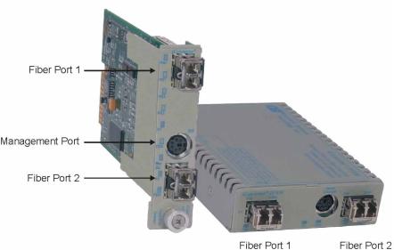
The front panel of the 2FXM provides access to the management (serial console) and fiber ports. The fiber ports are SFP supporting 100BASE-FX transceivers. The plug-in module features two additional Ethernet ports for connectivity via the chassis backplane.
2.1.1 |
Management Port |
|
|
|
PI |
|
SA |
The 2FXM features a Serial RS-232 Console Port (aka Craft Interface) which can be connected to a computer for initial setup and configuration. The Serial Console Port is accessed through the mini DIN-6 female DCE interface. Connect the interface to a computer’s DB-9 serial port using the mini DIN-6 male to DB- 9 female cable adapter (Part # 8082-0), which is included with the 2FXM.
An optional DB-9 male to female straight-through serial cable is available for extension (Part # 8081-3).
2.1.2 |
Fiber Ports |
|
|
|
PI |
|
SA |
The fiber interface supports the 100BASE-FX protocol. The fiber interface operates in manual mode and supports half or full duplex operation. The fiber port can be enabled or disabled via network management. A port disabled with the Port Access Control feature will still connect and allow 802.3ah OAM or IP-less (secure) OAM communication, but blocks normal data traffic.
2.1.3 |
Backplane Ethernet Ports |
|
PI |
The plug-in module supports two additional 10/100Mbps Ethernet Backplane Ports. The Backplane Ports A and B allow Ethernet data connectivity between adjacent modules in an iConverter chassis. The two backplane ports can be disabled or enabled via a DIP-switch or network management.
The iConverter 19-Module, 5-Module, 2-Module and 1-Module Redundant Chassis backplanes provide ethernet data connectivity between adjacent slots or ports. The A and B backplane ports connect the slots as illustrated.
Page 4

19-Module Chassis
5-Module Chassis |
2-Module Chassis |
1-Module Redundant Chassis
3.0INSTALLATION PROCEDURE
3.1OVERVIEW
The following steps outline the installation and configuration procedures for the 2FXM. Refer to the specified sections for detailed instructions.
•Configure DIP-switches (Section 3.2)
•Installing the Module and Connecting Cables (Section 3.3)
•Configure Module via Command Line Interface (Section 3.4)
•Verify Operation (Section 3.5)
When the setup and configuration procedures are completed, the 2FXM has been configured with the basic setup requirement for standard operation. To configure the module with additional features, see Section 4.0, “Detailed Module Configuration”.
Page 5
3.2 CONFIGURING DIP-SWITCHES PI 
 SA
SA
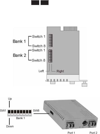
The 2FXM plug-in module has two board-mounted DIP-switches. The standalone unit has one bank of DIP-switches. The locations of the DIP-switches are illustrated on below.
|
DIP-switch Locations |
||||
3.2.1 |
Board-Mounted Bank 1 Settings |
|
|
|
|
PI |
|
SA |
|
||
DIP-switch Bank 1 is available on both the plug-in and standalone modules. The table indicates the position of the switch; Left/Down or Right/Up. As indicated in the DIP-switch location diagram, Left and Right refers to the plug-in module and Down and Up refers to the standalone module.
|
|
|
(Left/Right) |
|
|
(Up/Down) |
|
|
|
PI |
SA |
||||
|
|
|
|
|
|
|
|
Switch |
|
|
Left/Down |
|
|
Right/Up |
|
|
(Factory Default) |
|
|
||||
|
|
|
|
|
|||
SW1 |
Off: |
On: |
|||||
Pause Disable |
Pause Enable |
||||||
|
|||||||
SW2 |
FDX: |
HDX: |
|||||
Fiber Port 1Full-Duplex |
Fiber Port 1 Half-Duplex |
||||||
|
|||||||
SW3 |
Reserved |
Reserved |
|||||
SW4 |
Reserved |
Reserved |
|||||
SW5 |
FDX: |
HDX: |
|||||
Fiber Port 2 Full-Duplex |
Fiber Port 2 Half-Duplex |
||||||
|
|||||||
SW6 - SW8 |
|
See Link Mode DIP-Switch Table in Section 3.2.1.6 |
|||||
|
|
|
|
|
|
|
|
3.2.1.1SW1 - Pause Disable/Enable “Off/On”
When the Pause Enable DIP-switch is “Off” position (factory default), the 2FXM disables the fiber ports’ ability to send and receive Pause frames during network congestion. Setting this DIP-switch to the“On” position, enables the 2FXM to receive Pause frames from its link partner. This enables the 2FXM to stop
Page 6
transmitting traffic to its link partner and store incoming frames from the other port in the internal buffer until the congestion clears. If the internal buffer of the 2FXM becomes congested, it will transmit a Pause frame to its link partner.
3.2.1.2SW2 - Fiber Port 1 Full/Half-Duplex “FDX/HDX”
When the DIP-switch is in the Full Duplex “FDX” position (factory default), the fiber port will facilitate a connection that supports Full-Duplex operation. Setting this DIP-switch to Half-Duplex “HDX” facilitates a connection that supports only Half-Duplex.
3.2.1.3SW3, SW4 - Reserved
These DIP-switches are for factory use only.
NOTE: DIP-switches marked Reserved must be kept in the LEFT (factory default) position.
3.2.1.5SW5 - Fiber Port 2 Full/Half Duplex “FDX/HDX”
When the DIP-switch is in the Full Duplex “FDX” position (factory default), the fiber port will facilitate a connection that supports Full-Duplex operation. Setting this DIP-switch to Half-Duplex “HDX” facilitates a connection that supports only Half-Duplex.
3.2.1.6SW6, SW7, SW8 - Link Modes
These three DIP-switches configure the link mode settings. The following table details possible Link Mode DIP-switch configurations.
PI |
|
SA |
|
|
|
SW6 |
SW7 |
SW8 |
Result |
|
|
|
|
|
|
Left |
Left |
Left |
Enables Link Segment mode (LS). |
|
|
|
|
|
|
Right |
Left |
Left |
Enables Link Propagate mode (LP). |
|
|
|
|
|
|
Left |
Right |
Left |
Enables Remote Fault Detection mode plus |
|
Link Segment mode (RFD+LS). |
||||
|
|
|
||
Right |
Right |
Left |
Enables Remote Fault Detection mode plus |
|
Link Propagation mode (RFD+LP). |
||||
|
|
|
||
Left |
Left |
Right |
Enables Symmetrical Fault Detect mode (SFD). |
|
|
|
|
|
|
Right |
Left |
Right |
Illegal setting. LS mode is enabled. |
|
|
|
|
|
|
Left |
Right |
Right |
Illegal setting. LS mode is enabled. |
|
Right |
Right |
Right |
Illegal setting. LS mode is enabled. |
|
|
|
|
|
SW6 |
SW7 |
SW8 |
Result |
|
|
|
|
Down |
Down |
Down |
Enables Link Segment mode (LS). |
|
|
|
|
Up |
Down |
Down |
Enables Link Propagate mode (LP). |
|
|
|
|
Down |
Up |
Down |
Enables Remote Fault Detection mode plus |
|
|
|
Link Segment mode (RFD+LS). |
Up |
Up |
Down |
Enables Remote Fault Detection mode plus |
|
|
|
Link Propagation mode (RFD+LP). |
Down |
Down |
Up |
Enables Symmetrical Fault Detect mode (SFD). |
|
|
|
|
Up |
Down |
Up |
Illegal setting. LS mode is enabled. |
|
|
|
|
Down |
Up |
Up |
Illegal setting. LS mode is enabled. |
Up |
Up |
Up |
Illegal setting. LS mode is enabled. |
|
|
|
|
NOTE: Connecting two converters set to any of the RFD modes are illegal and will cause a “deadly embrace” lockup.
NOTE: It is recommended to keep the LS setting (default) until initial configuration is complete.
For detailed information on the operation of the different Link Modes, download the application note “iConverter Link Modes” available on Omnitron’s web page:
http://www.omnitron-systems.com/downloads.php
Page 7
3.2.2 |
Board-Mounted Bank 2 Settings |
|
PI |
DIP-switch Bank 2 is only available on the plug-in module.
Switch |
Left (Factory Default) |
Right |
SW1 |
A-DS: |
A-EN: |
|
Backplane Port A Disabled |
Port A Enabled |
SW2 |
B-DS: |
B-EN: |
|
Backplane Port B Disabled |
Port B Enabled |
SW3 |
Reserved |
Reserved |
SW4 |
M/SL: |
SL: |
|
Master/Slave Auto-Select |
Slave-Mode Only |
SW5 - SW8 |
Reserved |
Reserved |
3.2.2.1SW1 - Backplane Port A Enabled “A-DS/A-EN”
When the DIP-switch is in the Left “A-DS” position (factory default), Backplane Port A of the 2FXM is isolated from the chassis Backplane. When the DIP-switch is in the Right “A-EN” position, Backplane Port A of the 2FXM is enabled. This port allows Ethernet Backplane connectivity to an adjacent module via the chassis Backplane Port A. See the backplane illustrations in Section 2.1.3.
3.2.2.2SW2 - Backplane Port B Enabled “B-DS/B-EN”
When the DIP-switch is in the Left “B-DS” position (factory default), Backplane Port B is isolated from the chassis Backplane. When the DIP-switch is in the Right “B-EN” position, Backplane Port B is enabled. This port allows Ethernet Backplane connectivity to an adjacent module via the chassis Backplane Port B. See the backplane illustrations in Section 2.1.3.
3.2.2.3SW4 - Master/Slave Auto-Select and Slave-Only “M/SL / SL
When multiple management modules such as the iConverter NMM and the 2FXM (or multiple self-managed modules such as 2FXM) are installed in the same chassis, only one management module can act as the chassis master. The master management module has the ability to make changes to the settings of the other modules in the chassis, while the slave management modules cannot make the changes. If an NMM is installed in the chassis, the NMM will always be the master, otherwise the lowest slot number with a management module installed will become chassis master.
When this DIP-switch is in the Left “M/SL” position (factory default), the assignment of mastership is automatically negotiated by the installed management modules. To designate a specific management module as the master when no NMM is installed in the chassis, set the DIP-switch on the master module to the Left “M/SL” position, and set the other installed management modules’ DIP-switches to the Right “SL” position to enable Slave-Only mode.
Only the chassis master can change configuration settings of other modules.
3.2.2.4SW3, SW5, SW6, SW7, SW8 - Reserved
These DIP-switches are for factory use only.
NOTE: DIP-switches marked Reserved must be kept in the Left (factory default) position.
Page 8

3.3INSTALL MODULE AND CONNECT CABLES
PI
a.Carefully slide the module into an open slot in the chassis. Align the module with the installation guides and ensure that the module is firmly seated against the backplane. Secure the module by fastening the front panel thumbscrew (push in and turn clockwise to tighten) to the chassis front. Verify the “Pwr” LED is ON (indicating the chassis is powered).
SA
a.The 2FXM standalone Network Interface Device (NID) is available in tabletop and wall-mounting models. For wall-mounting, attach the NID to a wall, backboard or other flat surfaces. For tabletop installations, place the unit on a flat level surface. Attach the rubber feet to the bottom of the NID to prevent the unit from sliding. Make sure the unit is placed in a safe, dry and secure location.
To power the unit using the AC/DC adapter, connect the AC/DC adapter to the AC outlet. Then connect the barrel plug at the end of the wire on the AC/DC adapter to the 2.5mm DC barrel connector (center-positive) on the unit. Confirm that the unit has powered up properly by checking the power status LED located on the front of the unit.
To power the unit using a DC power source, prepare a power cable using a two-conductor insulated wire (not supplied) with a 14 AWG gauge minimum. Cut the power cable to the length required. Strip approximately 3/8 of an inch of insulation from the power cable wires. Connect the power cables to the 2FXM standalone unit by fastening the stripped ends to the DC power connector.
Connect the power wires to the DC power source. The Power LED should indicate the presence of power.
WARNING: Note the wire colors used in making the positive and negative connections. Use the same color assignment for the connection at the DC power source.
NOTE: If mounting with a safety ground attachment, use the safety ground screw at the rear of the unit.
PI 
 SA
SA
b.Insert the SFP Fiber transceivers into the Port 1 and Port 2 SFP receptacles on the 2FXM.
NOTE: The release latch of the SFP Fiber transceiver must be in the closed (up) position before insertion.
c.Connect the appropriate multimode or single-mode fiber cable to the fiber port of the installed module. It is important to ensure that the transmit (Tx) is attached to the receive side of the device at the other end and the receive (Rx) is attached to the transmit side. When using single-fiber (SF) media converter models, the Tx wavelength on one end has to match the Rx wavelength on the other. Based on this guideline, single fiber SFP fiber transceiver models must be used in pairs, such as the 7014-1 matched with the 7015-1.
NOTE: In order to support Remote OAM Management Mode, Port 1 of the 2FXM must be connected to the Port 1 on the 2FXM or link partner.
Page 9
3.4 CONFIGURE THE MODULE VIA COMMAND LINE INTERFACE PI 
 SA
SA
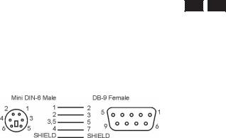
To configure, attach the 2FXM to a DB-9 serial (RS-232) equipped computer with terminal emulation software such as HyperTerminal. The 2FXM Serial Console Port (DCE) is a mini DIN-6 female connector which can be changed to a DB-9 connector with the included adapter (Part #8082-0). Attach the ends of a serial cable to the serial port of the PC and the Serial Console Port of the 2FXM. This is a standard asynchronous serial interface. The pin-outs are illustrated below.
Serial Connector Pin Outs
Start HyperTerminal and select the correct COM Port in the HyperTerminal “Connect To:” window. Set the PC’s serial port to the following:
Bits Per Second: |
57,600 |
Stop Bits: |
1 |
Data Bits: |
8 |
Parity: |
NONE |
Hardware Flow Control: |
NONE |
Power the chassis containing the 2FXM module and press <ENTER> to bring up a command line prompt on the attached PC.
The module is configured with the following defaults:
IP |
|
IP Address: |
192.168.1.220 |
IP Subnet Mask: |
255.255.255.0 |
Passwords |
|
Serial: |
No password assigned |
FTP: |
No password assigned |
Telnet: |
public |
SNMPv1/v2c Communities
READ: |
public |
|
|
WRITE: |
public |
|
|
SNMPv3 Parameters |
|
|
|
User 1 name (read only): |
guest |
|
|
User 2 name (read/write): |
admin |
|
|
User 1 Privacy pwd: |
publicguest |
User 1 Authen pwd: |
publicguest |
User 2 Privacy pwd: |
privateadmin |
User 2 Authen pwd: |
privateadmin |
Page 10
The Management Options screen will be displayed.
PI 
 SA
SA
Management Options |
iConverter, Serial Agent |
Network Management
1:Chassis and Module Management
2:Set Module Identifier
Management Module Preferences
3:IP and Control Preferences
4:SNMP Preferences
5:Abandon Preference Changes
6:Save Preference Changes
7:Restore to Factory Defaults
8:Restart Management Module
9:Other Networking Features
Management Module Maintenance
10:Firmware Update
11:Set Date/Time
IP Address |
= 192.168.1.220 |
Chassis Number = 1
Enter Choice, (H)elp, E(x)it >
A new 2FXM module does not have a password, and will skip the Password Entry screen and go straight to the Management Options screen. If a password has been set, the Password Entry screen will be displayed. Type the password and press <ENTER>, the 2FXM will respond with the Management Options screen.
PI 
 SA
SA
Omnitron Systems Technology, Inc. |
iConverter, Serial Agent |
Copyright 2001-2007 OST, Inc. |
Password Entry |
------------------------------------------------------------------------------
Omnitron Systems Technology |
Technical Support: |
(949) |
250-6510 |
140 Technology #500 |
Sales/Products: |
(800) |
675-8410 |
Irvine, CA 92618 |
On the web at: |
www.omnitron-systems.com |
|
------------------------------------------------------------------------------
IP Address 192.168.1.220
MAC 00:00:00:00:00:00
[xxxxxxxx]
Please enter the password >
Page 11

3.4.1Setting IP and Control Preferences
An IP address is required for the SNMP manager to address the 2FXM. The factory default setting is 192.168.1.220. The IP address can be configured manually or automatically as a DHCP client.
3.4.1.1Setting IP Parameters Manually
To manually configure the IP address and control parameters, select 3 from the Management Options screen. The IP and Control Preferences screen will appear.
PI |
|
SA |
|
|
|
|
|
||||
IP and Control Preferences Screen |
iConverter, Serial Agent |
||||
1: |
|
Set IP |
|
192.168.1.220 |
|
2: |
|
Set Subnet Mask |
255.255.255.0 |
||
3: |
|
Set Gateway |
192.168.1.1 |
||
4: |
|
Chassis Number |
1 |
||
5: |
|
Chassis Name (also sysName) |
2FXM |
||
6: |
|
Enable/Disable TELNET |
Enabled |
||
7: |
|
Enable/Disable FTP |
Disabled |
||
8: |
|
Enable/Disable Soft Switch Reload |
Disabled |
||
9: |
|
TELNET Password |
***** |
||
10: FTP |
Password |
|
|||
11: Serial Password |
|
||||
Enter Choice, Management Options Screen(0), (H)elp, E(x)it >
To configure the IP address of the 2FXM, select 1 at the IP and Control Preferences screen, and press <ENTER>. Backspace over the existing value, type the new value (in x.x.x.x format), and press <ENTER>.
To configure the subnet mask of the 2FXM, select 2 at the IP and Control Preferences screen, and press <ENTER>. Backspace over the existing value, type the new value (in x.x.x.x format), and press <ENTER>.
To configure the gateway of the 2FXM, select 3 at the IP and Control Preferences screen, and press <ENTER>. Backspace over the existing value, type the new value (in x.x.x.x format), and press <ENTER>.
To save the new values, select 0 and press <ENTER> to return to the Management Options screen, then select 6 and press <ENTER> to Save Preference Changes.
3.4.1.2Setting IP Parameters as DHCP Client
To configure the IP automatically as a DHCP client, select 9 from the Management Options screen. The
Other Networking Features screen will appear.
Page 12

PI 
 SA
SA
Management Options |
iConverter, Serial Agent |
Network Management
1:Chassis and Module Management
2:Set Module Identifier
Management Module Preferences
3:IP and Control Preferences
4:SNMP Preferences
5:Abandon Preference Changes
6:Save Preference Changes
7:Restore to Factory Defaults
8:Restart Management Module
9:Other Networking Features
Management Module Maintenance
10:Firmware Update
11:Set Date/Time
IP Address |
= 192.168.1.220 |
|
|||
Chassis Number = 1 |
|
||||
Enter Choice, (H)elp, E(x)it > 9 |
|
||||
|
|
|
|
|
|
|
|
|
|
|
|
PI |
|
SA |
|
|
|
|
|
||||
Other Networking Features Screen |
iConverter, Serial Agent |
||||
1: |
|
Enable/Disable DHCP Client |
Disabled |
||
2: |
|
Enable/Disable Keep Alive Trap |
Disabled |
||
3: |
|
Keep Alive Trap interval (10-600 secs) |
10 |
||
4: |
|
Enable/Disable SW1 Switch Block |
Enabled |
||
5: |
|
Serial Baud Rate |
57600 bps |
||
6: |
|
Enable/Disable VLAN Support |
Disabled |
||
7: |
|
VLAN ID (0-4095) |
2 |
||
8: |
|
VLAN Priority (0-7) |
7 |
||
Enter Choice, Management Options Screen(0), (H)elp, E(x)it >
To enable DHCP client, select 1 at the Other Networking Features screen and follow the screen prompts to enable DHCP.
To save the new values, select 0 and press <ENTER> to return to the Management Options screen, then select 6 and press <ENTER> to Save Preference Changes.
3.4.1.3Setting the Chassis Number and Name
A Chassis Name, or sysName, can be assigned for identification of the 2FXM in the SNMP client. The name can be any 1-32 character alphanumeric string.
The Chassis Number can remain as 1 (factory default) when the 2FXM is installed without an iConverter NMM in the same chassis. When the 2FXM is installed in the same chassis as an NMM, then the 2FXM must be set to the Chassis Number of the NMM.
To set the Chassis Number, select 4 at the IP and Control Preferences screen, press <ENTER> and follow the instructions to enter the chassis number.
To set the Chassis Name, select 5 at the IP and Control Preferences screen, press <ENTER> and follow the instructions to enter the chassis name.
Page 13

NOTE: When the NMM is installed into the chassis and is set to Remote OAM, the chassis number of the 2FXM is automatically assigned by the NMM.
PI |
|
SA |
|
|
|
|
|
||||
IP and Control Preferences Screen |
iConverter, Serial Agent |
||||
1: |
|
Set IP |
|
192.168.1.220 |
|
2: |
|
Set Subnet Mask |
255.255.255.0 |
||
3: |
|
Set Gateway |
192.168.1.1 |
||
4: |
|
Chassis Number |
1 |
||
5: |
|
Chassis Name (also sysName) |
2FXM |
||
6: |
|
Enable/Disable TELNET |
Enabled |
||
7: |
|
Enable/Disable FTP |
Disabled |
||
8: |
|
Enable/Disable Soft Switch Reload |
Disabled |
||
9: |
|
TELNET Password |
***** |
||
10: FTP |
Password |
|
|||
11: Serial Password |
|
||||
Enter Choice, Management Options Screen(0), (H)elp, E(x)it >
To save the new values, select 0 and press <ENTER> to return to the Management Options screen, then select 6 and press <ENTER> to Save Preference Changes.
3.4.1.4Setting 2FXM Passwords
The 2FXM is shipped from the factory without password protection on the Serial Console Port. It is highly recommended that the network administrator set a password in order to prevent unauthorized access to the unit. The password can be any 1-32 character alphanumeric string.
The 2FXM is shipped from the factory with Telnet enabled and FTP disabled. From the IP and Control Preferences screen, select 6 to enable or disable Telnet, and select 7 to enable or disable FTP.
To set the password for Telnet access, select 9 at the IP and Control Preferences screen, press <ENTER> and then follow the screen prompts to enter and verify the password. The default password for Telnet access is “public”.
To set the password for FTP access, select 10 at the IP and Control Preferences screen, press <ENTER> and then follow the screen prompts to enter and verify the password.
To set the password for serial access, select 11 at the IP and Control Preferences screen, press <ENTER> and then follow the screen prompts to enter and verify the password.
Page 14
Loading...