


 User’sGuide
Shop online at
www.omega.com e-mail: info@omega.com
PCL-3000 SERIES
High Accuracy Pressure Standard

|
OMEGAnet® Online Service |
|
Internet e-mail |
|
|
|
www.omega.com |
|
info@omega.com |
|
|
|
|
|
|
|
Servicing North America: |
||
USA: |
One Omega Drive, P.O. Box 4047 |
|
||
ISO 9001 Certified |
Stamford CT 06907-0047 |
|
||
|
|
TEL: (203) 359-1660 |
FAX: (203) 359-7700 |
|
|
|
e-mail: info@omega.com |
|
|
Canada: |
976 Bergar |
|
||
|
|
Laval (Quebec) H7L 5A1, Canada |
|
|
|
|
TEL: (514) 856-6928 |
FAX: (514) 856-6886 |
|
|
|
e-mail: info@omega.ca |
|
|
For immediate technical or application assistance:
USA and Canada: Sales Service: 1-800-826-6342 / 1-800-TC-OMEGA® Customer Service: 1-800-622-2378 / 1-800-622-BEST® Engineering Service: 1-800-872-9436 / 1-800-USA-WHEN® TELEX: 996404 EASYLINK: 62968934 CABLE: OMEGA
Mexico: |
En Espan˜ol: (001) 203-359-7803 |
e-mail: espanol@omega.com |
|
FAX: (001) 203-359-7807 |
info@omega.com.mx |
Servicing Europe:
Benelux: |
Postbus 8034, 1180 LA Amstelveen, The Netherlands |
|||
|
|
|
TEL: +31 (0)20 3472121 |
FAX: +31 (0)20 6434643 |
|
|
|
Toll Free in Benelux: 0800 0993344 |
|
|
|
|
e-mail: sales@omegaeng.nl |
|
Czech Republic: |
Frystatska 184, 733 01 Karviná, Czech Republic |
|||
|
|
|
TEL: +420 (0)59 6311899 |
FAX: +420 (0)59 6311114 |
|
|
|
Toll Free: 0800-1-66342 |
e-mail: info@omegashop.cz |
France: |
11, rue Jacques Cartier, 78280 Guyancourt, France |
|||
|
|
|
TEL: +33 (0)1 61 37 29 00 |
FAX: +33 (0)1 30 57 54 27 |
|
|
|
Toll Free in France: 0800 466 342 |
|
|
|
|
e-mail: sales@omega.fr |
|
Germany/Austria: |
Daimlerstrasse 26, D-75392 Deckenpfronn, Germany |
|||
|
|
|
TEL: +49 (0)7056 9398-0 |
FAX: +49 (0)7056 9398-29 |
|
|
|
Toll Free in Germany: 0800 639 7678 |
|
|
|
|
e-mail: info@omega.de |
|
United Kingdom: |
One Omega Drive, River Bend Technology Centre |
|||
ISO 9002 Certified |
Northbank, Irlam, Manchester |
|
||
|
|
|
M44 5BD United Kingdom |
|
|
|
|
TEL: +44 (0)161 777 6611 |
FAX: +44 (0)161 777 6622 |
|
|
|
Toll Free in United Kingdom: 0800-488-488 |
|
|
|
|
e-mail: sales@omega.co.uk |
|
It is the policy of OMEGA to comply with all worldwide safety and EMC/EMI regulations that apply. OMEGA is constantly pursuing certification of its products to the European New Approach Directives. OMEGA will add the CE mark to every appropriate device upon certification.
The information contained in this document is believed to be correct, but OMEGA Engineering, Inc. accepts no liability for any errors it contains, and reserves the right to alter specifications without notice.
WARNING: These products are not designed for use in, and should not be used for, patient-connected applications.
TABLE OF CONTENTS |
|
|
SECTION |
PAGE |
|
SECTION 1 INTRODUCTION ..................................................................... |
1 |
|
1.1 |
General Description ........................................................................................... |
1 |
1.2 |
Features ............................................................................................................... |
1 |
1.3 |
Options ................................................................................................................ |
1 |
SECTION 2 INSTALLATION ....................................................................... |
2 |
|
2.1 |
Unpacking ........................................................................................................... |
2 |
2.2 |
Mounting ............................................................................................................. |
2 |
2.3 |
117/220 Vac Operation ..................................................................................... |
2 |
2.4 |
Rear Panel Connections ..................................................................................... |
3 |
SECTION 3 OPERATION ............................................................................ |
4 |
|
3.1 |
Controls and Indicators ..................................................................................... |
4 |
3.2 |
Operating Procedure ......................................................................................... |
5 |
3.3 |
Configuration Switch Settings ......................................................................... |
6 |
3.3.1 |
ABS/Gage/Peak Hold Select ........................................................................... |
7 |
3.3.1.1 |
Freeze Mode ........................................................................................................ |
7 |
3.3.2 |
Convert Enable ................................................................................................... |
8 |
3.3.3 |
Digital Averaging ............................................................................................... |
8 |
3.3.4 |
Automatic Zero Maintenance (AZM) Enable ................................................ |
8 |
3.3.5 |
Automatic Span Maintenance (ASM) Enable ................................................ |
9 |
SECTION 4 THEORY OF OPERATION ......................................................... |
9 |
|
SECTION 5 CALIBRATION ....................................................................... |
10 |
|
5.1 |
General ................................................................................................................ |
10 |
5.2 |
Calibration Set-Up ........................................................................................... |
10 |
5.3 |
Instrument Set-Up ............................................................................................ |
10 |
5.4 |
Zero/Span Calibration (Each Range) ............................................................ |
11 |
5.5 |
Linearity and Hysteresis Calibration (Each Range) .................................... |
12 |
5.6 |
Shunt Resistor Calibration .............................................................................. |
13 |
5.7 |
Permanent Data Storage .................................................................................. |
14 |
SECTION 6 SPECIFICATIONS ................................................................... |
14 |
|
i
SECTION 1 INTRODUCTION
1.1GENERAL DESCRIPTION
The OMEGA® PCL-3000 Series Digital Pressure Standards are specifically designed for use in the manufacture, test or calibration of pressure sensitive devices. Using a patented, bonded foil strain gage sensor and advanced microcircuitry these rugged, compact instruments provide simultaneous digital and analog readouts of the pressures applied.
Standard front panel switches permit desired pressure range selection, automatic zeroing of the display, and actuation of a unique internal self-calibration feature.
Each instrument has two displays - digital and analog. The digital display provides precise pressure information, and the analog display gives quick reference to direction and level of pressure.
1.2FEATURES
•Three, independent, switch selectable pressure ranges per instrument
•Accuracy of each range equal to or better than +0.5% F. S.
•Both GAGE and ABSOLUTE pressure calibrations available via front panel switch selection (for applicable models)
•Automatic Self-Calibration: Computer controlled internal circuitry provides automatic maintenance of both zero and span calibration data to insure long term stability and accuracy. No potentiometer adjustments used or required. Calibration of all three ranges completed within six seconds.
•Calibration Integrity: Tamper-proof design. Once calibrated, numerous “safe guards” guarantee the integrity of pressure readings obtained. Display “prompting” provides operator with functional status information during both operation and calibration.
•Digital Display: Eliminates parallax, interpolation and operator judgement errors. Large, bright red LED digits provide excellent readability under all lighting conditions.
•Analog Display: An electronic, front panel meter provides instantaneous visual indication of applied pressure.
•Fast response - pressure data refreshed 10 times per second
•Pressure media - any gas or fluid compatible with 17-4PH stainless steel alloy
•Data output is Serial data, 20 mA loop current, ASCII code, supplied as standard interface
1.3OPTIONS
ANALOG OUTPUT:
Either a 0 to 10 Vdc or a 4 to 20 mA isolated output is available. Both outputs are optically isolated from the input circuitry and the external case. The accuracy is ±0.25% F. S. maximum.
PARALLEL BCD DATA OUTPUT:
This output is isolated, tri-state buffered and DTL/TTL compatible. The data consists of; polarity, five full data digits, measurement units, data valid, hold and enable lines.
RS-232 SIMPLEX OUTPUT:
Available with BAUD Rate Select from 300 to 9600 BAUD, two different formats -computer or printer; and two different request modes - demand or continuous. A program sheet is supplied by the factory when this option is ordered.
PEAK HOLD:
This option retains the maximum pressure value in memory. Depressing the RECALL switch on the front panel will display the peak reading. Depressing the RESET switch clears the peak reading register.
SETPOINT OUTPUT:
Up to two independent set points can be programmed and provided for the purpose of implementing various control functions. These set points may be programmed or changed either via internal switch settings or by the operator.
Solid state, optically isolated relay output contacts rated at 120/240 Vac and 1.5 A are provided for control. Relays may be programmed to be either OPEN or CLOSED below the set point activation level.
BATTERY OPERATION:
This internal self-contained rechargeable battery provides eight hours of continuous service. A low battery light (lower righthand corner of front panel) indicates when it’s time to recharge the batteries.
PANEL MOUNTING KIT: This optional side-mounting kit allows recessed mounting into a custom fit panel.
FREEZE MODE:
When connected via terminal board, TB-2 pins 7 and 8, display data will be momentarily (approximately 5 seconds) frozen when external switch contacts change state
1

SECTION 2 INSTALLATION
2.1UNPACKING
Remove the Packing List and check off actual equipment received. If there are any questions about the shipment, please call the OMEGA Customer Service Department at 1-800-622-2378 or (203) 359-1660. We can also be reached on the Internet at:
www.omega.com e-mail: info@omega.com
Upon receipt of shipment, inspect the container and equipment for any signs of damage. Take particular note of any evidence of rough handling in transit. Immediately report any damage to the shipping agent.
NOTE:
The carrier will not honor any claims unless all shipping material is saved for their examination. After examining and removing contents, save packing material in the event reshipment is necessary.
2.2MOUNTING
The PCL-3000 Series comes standard for table-top usage, with rubberized feet and a tilt stand. With the optional Panel Mounting Kit, the PCL-3000 can be panel-mounted through panels of any thickness up to 11⁄4 inches. Panel cutout dimensions and overall unit dimensions are shown in Figure 2-1.
2.3117/220 VAC OPERATION
The PCL-3000 is supplied with a multi-tap power transformer primary winding such that input voltages of 117 Vac or 220 Vac, 50/60 Hz may be used for excitation.
The unit will be shipped from the factory with the voltage set according to the customer order, and the 0PCL-3000’s rear panel nameplate will reflect this voltage.
To change the operational voltage:
1.Loosen the two thumbscrews located at the bottom outermost corners of the front panel, then slide the electronic assembly forward.
NOTE:
The PCL-3000 may be fully operated with the case removed without any potentially lethal shock hazard to operating personnel, since the highest accessible internal voltage is nominally 25 Vdc.
2.Remove the two screws which hold the line voltage filter to the rear panel. Leave all the wires connected and simply fold them out of the way temporarily.
3.Carefully remove and save the protective insulating cover sheet from the top of the transformer.
4.Refer to Figure 2-2 and make the appropriate transformer connections via jumpers.
2
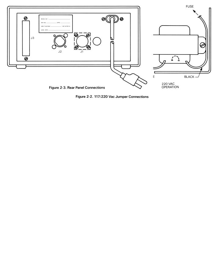
2.4REAR PANEL CONNECTIONS
The rear panel (refer to Figure 2-3) contains the power line input receptacle, the pressure port fitting, the unit’s identification plate, and if required, either one or both option connectors, J1 and J3. The J1 connector is for either of the Analog Output options and the RS-232 option. The J3 connector is for the Parallel BCD Output option. The pressure port is a male, 7/16-20 UNF-2A fitting.
3

SECTION 3 OPERATION
NOTE:
Some configurations require that certain switches be inactive. For example, the ABS/GAGA switch is not required if the unit is configured for “gage only” operation. If so, the affected switch will be internally programmed to be inactive and a “blank” overlay will be used to cover the switch nomenclature.
4
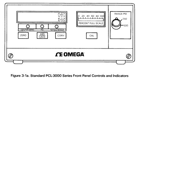
3.2OPERATING PROCEDURE
1.Apply power to the instrument and allow to stabilize for at least 20 minutes. If possible, the unit should have power applied continuously.
2.Connect the pressure source to the instrument via the male, 7/16-20 UNF-2A fitting provided on the rear panel. Valves for venting and applying the pressure should be provided.
3.Select the desired full scale pressure range via the three position RANGE-PSI Switch. Do not change pressure ranges during any given pressure cycle.
4.If applicable or required, select the GAGE mode of operation by momentarily depressing the ABS/GAGE push button switch.
5.To zero the instrument, vent the input pressure port to atmosphere (0 PSIG) and momentarily depress the ZERO push button switch.
The display will indicate “zero” and the CENTER ZERO annunciator (LED) will illuminate.
5
6.To perform a self-calibration check simply set the instrument to zero as per step 5 and momentarily depress the CAL switch.
The display will immediately blank except for two “- -” which indicate the unit is performing the selfcalibration. If the calibration is correct, a 100.00 indication will be momentarily displayed and then the display will revert to its normal “zero” indication.
7.To select the desired measurement display units (psi, % full scale, or inches H20) depress the CONV push button switch.
8.The instrument is now fully calibrated and ready to display applied pressure.
CAUTION:
Application of pressures greater than 1.5 times the highest pressure range value of the indicator may cause calibration errors or even permanent damage to the pressure transducer.
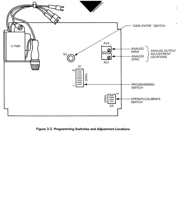
3.3CONFIGURATION SWITCH SETTINGS
As normally supplied, the PCL-3000 will be fully calibrated and configured to the requirements specified by the customer. However, there are several functions or operational features (covered in paragraphs 3.3.1 through 3.3.5) that may be altered by the operator during usage. These are controlled by the eight position DIP switch, S1 (refer to Figure 3-2). To access S1, loosen the two thumbscrews located at the bottom outermost corners of the front panel, then slide the electronic assembly forward.
6
 Loading...