


OS523E
Omega OS523E, OS53xE-CF, OS532E, OS524E, OS533E User Manual
...
OS530LE, OS532E, OS53xE-CF,
OS533E, OS534E, OS530HRE,
OS523E, OS524E OMEGASCOPE
®
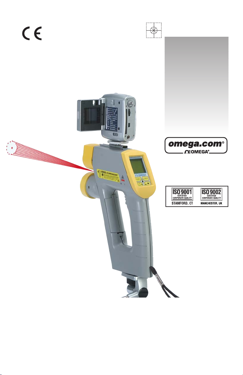
Handheld Infrared Thermometer
Shown with
Built-in Distance
Measuring Option
and Digital Video
Camera Attachment
TM
omega.com
e-mail: info@omega.com
For latest product manuals:
omegamanual.info
User’s Guide
Shop online at

Servicing North America:
U.S.A.: One Omega Drive, Box 4047
ISO 9001 Certified Stamford, CT 06907-0047
Tel: (203) 359-1660
FAX: (203) 359-7700
e-mail: info@omega.com
Canada: 976 Bergar
Laval (Quebec) H7L 5A1, Canada
Tel: (514) 856-6928
FAX: (514) 856-6886
e-mail: info@omega.ca
For immediate technical or application assistance:
U.S.A. and Canada: Sales Service: 1-800-826-6342/1-800-TC-OMEGA
®
Customer Service: 1-800-622-2378/1-800-622-BEST
®
Engineering Service: 1-800-872-9436/1-800-USA-WHEN
®
Mexico: En Espan˜ol: (001) 203-359-7803
e-mail: espanol@omega.com
FAX: (001) 203-359-7807
info@omega.com.mx
Servicing Europe:
Czech Republic: Frystatska 184, 733 01 Karvina´, Czech Republic
Tel: +420 (0)59 6311899
FAX: +420 (0)59 6311114
Toll Free: 0800-1-66342
e-mail: info@omegashop.cz
Germany/Austria: Daimlerstrasse 26, D-75392 Deckenpfronn, Germany
Tel: +49 (0)7056 9398-0
FAX: +49 (0)7056 9398-29
Toll Free in Germany: 0800 639 7678
e-mail: info@omega.de
United Kingdom: One Omega Drive, River Bend Technology Centre
ISO 9002 Certified Northbank, Irlam, Manchester
M44 5BD United Kingdom
Tel: +44 (0)161 777 6611
FAX: +44 (0)161 777 6622
Toll Free in United Kingdom: 0800-488-488
e-mail: sales@omega.co.uk
OMEGAnet®Online Service Internet e-mail
omega.com info@omega.com
It is the policy of OMEGA Engineering, Inc. to comply with all worldwide safety and EMC/EMI
regulations that apply. OMEGA is constantly pursuing certification of its products to the European New
Approach Directives. OMEGA will add the CE mark to every appropriate device upon certification.
The information contained in this document is believed to be correct, but OMEGA accepts no liability for any
errors it contains, and reserves the right to alter specifications without notice.
WARNING: These products are not designed for use in, and should not be used for, human applications.

Unpacking Instructions
n4
Notes

Unpacking Instructions
Remove the Packing List and verify that you have received all
equipment, including the following (quantities in parentheses):
• OS530/OS520 Series Handheld Infrared Thermometer (1)
• AA Size Lithium Batteries (4)
• Soft Cover Carrying Case (1)
• Analog Cable (1)
• RS232 Cable (only for OS533E, OS534E, OS523E, OS524E)
• CD Software (only for OS533E, OS534E, OS523E, OS524E)
• Quick Start Manual (1)
Accessories
If you have any questions about the shipment, please call Customer
Service at:
1-800-622-2378 or 203-359-1660. We can also be reached on the
Internet at:
omega.com
e-mail: cservice@omega.com
When you receive the shipment, inspect the container and equipment
for signs of damage. Note any evidence of rough handling in transit.
Immediately report any damage to the shipping agent.
The carrier will not honor damage claims unless all shipping
material is saved for inspection. After examining and removing
contents, save packing material and carton in the event
reshipment is necessary.
Model No. Description
UNI-ADAP-9V 100-240 Vac adapter, 9 Vdc @1.7A
OS520-RCC Hard Carrying Case, Standard
OS520-SC-RCC Hard Carrying Case, Large
88013K Surface Probe, K Type T/C, up to 815°C (1500°F)
88001K Surface Probe, K Type T/C, up to 482°C (900°F)
CAL-3-IR NIST Traceable Calibration
SC-520 Sighting Scope
HH-DM Distance Measuring Meter
DV-CAM Digital/Video Camera
NOTE
i

ii

TABLE OF
CONTENTS
Page
Unpacking Instructions i
Chapter 1 General Description 1-1
1.1 Introduction 1-1
1.2 Parts of the Thermometer 1-5
1.2.1 Front of the Thermometer 1-5
1.2.2 Rear of the Thermometer 1-7
Chapter 2 Using the Handheld Infrared Thermometer 2-1
2.1 How to Power the Thermometer 2-1
2.1.1 Battery Operation 2-1
2.1.2 AC Power Operation 2-1
2.2 Operating the Thermometer 2-2
2.2.1 Measurement Techniques 2-6
2.3 Real Time Mode (Active Operation) 2-8
2.3.1 Adjusting Emissivity 2-11
2.3.2 Using the LOCK Function 2-11
2.3.3 Using the Trigger Function 2-11
2.3.4 Using the Distance Function 2-12
2.3.5 Laser Sighting Status 2-15
2.3.6 Calculating Temperature Values 2-15
2.3.7 Changing the Temperature from °F to °C (or vice versa) 2-16
2.3.8 Turning on the Display Backlighting 2-16
2.3.9 Thermocouple Input (OS532E, OS533E, OS534E) 2-16
2.3.10 Using the Alarm Functions 2-17
2.3.11 Using Ambient Target Temperature Compensation 2-19
(OS533E, OS534E, OS523E, OS524E)
2.3.12 PC Interface Software (OS533E, OS534E, OS523E, OS524E) 2-20
2.3.13 PC Interface Commands 2-25
2.3.14 Storing Temperature Data on Command 2-27
(OS533E, OS534E, OS523E, OS524E)
2.3.15 Logging Temperature Data in Real Time 2-28
(OS533E, OS534E, OS523E, OS524E)
2.3.16 Erasing the Temperature Data from Memory 2-29
2.4 Recall Mode (Passive Operation) 2-30
2.4.1 Reviewing the Last Parameters 2-32
2.4.2 Reviewing Previously Stored Temperature Data 2-32
(OS534E, OS523E, OS524E)
Chapter 3 Laser Sighting 3-1
3.1 Warnings and Cautions 3-1
3.2 Description 3-2
3.3 Operating the Laser Sighting 3-3
3.4 Laser Sighting Status 3-3
Chapter 4 Sighting Scope 4-1
4.2 Installing and Operating the Sighting Scope 4-1
OS530E/OS520E Series
Handheld Infrared Thermometer
iii

iv
Chapter 5 Digital Video Camera 5-1
5.1 Camera Parts 5-1
5.2 Battery Installation 5-1
5.3 Turning Camera ON/OFF 5-1
5.4 Menu Selection 5-1
Chapter 6 Maintenance 6-1
6.1 Replacing the Batteries 6-1
6.2 Cleaning the Lens 6-2
6.3 Calibrating the Thermometer 6-2
6.4 Servicing the Laser Sighting 6-2
Chapter 7 Troubleshooting Guide 7-1
Chapter 8 Specifications 8-1
Chapter 9 Glossary of Key Strokes 9-1
Appendix A How Infrared Thermometry Works A-1
Appendix B Emissivity Values B-1
Appendix C Determining an Unknown Emissivity C-1
Index I-1
TABLE OF
CONTENTS

1-1
General Description
1
1.1 Introduction
The OS530E/OS520E series Handheld Infrared (IR) Thermometers
provide non-contact temperature measurements up to 4500°F. They
offer effective solutions for many non-contact temperature
applications, including the following:
• Predictive Maintenance: Tracking temperature shifts which
indicate pending failure in solenoid valves.
• Energy Auditing: Locating wall insulation voids to reduce
building heating costs.
• Food Processing: Taking accurate temperature readings without
direct contact with the food or packaging material.
The IR thermometer provides information at a glance — the custom
backlit dual digital LCD displays both current and minimum,
maximum, average or differential temperatures. This versatile
instrument provides:
• Measurable target distances from 5 inches to approximately 100
feet
• Emissivity adjustable from 0.1 to 1.00 in 0.01 steps provides ease
of use when measuring a variety of surfaces.
• Built-in Laser sighting in Circle & Dot configurations.
• Thermocouple input available.
• Distance Measurement available, either field mountable or builtin.
• Digital/Video Camera Option available
• An electronic trigger lock feature set via the keypad allows
continuous temperature measurement up to 10 times per second.
• Audible and visual alarms. The high and low alarm points
are set via the keypad.
• 1 mV per degree (°F or °C) analog output, which allows
interfacing with data acquisition equipment (including
chart recorders, dataloggers and computers). OS524E provides 0.5
mV/Deg.
• Last temperature recall (Hold).
• Backlit display useful in low ambient light conditions.
• Powers from 4 AA size batteries or an ac adapter.
• RS232 serial communication to a PC or printer. This allows
downloading data for further analysis.
• Ambient target temperature compensation. This provides more
accuracy for measuring low emissivity targets.
• Record up to 800 temperature data points. Review the recorded
data on the thermometer LCD, as well as downloading the data
to a PC.

General Description
1
1-2
The thermometer is easy to use:
• Units have standard “V” groove aiming sights.
• Integral tripod mount permits hands-free operation, if necessary.
• Temperature readings are switchable from °F to °C via the keypad.
• Parameters, such as target material emissivity and alarm setpoints, can
be set and remain in memory until reset.
This instrument has a rugged and functional design, including:
• Sealed keypad display.
• Convenient trigger operation.
• Soft carrying case and wrist strap, for safety and ease of carrying.
• Rubber boot around the lens and the display.
Table 1-1. OS530 Series Handheld Infrared Thermometer Features
Features
OS530LE OS532E OS533E OS534E
Accuracy* ±1% rdg ±1% rdg ±1% rdg ±1% rdg
Range -10 to 1000°F -10 to 1000°F -10 to 1000°F -10 to 1600°F
-23 to 538°C -23 to 538°C -23 to 538°C -23 to 871°C
Emissivity adjustable adjustable adjustable adjustable
Backlit Dual Display standard standard standard standard
Distance to Spot
Size Ratio 10:1 10:1 20:1 30:1
Differential Temperature standard standard standard standard
Min/Max Temperature standard standard standard standard
Average Temperature standard standard standard standard
High Alarm standard standard standard standard
Thermocouple Input — standard standard standard
Audible Alarm
& Indicator standard standard standard standard
Analog Output 1mV/deg 1mV/deg 1mV/deg 1mV/deg
Built-in Laser Sighting dot/circle dot/circle dot/circle dot/circle
Trigger Lock standard standard standard standard
Last Temperature Recall standard standard standard standard
Low Alarm — — standard standard
Ambient Target
Temperature — — standard standard
Compensation
RS232 Interface — — standard standard
Data Storage — — — standard
Distance Measurement Optional
Digital Camera Optional

1-3
General Description
1
Features
OS530HRE OS530LE-CF OS533E-CF OS534E-CF
Accuracy* 3°F (1.7 °C) ±1% rdg ±1% rdg ±1% rdg
Range -22 to 250°F -10 to 1000°F -10 to 1000°F -10 to 1600°F
-30 to 121°C -23 to 538°C -23 to 538°C -23 to 871°C
Emissivity Adjustable Adjustable Adjustable Adjustable
Display Resolution 0.1°For 0.1°C 1°F or 1°C 1°F or 1°C 1°F or 1°C
Backlit Dual std std std std
Display
Field of view 20:1 0.15"@6" 0.15"@6" 0.15"@6"
Differential
Temperature std std std std
Min/Max
Temperature std std std std
Average
Temperature std std std std
High Alarm std std std std
Low Alarm --- --- std std
Audible Buzzer
& Indicator
std std std std
Ambient Target
Temp --- --- std std
Compensation
Analog Output 1 mV/Deg 1 mV/Deg 1 mV/Deg 1 mV/Deg
RS232 Output --- --- std std
Data Storage --- --- --- std
Built-in Laser Dot/Circle Dot Dot Dot
sighting
Trigger Lockstd std std std std
Last Temperature
Recall std std std std
Thermocouple
Input --- --- std std
Distance Optional Not Recommended
Measurement
Digital Optional
Camera
* The temperature accuracy is 1% of Rdg or 2ºC (3ºF) whichever is greater.

General Description
1
1-4
Distance to Spot Size Ratio
OS523E-1 30:1
OS523E-2 60:1
OS523E-3 68:1
** OS523E provides three field of views:
Features OS523E
**
OS524E
Accuracy ±1% rdg ±1% rdg
Range 0 to 2500°F 1000 to 4500°F
(-18 to 1371°C) (538 to 2482°C)
Emissivity adjustable adjustable
Backlit Dual Display standard standard
Distance to Spot Size Ratio varies** 110:1
Differential Temperature standard standard
Min/Max Temperature standard standard
Average Temperature standard standard
High Alarm standard standard
Low Alarm standard standard
Audible Alarm & Indicator standard standard
Ambient Target
standard standard
Temperature Compensation
Analog Output 1 mV/deg 0.5 mV/deg
RS-232 Output standard standard
Thermocouple Input ––– –––
Data Storage standard standard
Built-in Laser Sighting dot/circle dot/circle
Trigger Lock standard standard
Last Temperature Recall standard standard
Distance Measurement Optional
Digital Camera Optional
1.2 Parts of the Thermometer
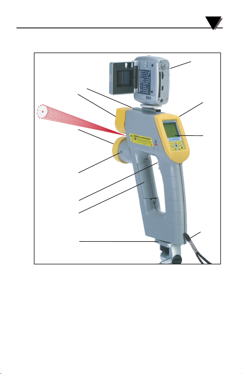
1.2.1 Front of the Thermometer
Figure 1-1. OS530E/OS520E Series Handheld Infrared Thermometer Front View
The display is shown in more detail in Figure 1-2 and described in Table 1-2.
There are no user-serviceable parts in the thermometer.
Refer to Chapter 3 for Laser Sight information.
“V” Groove
Lens Rubber
Boot
Built-in
Distance Module
(Optional)
Distance
Powe r
Switch
Trigger
Battery
Compartment
Door
Tripod
Mount
Digital/Video
Camera
(Optional)
Display
Rubber
Boot
Backlit
LCD
Wrist
Strap
1-5
General Description
1
General Description
1
1-6
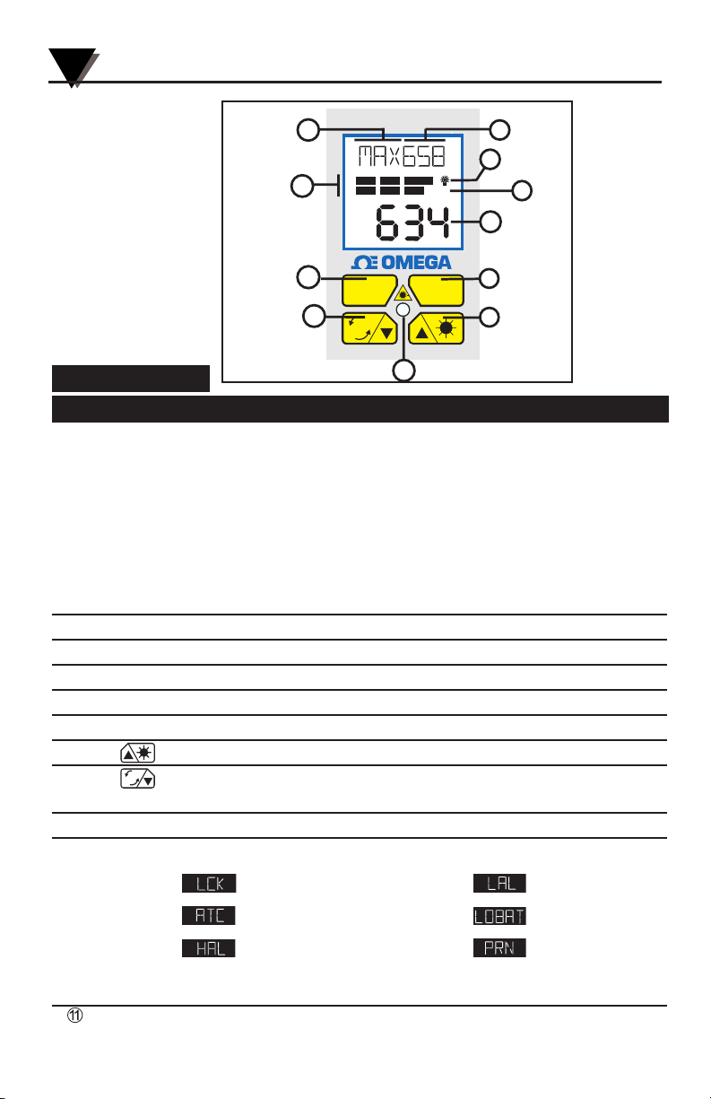
Figure 1-2.
Display and
Keypad View
Table 1-2. Display Details
Key Description
➀
Display Mode displays one of the following:
E (Emissivity) AVG (Average Temperature)
d_F (distance in Feet) HAL (High Alarm Setpoint)
d_M (Distance in Meters) TC (Thermocouple Input)
LSR (Laser either flashing or continuous) LAL (Low Alarm Setpoint)
MAX (Maximum Temperature) AMB (Ambient Target Temp)
MIN (Minimum Temperature) PRN (Send Data to PC)
dIF (Differential Temperature) MEM (Store Individual Temperature Data)
LOG (Log Temperature Data)
➁
Data associated with one of the Display Modes
➂
Backlighting Icon - allows the display to be viewed under low ambient light
➃
Displays the units of measure in either °F or °C
➄
Main display - displays the current temperature
➅
Locks the trigger / Enables or Disables alarms/Resets MAX, MIN, Dif, Avg. Temps
➆
for incrementing data; and is for turning on/off the display backlighting
➇
for decrementing data; and is for changing the units of measure from °F to °C or vice
versa
➈
Function key for scrolling through the display modes
➉
Display Icons
Trigger Lock Low Alarm
Ambient Target Low Battery
High Alarm Data Transfer thru
RS232
Laser Power Indicator LED
F
C
FUNC LOCK
®
F
C
OMEGASCOPE
®
LCK
HAL
LOBAT
ATC
LAL
PRN
°F °C
1
11
10
9
8
7
6
5
4
3
2
1-7
General Description
1
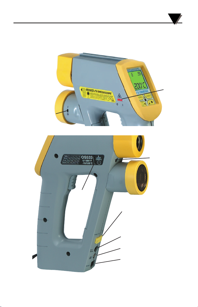
Figure 1-3 shows the various jacks for analog output, thermocouple input
and the ac adapter to the thermometer. The figures also show the location of
the Laser Power Switch, Dot-Circle Switch, and Laser Beam Aperture. More
details are provided in Section 2.2.1.
Figure 1-3. OS530E/OS520E Series Handheld Infrared Thermometer
Various Views
Laser
Dot/Circle
Switch
Laser
Power
Switch
Distance
Power
Switch
Laser Beam
Aperture
Thermocouple Input
Socket (SMP)
(standard on OS532E,
OS533E, OS534E)
ac Adapter Input Jack
Analog Output Jack (1mV/deg)
RS-232 Phone Jack
(standard on OS533E,
OS534E, OS523E, OS524E)

General Description
1
1-8
Notes
2-1
Using the Handheld Infrared Thermometer
2
2.1 How to Power the Thermometer
2.1.1 Battery Operation
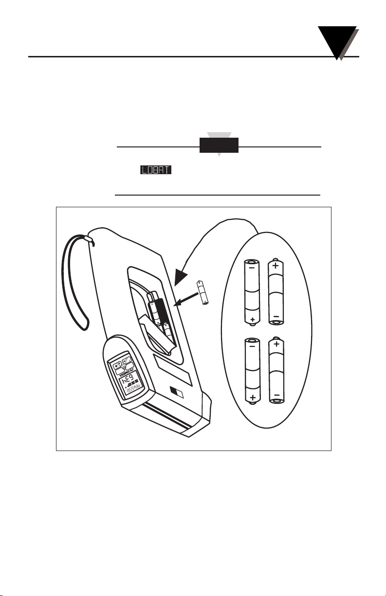
Invert the thermometer and install 4 fresh AA size batteries as shown in
Figure 2-1. Make sure the batteries’ polarities are correct, the batteries are
not put in backwards, and are of the same type.
If the icon flashes, the batteries must be
replaced with fresh batteries immediately.
Figure 2-1. Installing the Batteries
2.1.2 ac Power Operation
The thermometer may be operated on ac power using the optional
universal 100/240 Vac adapter. When operating on ac power the batteries
supply backup power in case of ac power failure. The ac adapter input jack
is shown in Figure 1-3.
NOTE
C
F
FU
NC LOC
K
®
A
TC
LC
LAL
K
H
PR
A
L
N
°
L
F
O
°
B
C
A
T
OME
G
A
S
COPE
®
Using the Handheld Infrared Thermometer
2
2-2
2.2 Operating the Thermometer
1a. (Without the Laser Sighting) -Aim the thermometer at the target to
be measured. Use the “V” groove (shown in Figure 1-1) on top of
the thermometer to align the target to the thermometer’s field of
view. Look down the “V” groove with one eye only, in order to
guarantee proper sighting. Pull and hold the trigger.
1b. (With the Laser Sighting) - Set the laser power switch to the
ON position. Aim at the target and pull the trigger. The laser
beam and the red power indicator LED will turn on while the
trigger is pulled. Refer to Chapter 3 for more details on the Laser
Sighting.
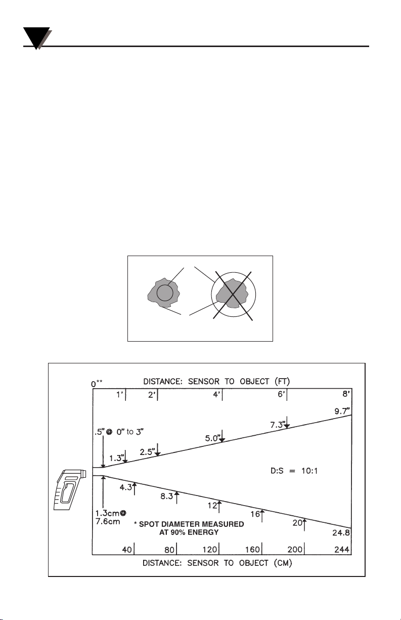
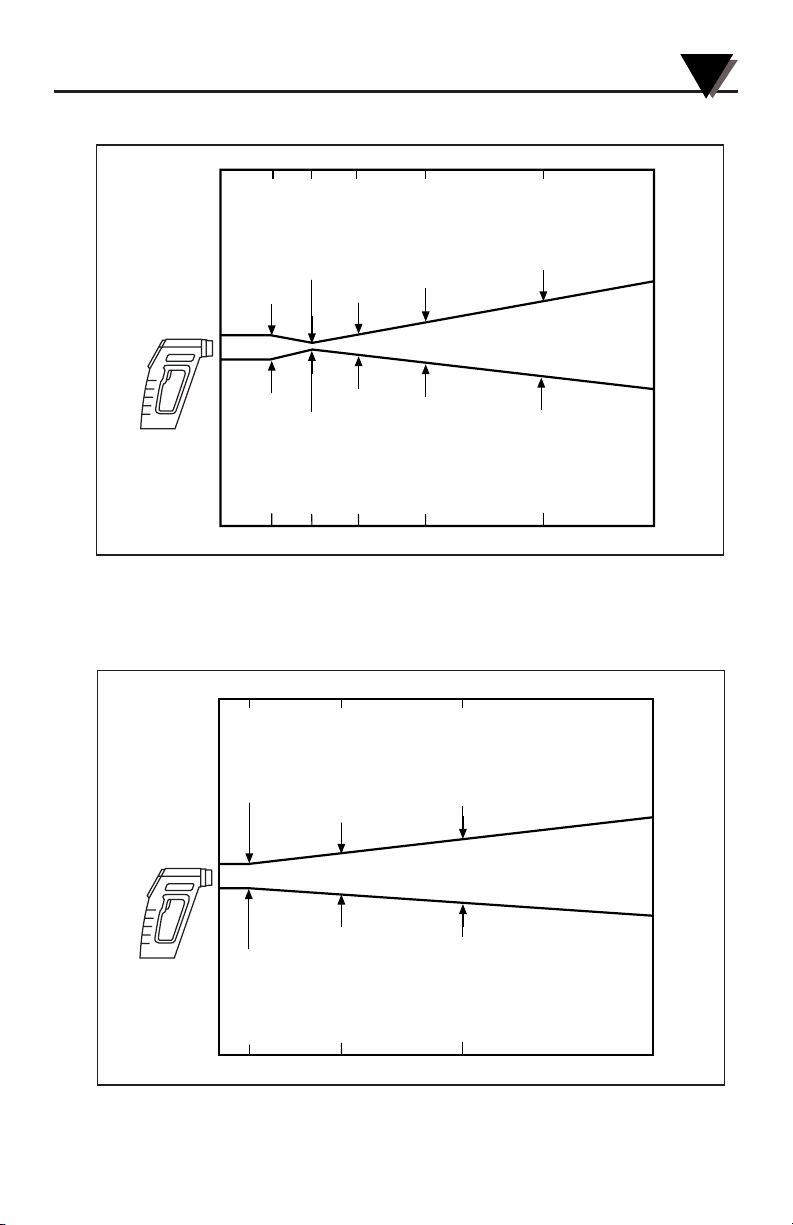
2. The field of view of the thermometer should fall within the area
of the target being measured as shown in Figure 2-2. Figures 2-3
through 2-9 show the field of view vs distance for the various
thermometers.
Figure 2-2. Field of View Positions
Figure 2-3. Field of View OS532E, OS530LE
SPOT DIA. * (IN)
SPOT DIA. * (CM)
Field of View
Target
(ACCEPTABLE)
(UNACCEPTABLE)
2-3
Using the Handheld Infrared Thermometer
2
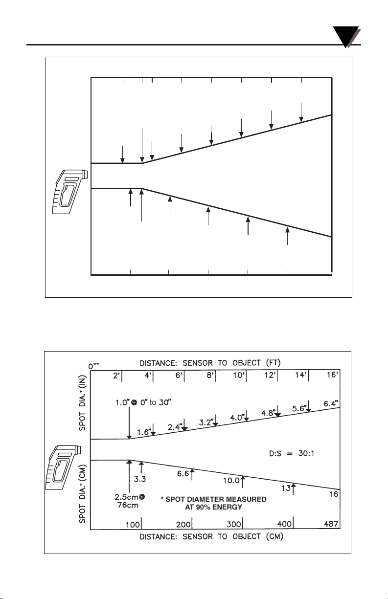
** Measurement distance is from the outside surface of the rubber boot.
4.8"
1.0" @ 0" to 20"
2.5cm @ 51cm
1.2"
1.0"
2.5
6.0
4.0
8.0
10.0
12.2
1601208040
1.0"
1.8"
2.4"
3.0"
3.6"
4.2"
1' 2'
200
8'6'
0**
DISTANCE: SENSOR TO OBJECT (FT)
DISTANCE: SENSOR TO OBJECT (CM)
SPOT DIA.* (IN)SPOT DIA.* (CM)
*SPOT DIAMETER MEASURED
AT 90% ENERGY
D:S = 20:1
4'
244
3' 5' 7'
20"
Figure 2-5 Field of View OS534E, OS523E-1
Figure 2-4 Field of View OS533E, OS530HRE
Using the Handheld Infrared Thermometer
2
2-4
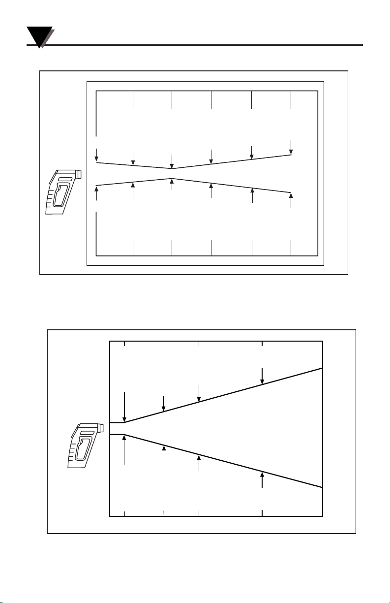
Figure 2-7 Field of View OS523E-2
Figure 2-6 Field of View OS53xE-CF
DISTANCE: SENSOR LENS TO OBJECT (in.)
0
3"
6"
9"12"
15"
SPOT DIA.* (IN)
0.9"
22
0
SPOT DIA.* (MM)
.45"
11.5
*SPOT DIAMETER MEASURED
AT 90% ENERGY
7.6
0'
0.9"@ 0
SPOT DIA.* (IN)
0.9"
30.5
.78"
D:S = 40:1
19.9
38.1
1.9"
.15"
3.9
15.2
DISTANCE: SENSOR LENS TO OBJECT (cm.)
DISTANCE: SENSOR TO OBJECT (FT)
3'
1.0"
.39"
9.9
22.9
5'
1.2"
1.17"
29.9
16'10'
2.9"
26
22mm @ 0
*SPOT DIAMETER MEASURED
AT 90% ENERGY
0
SPOT DIA.* (MM)
1.0 3.01.5
31
DISTANCE: SENSOR TO OBJECT (M)
D:S = 60:1
48
75
5.0
2-5
Using the Handheld Infrared Thermometer
2
Figure 2-8 Field of View OS523E-3
Figure 2-9 Field of View OS524E
DISTANCE: SENSOR TO OBJECT (FT)
0’
3’
16’10’2’ 5’
SPOT DIA.* (IN)
SPOT DIA.* (MM)
.35"@ 24"
.8"
21
9mm @ 610mm
*SPOT DIAMETER MEASURED
0
.9"
AT 90% ENERGY
.61
1.0
DISTANCE: SENSOR TO OBJECT (M)
1.6"
22
42
1.5
DISTANCE: SENSOR TO OBJECT (FT)
0' 16' 82'50'
0.5"@ 0
SPOT DIA.* (IN)
0.9"
1.5"
5.1"
4.0"
101
3.0
7.0"
181
5.0
8.7"
38
13mm @ 0
*SPOT DIAMETER MEASURED
AT 90% ENERGY
0
SPOT DIA.* (MM)
5 15
DISTANCE: SENSOR TO OBJECT (M)
130
D:S = 110:1
221
25
Using the Handheld Infrared Thermometer
2
2-6
3. The target temperature and emissivity are displayed on the LCD.
Determine the emissivity of the target (refer to Appendix B). Press the
key to increment the target emissivity. Press the key to
decrement the target emissivity.
4. Press the key to lock the trigger. The icon will appear
on the display. This allows the thermometer to operate continuously
whether or not the trigger is pulled. To unlock the trigger, press the
key again or pull the trigger twice. The icon is no longer
displayed. When the trigger is pulled, the Laser Sighting as well as the
display backlight will stay on .
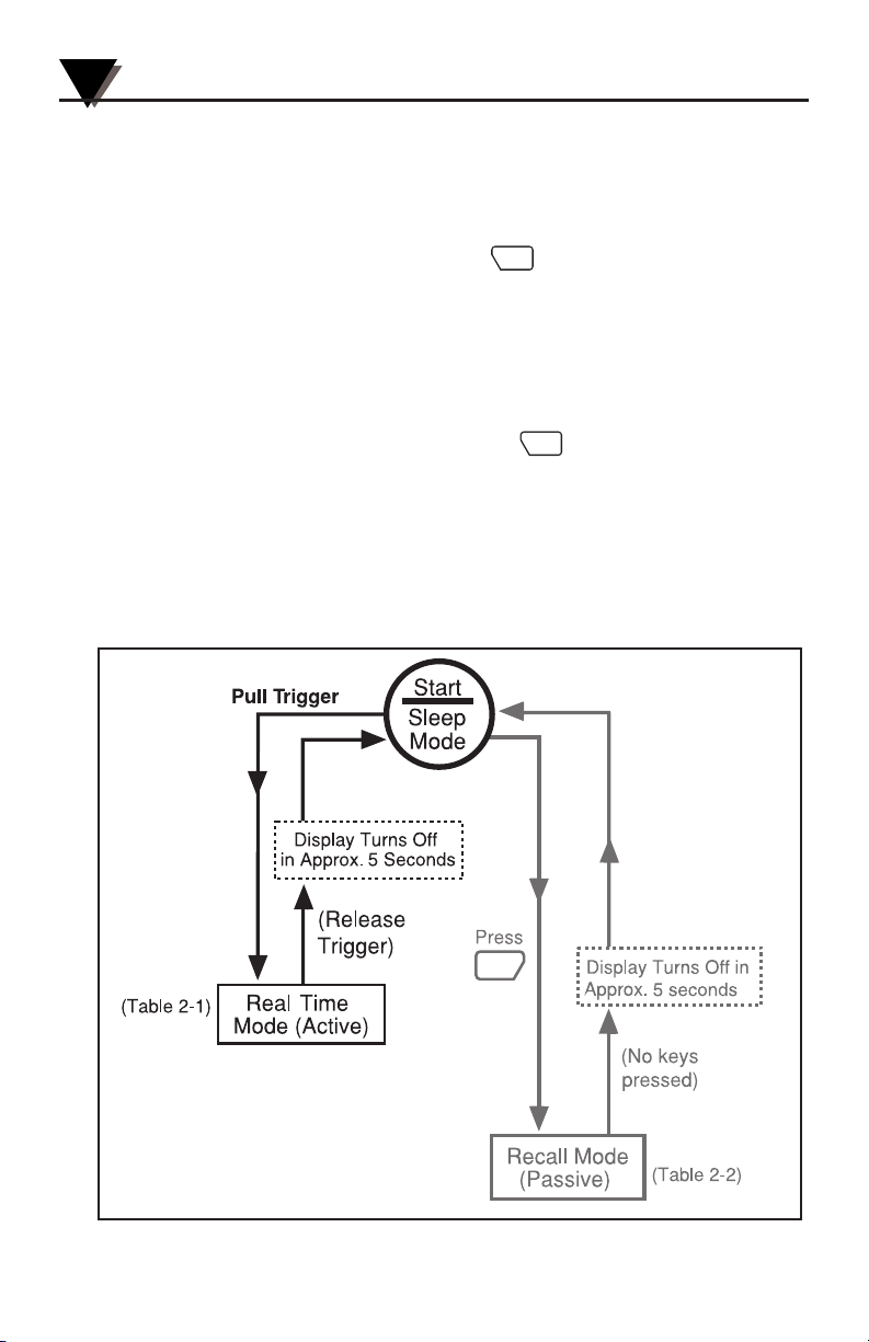
5. After completing a temperature measurement, release the trigger.
In order to conserve battery life, the thermometer goes into sleep
mode and the Laser Sighting turns off.
LOCK
LOCK
F
C
2.2.1 Measurement Techniques
You can use the IR Thermometer to collect temperature data in any
one of five different ways:
• Spot Measurement — Measures the temperature of discrete objects
such as motor bearings, engine exhaust manifolds, etc.:
1. Aim at the desired target and pull the trigger.
2. If necessary, adjust the emissivity using the and
keys.
3. Read the temperature.
• Differential Measurement — Measures the temperature differential
between two spots (the maximum and minimum temperatures
viewed)
1. Aim the thermometer at the first spot and pull the trigger. Press
the key to lock the trigger.
2. If necessary, adjust the emissivity.
3. Aim at the second spot.
4. Adjust the emissivity of the second spot if required.
5. To display the differential temperature, press the key until
“dIF” appears on the display.
6. Read the differential temperature from the upper display.
7. Press the key to unlock the trigger.
LOCK
FUNC
LOCK
F
C
2-7
Using the Handheld Infrared Thermometer
2
• Static Surface Scan – Measures the temperature across a static
surface:
1. Aim the thermometer at a starting point and pull the trigger.
Press the key to lock the trigger.
2. If necessary, adjust the emissivity.
3. Slowly move the thermometer so that the line of sight sweeps
across the surface. The thermometer measures the temperature
at each point on the surface.
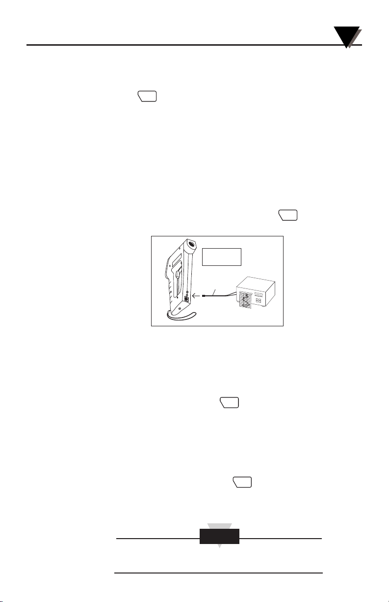
4. To record the temperature profile across the surface, connect
the IR thermometer to a strip chart recorder. Refer to Figure
2-11 for details. The IR thermometer provides an analog output
of 1mV/degree. (0.5 mV/Deg on OS524E)
5. After all the data has been taken, press the key to unlock
the trigger.
Figure 2-11 Recorder Hookup
• Moving Surface Scan - Measures the Temperature of Points on a
Moving Surface:
1. Mount the thermometer on a camera tripod and aim at a fixed
point on the moving surface.
2. Pull the trigger and press the key to lock the trigger.
3. If necessary, adjust the emissivity. The thermometer is now set
up for measuring the temperature of a moving surface.
4. To record the temperature profile of the moving surface,
connect the IR thermometer to a strip chart recorder. Refer to
Figure 2-11 for details.
5. After all data is taken, press the key to unlock the trigger.
• Fixed Point Monitoring Over Time - Monitors the temperature at
a fixed point over time:
It is recommended that you use the ac adapter for long
term measurement of temperature.
LOCK
LOCK
LOCK
LOCK
NOTE
NOTE
Center hole is the
analog output jack
Analog
Cable
To Strip Chart
Recorder
Using the Handheld Infrared Thermometer
2
2-8
1. Mount the thermometer on a camera tripod and aim at the
target.
2. Connect the analog output of the thermometer to a strip chart
recorder as shown in Figure 2-11.
3. Pull the trigger and press the key to lock the trigger.
4. If necessary, adjust the emissivity.
5. The thermometer is now set up for unattended monitoring of
temperature over time. You can also download the temperature
to a Serial Printer or a PC for further analysis (Models OS533E,
OS534E, OS523E, OS524E).
6. After all data is taken, press the key to unlock the trigger.
2.3 Real Time Mode (Active Operation)
Definition: Real Time Mode is the active operational mode of the
thermometer. In this mode, the thermometer constantly measures
and displays temperature.
Figure 2-12. General Operational Block Diagram
LOCK
LOCK
FUNC
2-9
Using the Handheld Infrared Thermometer
2
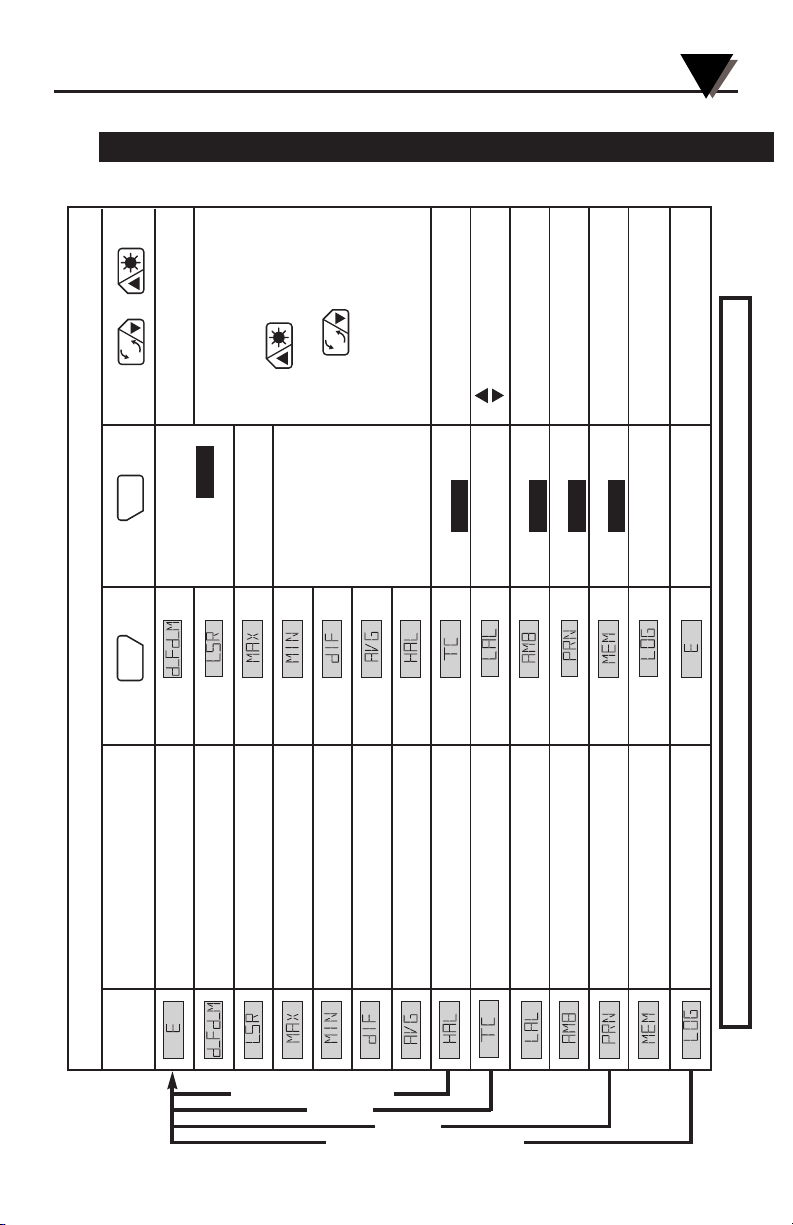
Table 2-1. Functional Flow Chart when the Trigger is Pulled (Real Time Mode)
Press to... to...
Press or to...
FUNC
LOCK
F
C
F
C
DISPLAY
MODE:
Press
Display shows:
Emissivity
Go to
Set Emissivity
Current temperature Lock or unlock
Distance (feet or meter)
Go to
Trigger LCK
Current temperature
Laser status
Go to
Set laser to
Current temperature Flashing or On
Maximum temperature
Go to
Press to turn on/off
Current temperature LCD backlight
Minimum temperature
Go to
Current temperature Reset Maximum, Press to change
Differential temp
Go to
Minimum, Diff.
from °F to °C or feet to meter
Current temperature
Average temps and vise versa
Average temperature
Go to
Current temperature
High alarm set point
Go to
Enable/Disable
Set High Alarm set point
Current temperature HAL
Thermocouple temp
Go to
–––––– Turn on LCD Back lite
Current temperature Change °F to °C
Low alarm set point
Go to
Enable/Disable
Set Low Alarm set point
Current temperature LAL
Ambient target temp
Go to
Enable/Disable
Set Ambient Target temp
Current temperature ATC
Data Trans. Interval
Go to
Enable/Disable
Set Data Transmission
Current Temperature PRN interval (Logging)
Memory location
Go to Store temp data –––
Current temperature
Logging
Go to
Turn on/off
–––
Current temperature Logging
Real Time Modes
NOTE: The unit of measure (°F or °C) flashes during Real Time Mode.
OS530LE, OS530HRE
OS532E
OS533E
OS534E, OS523E, OS524E

Figure 2-13. Visual Function Flow Chart
* While in these 7 modes:
Use key to change temperature from °F to °C or vice versa.
Use key to turn on the display backlighting.
*
*
*
*
*
*
*
Using the Handheld Infrared Thermometer
2
2-10
MODE MODEDISPLAY DISPLAY
LCK
LCK
FUNC
☞
LCK
LCK
HAL
FUNC
☞
LCK
(Models OS530LE,
OS530HRE)
FUNC
☞
LCK
☞
LCK
☞
LCK
FUNC
FUNC
FUNC
☞
LCK
LCK
☞
LCK
ATC
☞
LCK
☞
LAL
☞
FUNC
(Model OS532E)
FUNC
FUNC
PRN
FUNC
(Model OS533E)
☞
FUNC
LCK
LCK
FUNC
☞
FUNC
☞
(Models
on
LCK
FUNC
☞
OS534E,
OS523E,
OS524E)
F
C
2-11
Using the Handheld Infrared Thermometer
2
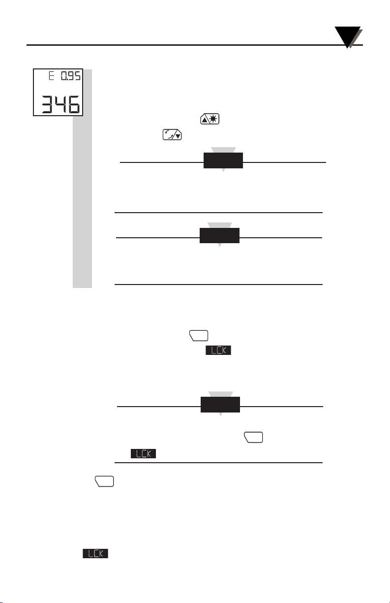
2.3.1 Adjusting Emissivity
Refer to Appendices B and C for information on emissivity.
1. Determine the emissivity of the target.
2. Aim at the target and pull the trigger.
3. If necessary, press the key to increment the target emissivity
or press the key to decrement the target emissivity.
The Emissivity Display Mode (E) appears every time the
trigger is pulled regardless of how the Display Mode was
previously set.
The emissivity setting does not change when the
thermometer is turned off. However, when the batteries are
replaced, the emissivity is reset to 0.95, the default value.
2.3.2 Using the LOCK Function
This function electronically locks the trigger mechanism:
1. Pull the trigger and press the key to lock the trigger in the Emissivity
and Distance Display Mode. The icon will appear on the display.
2. Release the trigger. This allows the thermometer to operate
continuously whether or not the trigger is pulled.
To unlock the trigger function, while in Emissivity and
Distance Display Modes press the key again, and
the icon is no longer displayed.
The key also enables/disables alarm functions, and resets
calculated temperature values (MAX, MIN, dIF, AVG).
2.3.3 Using the Trigger Function
Besides turning on the thermometer by pulling the trigger, you can
lock the trigger electronically by pressing the trigger button twice.
The
icon is displayed. You can unlock the trigger by pressing the
trigger button twice again.
NOTE
NOTE
NOTE
°F
F
C
LOCK
LOCK
LOCK
 Loading...