


 Loading...

Table of Contents |
|
Preface |
|
About this User's Guide ....................................................................................................................... |
5 |
What you will learn from this user's guide ......................................................................................................... |
5 |
Conventions used in this user's guide ................................................................................................................. |
5 |
Where to find more information ......................................................................................................................... |
5 |
Chapter 1 |
|
Introducing the OMB-DAQ-2416-4AO ................................................................................................. |
6 |
Overview: OMB-DAQ-2416-4AO features ....................................................................................................... |
6 |
Software features ................................................................................................................................................ |
6 |
Chapter 2 |
|
Installing the OMB-DAQ-2416-4AO ..................................................................................................... |
7 |
What comes with your OMB-DAQ-2416-4AO shipment? ................................................................................ |
7 |
Hardware .......................................................................................................................................................................... |
7 |
Optional components ........................................................................................................................................................ |
8 |
Additional documentation................................................................................................................................................. |
8 |
Unpacking the OMB-DAQ-2416-4AO .............................................................................................................. |
8 |
Installing the software ........................................................................................................................................ |
8 |
Installing the hardware ....................................................................................................................................... |
8 |
Connecting to an OMB-AI-EXP32 with the DSUB37 expansion connector ..................................................... |
9 |
Configuring the hardware ................................................................................................................................... |
9 |
Connecting the board for I/O operations .......................................................................................................... |
10 |
Connectors, cables – main I/O connector......................................................................................................................... |
10 |
Screw terminal pin out – differential ............................................................................................................................... |
11 |
Screw terminal pin out – single-ended............................................................................................................................. |
12 |
Chapter 3 |
|
Functional Details ............................................................................................................................... |
13 |
OMB-DAQ-2416-4AO components................................................................................................................. |
13 |
LEDs................................................................................................................................................................................ |
14 |
USB connector................................................................................................................................................................. |
14 |
External power connector ................................................................................................................................................ |
14 |
Screw terminal wiring...................................................................................................................................................... |
14 |
Mechanical drawings ........................................................................................................................................ |
15 |
Block diagram .................................................................................................................................................. |
16 |
Analog/TC input terminals ............................................................................................................................... |
17 |
Analog input mode........................................................................................................................................................... |
17 |
Thermocouple inputs ....................................................................................................................................................... |
17 |
Noise filtering, data rate, and throughput rate.................................................................................................................. |
18 |
Multiple-channel throughput rates ................................................................................................................................... |
19 |
Input isolation ................................................................................................................................................... |
20 |
Analog output terminals (VDAC0 through VDAC3) ....................................................................................... |
21 |
Digital I/O......................................................................................................................................................... |
21 |
Internal pull-up/pull-down capability .............................................................................................................................. |
21 |
External pull-up/pull-down capability ............................................................................................................................. |
22 |
Counter input terminals (CTR0, CTR1) ........................................................................................................... |
23 |
3

OMB-DAQ-2416-4AO User's Guide
Chapter 4 |
|
Calibrating the OMB-DAQ-2416-4AO ................................................................................................ |
24 |
Calibration methods.......................................................................................................................................... |
24 |
Factory calibration ........................................................................................................................................................... |
24 |
Self calibration................................................................................................................................................................. |
24 |
Chapter 5 |
|
Specifications...................................................................................................................................... |
25 |
Analog input ..................................................................................................................................................... |
25 |
Channel configurations..................................................................................................................................... |
26 |
Compatible sensors .......................................................................................................................................................... |
26 |
Accuracy........................................................................................................................................................... |
26 |
Thermocouple measurement accuracy ............................................................................................................................. |
26 |
Analog input DC voltage measurement accuracy ............................................................................................................ |
35 |
Input bandwidth ............................................................................................................................................................... |
37 |
Noise performance ........................................................................................................................................................... |
37 |
Channel switching error ................................................................................................................................................... |
38 |
Throughput rate ................................................................................................................................................ |
39 |
Analog voltage output ...................................................................................................................................... |
40 |
Analog input/output calibration ........................................................................................................................ |
41 |
Digital input/output........................................................................................................................................... |
41 |
Counter ............................................................................................................................................................. |
42 |
Memory ............................................................................................................................................................ |
42 |
Microcontroller................................................................................................................................................. |
42 |
Power................................................................................................................................................................ |
43 |
USB specifications ........................................................................................................................................... |
43 |
Environmental .................................................................................................................................................. |
43 |
Mechanical ....................................................................................................................................................... |
43 |
Screw terminal connector type and pin-out ...................................................................................................... |
44 |
Screw terminal pin out ..................................................................................................................................................... |
44 |
Optional OMB-AI-EXP32 expansion module.................................................................................................. |
47 |
OMB-AI-EXP32 screw terminal pin out ......................................................................................................................... |
49 |
OMB-DAQ-2416-4AO screw terminal pin out (with OMB-AI-EXP32 attached)........................................................... |
51 |
4
Preface
About this User's Guide
What you will learn from this user's guide
This user's guide explains how to install, configure, and use the OMB-DAQ-2416-4AO so that you get the most out of its analog I/O, thermocouple (TC) input, digital I/O, and counter/timer I/O features.
This user's guide also refers you to related documents available on our web site, and to technical support resources.
Conventions used in this user's guide
For more information on …
Text presented in a box signifies additional information and helpful hints related to the subject matter you are reading.
Caution! Shaded caution statements present information to help you avoid injuring yourself and others, damaging your hardware, or losing your data.
< : > |
Angle brackets that enclose numbers separated by a colon signify a range of numbers, such as those assigned |
|
to registers, bit settings, etc. |
bold text |
Bold text is used for the names of objects on the screen, such as buttons, text boxes, and check boxes. For |
|
example: |
|
1. Insert the disk or CD and click the OK button. |
italic text |
Italic text is used for the names of manuals and help topic titles, and to emphasize a word or phrase. For |
|
example: |
|
The InstaCal installation procedure is explained in the OMB-DAQ-2416 Series Software User’s Guide. |
|
Never touch the exposed pins or circuit connections on the board. |
Where to find more information
For additional information relevant to the operation of your hardware, refer to the Documents subdirectory where you installed the software, or search for your device on our website at www.omega.com.
5

Chapter 1
Introducing the OMB-DAQ-2416-4AO
Overview: OMB-DAQ-2416-4AO features
The OMB-DAQ-2416-4AO is supported under popular Microsoft® Windows® operating systems. The OMB- DAQ-2416-4AO is a multifunction measurement and control board designed for the USB bus.
The OMB-DAQ-2416-4AO is a full-speed, multiplexed 24-bit measurement system that provides up to 16 differential and up to 32 single-ended (SE) analog inputs. It offers software-selectable analog input ranges of ±20 V, ±10 V, ±5 V, ±2.5 V, ±1.25 V, ±0.625 V, ±0.312 V, ±0.156 V, and ±0.078 V.
It also protects your computer by providing a minimum of 500 VDC input isolation between field wiring and the USB interface.
You can configure up to 16 of the analog inputs as differential thermocouple (TC) inputs. In thermocouple mode, the OMB-DAQ-2416-4AO includes built-in cold-junction compensation and open thermocouple detection.
You can add up to 32 single-ended or up to 16 differential channels by connecting the OMB-DAQ-2416-4AO to an OMB-AI-EXP32 expansion module. Each channel is software-configurable as single-ended or differential. For each channel pair configured differentially, you lose one SE channel.
The OMB-DAQ-2416-4AO has four 16-bit analog output channels with an update rate of up to1102 S/s and an output range of ±10 V.
The device has eight high-speed lines of digital I/O and two 32-bit counters. You can expand up to 24 DIO channels by connecting the OMB-DAQ-2416-4AO to an OMB-AI-EXP32 expansion module.
Six banks of removable screw-terminal blocks provide connectivity to the analog input channels, digital I/O lines, counter/timer channels, and analog outputs.
Software features
For information on the features of InstaCal and the other software included with your OMB-DAQ-2416-4AO, refer to the OMB-DAQ-2416 Series Software User’s Guide that shipped with your device.
6
Chapter 2
Installing the OMB-DAQ-2416-4AO
What comes with your OMB-DAQ-2416-4AO shipment?
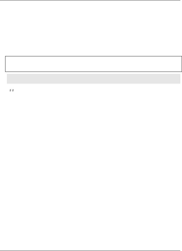
As you unpack your OMB-DAQ-2416-4AO, verify that the following components are included.
Hardware
OMB-DAQ-2416-4AO
USB cable (2-meter length)
OMB-DAQ-2416-ADAP (+5VDC, 10 Watt regulated power supply)
7
OMB-DAQ-2416-4AO User's Guide |
Installing the OMB-DAQ-2416-4AO |
|
|
Optional components
Expansion devices that are compatible with the OMB-DAQ-2416-4AO must be ordered separately. If you ordered any of the following products with your device, they should be included with your shipment:
OMB-AI-EXP32
Analog input expansion module adds up to 16 differential or 32 single-ended inputs to the OMB-DAQ-2416- 4AO.
Additional documentation
In addition to this hardware user's guide, you should also receive the OMB-DAQ-2416 Series Software User’s Guide. This booklet supplies a brief description of the software you received with your OMB-DAQ-2416-4AO and information regarding installation of that software. Please read this booklet completely before installing any software or hardware.
Unpacking the OMB-DAQ-2416-4AO
As with any electronic device, you should take care while handling to avoid damage from static
electricity. Before removing the OMB-DAQ-2416-4AO from its packaging, ground yourself using a wrist strap or by simply touching the computer chassis or other grounded object to eliminate any stored static charge.
If any components are missing or damaged, notify Omega Engineering immediately by phone, fax, or e-mail.
Phone: (203) 359-1660
Fax: (203) 359-7700
Email: das@omega.com
Installing the software
Refer to the OMB-DAQ-2416 Series Software User’s Guide for instructions on installing the software on the
OMB-DAQ-2416 Series Data Acquisition Software CD. This booklet is available in PDF at www.omega.com/manuals.
We recommend that you download the latest Windows Update onto your computer before installing and operating the OMB-DAQ-2416-4AO.
Installing the hardware
To connect the OMB-DAQ-2416-4AO to your system, turn your computer on, and then do the following:
1.Connect the OMB-DAQ-2416-ADAP power supply to the device's external power connector, and plug the other end into a power outlet.
2.Connect the USB cable to the device's USB connector and to a USB port on your computer. A USB2.0 port is recommended.
8

OMB-DAQ-2416-4AO User's Guide |
Installing the OMB-DAQ-2416-4AO |
|
|
When you connect the OMB-DAQ-2416-4AO for the first time, a Found New Hardware message opens as the OMB-DAQ-2416-4AO is detected. When the message closes, the installation is complete.
The power LED (bottom LED) blinks during device detection and initialization, and then remains solid if properly detected. If not, check if the OMB-DAQ-2416-4AO has sufficient power. When the device is first powered on, there is usually a momentary delay before the power LED begins to blink, or come on solid.
Caution! Do not disconnect any device from the USB bus while the computer is communicating with the OMB-DAQ-2416-4AO, or you may lose data and/or your ability to communicate with the OMB- DAQ-2416-4AO.
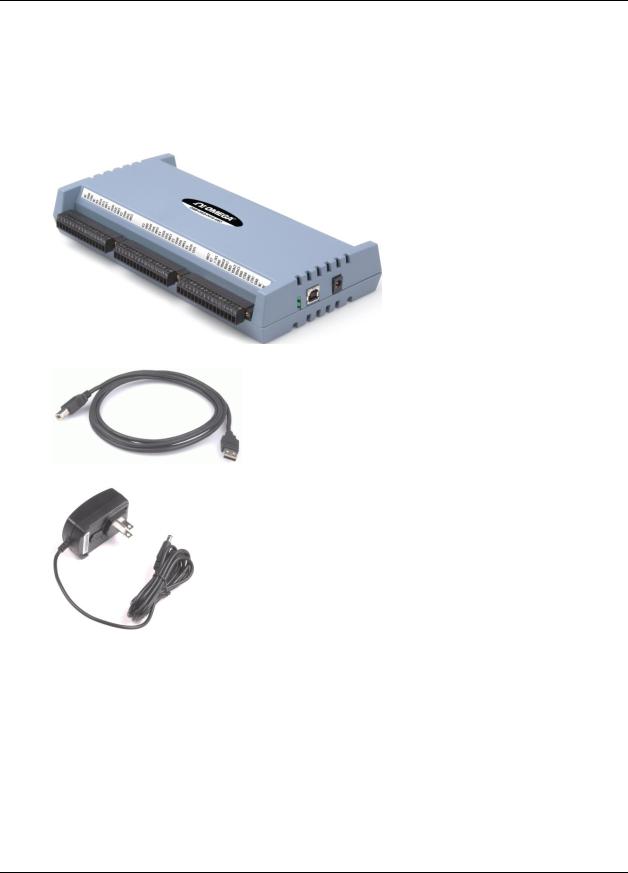
Connecting to an OMB-AI-EXP32 with the DSUB37 expansion connector
Use the 37-pin expansion connector to connect the OMB-DAQ-2416-4AO to an OMB-AI-EXP32 expansion module.
To connect the two devices directly to each other, follow these steps.
1.Disconnect the USB cable from the OMB-DAQ-2416-4AO.
2.Remove the external power cable from the OMB-DAQ-2416-4AO.
3.Connect the two devices together by inserting the OMB-AI-EXP32's DSUB37 connector into the DSUB37 connector on the OMB-DAQ-2416-4AO.
Figure 1. OMB-DAQ-2416-4AO directly connected to an OMB-AI-EXP32
4.Turn the connected modules over and secure the connection by screwing the connection plate to both modules, as shown below.
Figure 2. OMB-DAQ-2416-4AO secured to an OMB-AI-EXP32
5.Connect the external power supply to the OMB-DAQ-2416-4AO's external power connector, and plug the other end into an AC outlet.
6.Connect the USB cable from the OMB-DAQ-2416-4AO to the host computer's USB port.
Connect to a USB 2.0 high speed hub to achieve the highest transfer rate (480 Mbps). When connected to a USB 1.1 full-speed port, the transfer rate is limited to 12 Mbps.
Configuring the hardware
Except for the DIO pull-up selection, all hardware configuration options on the OMB-DAQ-2416-4AO are software controlled. You can select some of the configuration options using InstaCal, such as the analog input configuration (single-ended or differential channels). When measuring from thermocouples, make sure you configure the channels for differential mode.
9

OMB-DAQ-2416-4AO User's Guide |
Installing the OMB-DAQ-2416-4AO |
|
|
Caution! Turn off power to all devices connected to the system before making connections. Electrical shock or damage to equipment can result even under low-voltage conditions.
Caution! Always handle components carefully, and never touch connector terminals or circuit components unless you are following ESD guidelines in an appropriate ESD-controlled area. These guidelines include using properly-grounded mats and wrist straps, ESD bags and cartons, and related procedures.
Avoid touching board surfaces and onboard components. Only handle boards by their edges. Make sure the OMB-DAQ-2416-4AO does not come into contact with foreign elements such as oils, water, and industrial particulate.
The discharge of static electricity can damage some electronic components. Semiconductor devices are especially susceptible to ESD damage.
Connecting the board for I/O operations
Connectors, cables – main I/O connector
The following table lists the board connectors and compatible accessory products for the OMB-DAQ-2416- 4AO.
Main connector specifications
Main connectors |
Six banks of detachable screw terminals |
Compatible accessory product for the 37-pin expansion |
OMB-AI-EXP32 expansion board with screw terminals |
connector |
(connects directly to the OMB-DAQ-2416-4AO) |
|
|
10
OMB-DAQ-2416-4AO User's Guide |
Installing the OMB-DAQ-2416-4AO |
|
|
Screw terminal pin out – differential
No connection |
NC |
1 |
49 |
NC |
No connection |
Channel 0 HI |
CH0H |
2 |
50 |
CH15L |
Channel 15 LO |
Channel 0 LO |
CH0L |
3 |
51 |
CH15H |
Channel 15 HI |
No connection |
NC |
4 |
52 |
NC |
No connection |
No connection |
NC |
5 |
53 |
NC |
No connection |
Channel 1 HI |
CH1H |
6 |
54 |
CH14L |
Channel 14 LO |
Channel 1 LO |
CH1L |
7 |
55 |
CH14H |
Channel 14 HI |
No connection |
NC |
8 |
56 |
NC |
No connection |
No connection |
NC |
9 |
57 |
NC |
No connection |
Channel 2 HI |
CH2H |
10 |
58 |
CH13L |
Channel 13 LO |
Channel 2 LO |
CH2L |
11 |
69 |
CH13H |
Channel 13 HI |
No connection |
NC |
12 |
60 |
NC |
No connection |
No connection |
NC |
13 |
61 |
NC |
No connection |
Channel 3 HI |
CH3H |
14 |
62 |
CH12L |
Channel 12 LO |
Channel 3 LO |
CH3L |
15 |
63 |
CH12H |
Channel 12 HI |
No connection |
NC |
16 |
64 |
NC |
No connection |
No connection |
NC |
17 |
65 |
NC |
No connection |
Analog ground |
GND |
18 |
66 |
GND |
Analog ground |
Channel 4 HI |
CH4H |
19 |
67 |
CH11L |
Channel 11 LO |
Channel 4 LO |
CH4L |
20 |
68 |
CH11H |
Channel 11 HI |
No connection |
NC |
21 |
69 |
NC |
No connection |
No connection |
NC |
22 |
70 |
NC |
No connection |
Channel 5 HI |
CH5H |
23 |
71 |
CH10L |
Channel 10 LO |
Channel 5 LO |
CH5L |
24 |
72 |
CH10H |
Channel 10 HI |
No connection |
NC |
25 |
73 |
NC |
No connection |
No connection |
NC |
26 |
74 |
NC |
No connection |
Channel 6 HI |
CH6H |
27 |
75 |
CH9L |
Channel 9 LO |
Channel 6 LO |
CH6L |
28 |
76 |
CH9H |
Channel 9 HI |
No connection |
NC |
29 |
77 |
NC |
No connection |
No connection |
NC |
30 |
78 |
NC |
No connection |
Channel 7 HI |
CH7H |
31 |
79 |
CH8L |
Channel 8 LO |
Channel 7 LO |
CH7L |
32 |
80 |
CH8H |
Channel 8 HI |
No connection |
NC |
33 |
81 |
GND |
Analog ground |
No connection |
NC |
34 |
82 |
NC |
No connection |
+5 V output |
+5V |
35 |
83 |
NC |
No connection |
Analog ground |
GND |
36 |
84 |
GND |
Analog ground |
Analog out 0 |
VDAC0 |
37 |
85 |
DIO7 |
Digital input/output |
Analog out 1 |
VDAC1 |
38 |
86 |
DIO6 |
Digital input/output |
Analog ground |
GND |
39 |
87 |
DIO5 |
Digital input/output |
Analog out 2 |
VDAC2 |
40 |
88 |
DIO4 |
Digital input/output |
Analog out 3 |
VDAC3 |
41 |
89 |
DIO3 |
Digital input/output |
Analog ground |
GND |
42 |
90 |
DIO2 |
Digital input/output |
Counter input 0 |
CTR0 |
43 |
91 |
DIO1 |
Digital input/output |
Analog ground |
GND |
44 |
92 |
DIO0 |
Digital input/output |
Counter input 1 |
CTR1 |
45 |
93 |
DGND |
Digital I/O ground |
Analog ground |
GND |
46 |
94 |
DGND |
Digital I/O ground |
No connection |
NC |
47 |
95 |
NC |
No connection |
No connection |
NC |
48 |
96 |
NC |
No connection |
Figure 3. 16-channel differential mode pin out
Differential connection guidelines
When connecting differential voltage inputs to a "floating" voltage source, make sure there is a DC return path from each voltage input to ground. You make this path by connecting a resistor from each input to a GND pin (pins 18, 36, 39, 42, 44, 46, 66, 81, 84). A value of approximately 100 kΩ can be used for most applications.
Leave any unused input channels either floating or tied to GND (pins 18, 36, 39, 42, 44, 46, 66, 81, 84). Source impedances should be kept as small as possible to avoid settling time and accuracy errors.
When configuring thermocouple sensors, keep any stray capacitance as small as possible relative to GND (pins 18, 36, 39, 42, 44, 46, 66, 81, 84) to avoid settling time and accuracy errors. For thermocouple channels, do not provide a return path to ground. This is done internally.
11
OMB-DAQ-2416-4AO User's Guide |
Installing the OMB-DAQ-2416-4AO |
|
|
Screw terminal pin out – single-ended
No connection |
NC |
1 |
49 |
NC |
No connection |
Channel 0 |
CH0H |
2 |
50 |
CH15L |
Channel 31 |
Channel 16 |
CH0L |
3 |
51 |
CH15H |
Channel 15 |
No connection |
NC |
4 |
52 |
NC |
No connection |
No connection |
NC |
5 |
53 |
NC |
No connection |
Channel 1 |
CH1H |
6 |
54 |
CH14L |
Channel 30 |
Channel 17 |
CH1L |
7 |
55 |
CH14H |
Channel 14 |
No connection |
NC |
8 |
56 |
NC |
No connection |
No connection |
NC |
9 |
57 |
NC |
No connection |
Channel 2 |
CH2H |
10 |
58 |
CH13L |
Channel 29 |
Channel 18 |
CH2L |
11 |
69 |
CH13H |
Channel 13 |
No connection |
NC |
12 |
60 |
NC |
No connection |
No connection |
NC |
13 |
61 |
NC |
No connection |
Channel 3 |
CH3H |
14 |
62 |
CH12L |
Channel 28 |
Channel 19 |
CH3L |
15 |
63 |
CH12H |
Channel 12 |
No connection |
NC |
16 |
64 |
NC |
No connection |
No connection |
NC |
17 |
65 |
NC |
No connection |
Analog ground |
GND |
18 |
66 |
GND |
Analog ground |
Channel 4 |
CH4H |
19 |
67 |
CH11L |
Channel 27 |
Channel 20 |
CH4L |
20 |
68 |
CH11H |
Channel 11 |
No connection |
NC |
21 |
69 |
NC |
No connection |
No connection |
NC |
22 |
70 |
NC |
No connection |
Channel 5 |
CH5H |
23 |
71 |
CH10L |
Channel 26 |
Channel 21 |
CH5L |
24 |
72 |
CH10H |
Channel 10 |
No connection |
NC |
25 |
73 |
NC |
No connection |
No connection |
NC |
26 |
74 |
NC |
No connection |
Channel 6 |
CH6H |
27 |
75 |
CH9L |
Channel 25 |
Channel 22 |
CH6L |
28 |
76 |
CH9H |
Channel 9 |
No connection |
NC |
29 |
77 |
NC |
No connection |
No connection |
NC |
30 |
78 |
NC |
No connection |
Channel 7 |
CH7H |
31 |
79 |
CH8L |
Channel 24 |
Channel 23 |
CH7L |
32 |
80 |
CH8H |
Channel 8 |
No connection |
NC |
33 |
81 |
GND |
Analog ground |
No connection |
NC |
34 |
82 |
NC |
No connection |
+5 V output |
+5V |
35 |
83 |
NC |
No connection |
Analog ground |
GND |
36 |
84 |
GND |
Analog ground |
Analog out 0 |
VDAC0 |
37 |
85 |
DIO7 |
Digital input/output |
Analog out 1 |
VDAC1 |
38 |
86 |
DIO6 |
Digital input/output |
Analog ground |
GND |
39 |
87 |
DIO5 |
Digital input/output |
Analog out 2 |
VDAC2 |
40 |
88 |
DIO4 |
Digital input/output |
Analog out 3 |
VDAC3 |
41 |
89 |
DIO3 |
Digital input/output |
Analog ground |
GND |
42 |
90 |
DIO2 |
Digital input/output |
Counter input 0 |
CTR0 |
43 |
91 |
DIO1 |
Digital input/output |
Analog ground |
GND |
44 |
92 |
DIO0 |
Digital input/output |
Counter input 1 |
CTR1 |
45 |
93 |
DGND |
Digital I/O ground |
Analog ground |
GND |
46 |
94 |
DGND |
Digital I/O ground |
No connection |
NC |
47 |
95 |
NC |
No connection |
No connection |
NC |
48 |
96 |
NC |
No connection |
Figure 4. 32-channel single-ended mode pin out
GND |
IMEN8 IMEN9 IMEN10 A0_IM A1_IM A2_IM NC NC VCC GND NC GND NC |
LOAD1_DIO LOAD2_DIO IMEN7 |
NC NC |
|||||||
..... ..... ..... ..... ..... ..... ..... ..... ..... ..... ..... ..... ..... ..... ..... ..... ..... ..... ..... |
||||||||||
1 |
2 3 |
4 |
5 |
6 7 |
8 9 |
10 11 12 13 14 |
15 16 17 |
18 19 |
||
20 21 |
22 23 |
24 |
25 |
26 |
27 |
28 29 30 31 32 33 34 35 36 37 |
||||
GND...... ISO_V 3.+3...... |
VA +5...... |
V 5.+20...... |
AGND...... |
V 5.20-...... |
ISO_VDD...... |
INT_EXTDIO...... |
EGND...... NC...... SCK...... MOSI...... SDA...... SCL...... A2_CM...... A0_SM...... A1_SM...... A3_CM...... |
|||
Figure 5. DSUB37 expansion connector pin out
The OMB-AI-EXP32 expansion port is intended to interface directly with the OMB-DAQ-2416-4AO. Do not attempt to use any of the expansion port pins for any other purpose.
Power down the OMB-DAQ-2416-4AO before you connect it the OMB-AI-EXP32 expansion board.
12
Chapter 3
Functional Details
This chapter contains detailed information on all of the features available from the board, including:
Device components
Functional block diagram and mechanical drawings
Signal descriptions
Signal diagrams using default or conventional device settings
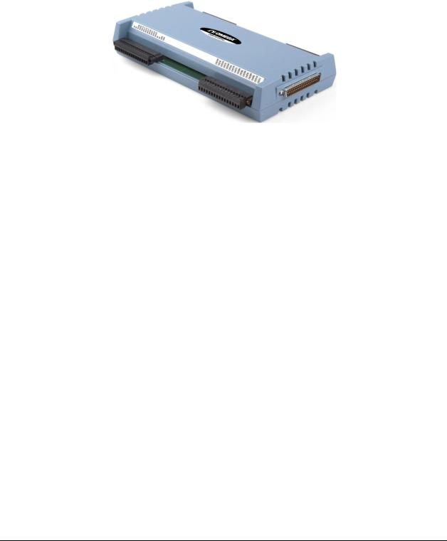
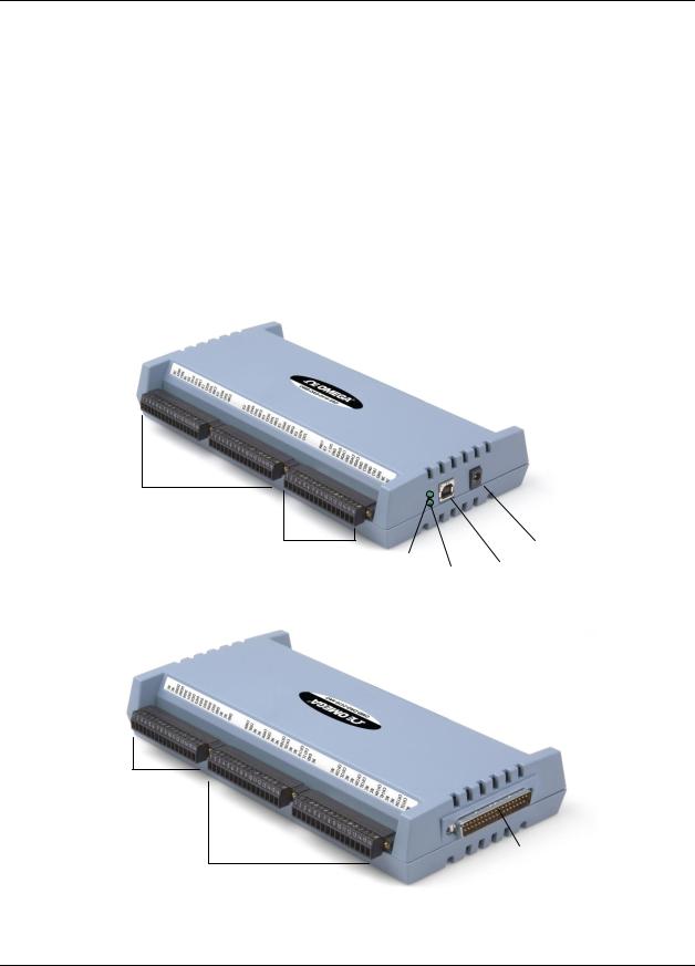
OMB-DAQ-2416-4AO components
These OMB-DAQ-2416-4AO components are shown in Figure 6 and Figure 7.
One USB connector
One external power connector
Two LED indicators ("Power" and "Activity")
One 37-pin DSUB expansion connector
Six removable screw terminal blocks
Analog/TC input screw terminal blocks
·CH 0 – CH 7 differential
·CH 0 – CH 7, CH 16 - CH 23 SE
Analog output and counter screw terminal blocks
Power |
|
External power |
|
connector |
|
LED |
|
|
Activity |
USB |
|
|
connector |
|
|
LED |
|
|
|
Figure 6. Front view components
Digital I/O screw terminal blocks
Analog/TC input screw terminal blocks
·CH 8 - CH 15 differential
·CH 8 - CH 31 single-ended
Figure 7. Rear view components
37-pin expansion connector
13

OMB-DAQ-2416-4AO User's Guide |
Functional Details |
|
|
LEDs
When the OMB-DAQ-2416-4AO is connected to a computer, in its normal idle state both LEDs are lit solid green.
Power LED
The Power LED is the top LED on the right side of the OMB-DAQ-2416-4AO housing.
The Power LED blinks when you plug the power supply into the OMB-DAQ-2416-4AO, and continues to blink while the device initializes the hardware. If it continues blinking for more than ½ second, then there is a problem with the OMB-DAQ-2416-4AO and you should cycle the power.
If an application issues a "blink LED" command, then the power LED blinks a few times.
Activity LED
The (USB) Activity LED is the bottom LED on the right side of the OMB-DAQ-2416-4AO housing. It blinks rapidly when both the USB cable and external power cables are plugged in. It continues blinking rapidly while the device is connecting to the computer, and then turns solid.
Whenever the device receives a USB command, the Activity LED blinks off and then returns to solid green. When an analog in or analog out scan is running, the Activity LED blinks continuously.
USB connector
The USB connector provides communication.
External power connector
Connect the OMB-DAQ-2416-ADAP power supply to this connector. The power supply provides 5 VDC, 10W regulated power.
Screw terminal wiring
The OMB-DAQ-2416-4AO has six groups of screw terminals—three on each side of the housing. Each group has 16 connections. Pin numbers are identified in Figure 3 on page 11 and Figure 4 on page 12.
14
OMB-DAQ-2416-4AO User's Guide |
Functional Details |
|
|
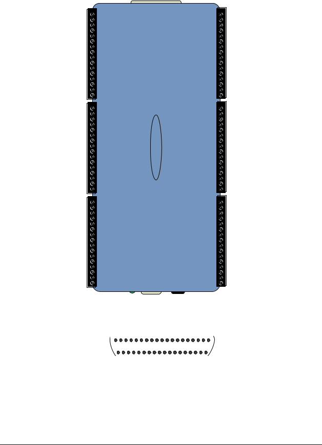
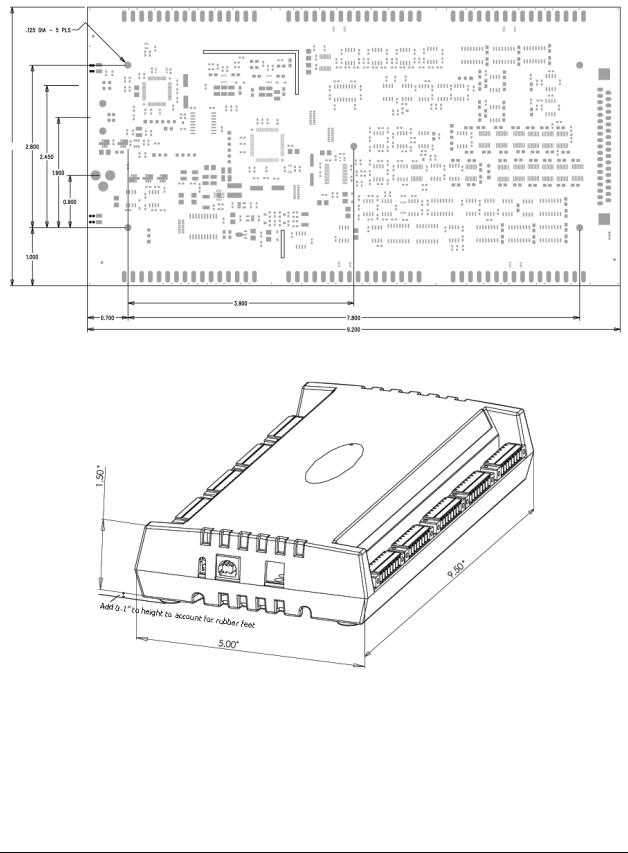
Mechanical drawings
4.800
Figure 8. OMB-DAQ-2416-4AO internal dimensions
Figure 9. OMB-DAQ-2416-4AO case dimensions
15
OMB-DAQ-2416-4AO User's Guide |
Functional Details |
|
|
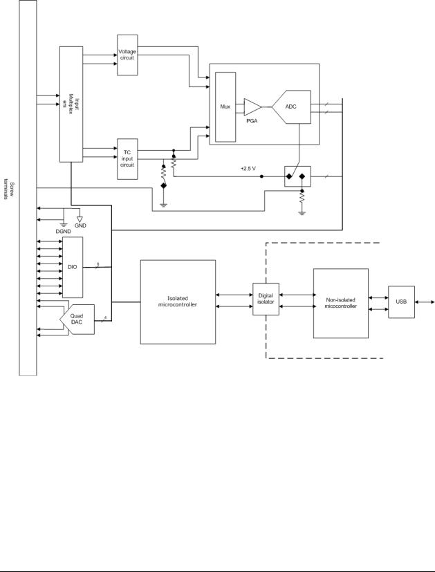
Block diagram
Figure 10 shows a simplified block diagram of the OMB-DAQ-2416-4AO. This device provides all of the functional elements shown in the figure.
Figure 10. OMB-DAQ-2416-4AO functional block diagram
16
Loading...