


Oki RT322CN, RT322TP, RT322TS, RT322TU, RT322CS Manual
...

 Buzzer for RT322/OKIPOS 441
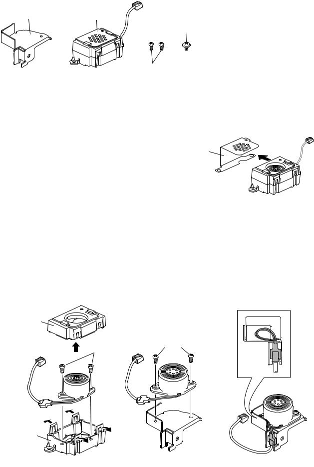
1. Parts : Use the following parts.
Bracket |
Buzzer |
M3 screw
M2.6 screws
( for mounting the bracket )
2. Mounting procedures :
Note : Ensure that power that is supplied to the printer and that all devices connected to the printer have been
2-1.Removing the grounding bracket
Slide the grounding bracket to remove it. (See Fig. 2-1)
Grounding bracket
2-2. Removing the buzzer cover
Remove the four clips on the bottom case to remove the upper case. (See Fig. 2-2) |
< Fig. 2-1 > |
|
Remove the two screws to remove the buzzer from the bottom case. (See Fig. 2-2) |
||
|
||
Note : |
|
2-3. Mounting the bracket
place. (See Fig. 2-3)
2-4. Storing the Cable
Store the connector of the user cable in the bracket as shown in the drawing. (See Fig. 2-4)
Upper case
Not Used |
M2.6 screws |
|
Bottom case |
|
|
< Fig. 2-2 > |
< Fig. 2-3 > |
< Fig. 2-4 > |
58399001 |
|
© Copyright 2009 OKI Data Americas, Inc. |
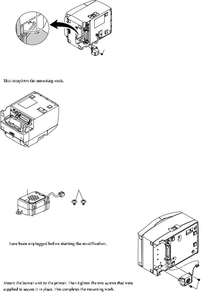
2-5. Installing the Buzzer
Install by hanging the bracket claw on the printer. Tighten the screw.
Note : When attaching the bracket, be careful not to get the buzzer cable caught.
M3 screw
2-6. Connecting the buzzer cable
Plug the buzzer cable into the peripheral drive connector on the back of the printer.
< RT322 >

 For OKIPOS 441
1. Parts : Use the following parts.
Buzzer |
M3 screws |
2. Mounting procedures :
Note : Ensure that power that is supplied to the printer and that all devices connected to the printer have been switched OFF and that the cables
2-1. Connecting the buzzer cable
Plug the buzzer cable into the peripheral drive connector on the back of the printer.
2-2. Mounting the buzzer unit
M3 screws

 Avertisseur sonore pour RT322/OKIPOS 441
1. Composants : Utilisez les composants suivants.
Support |
Avertisseur sonore |
Vis M3
Vis M2 x 6
(pour le montage du support)
2. Procédure d’installation :
Note : Veillez à ce que l’alimentation de l’imprimante et de tout autre dispositif raccordé soit coupée et que les cordons d’alimentation soient débranchés avant de commencer l’installation.
2-1. Retrait du support de mise à la terre
Support de
Coulissez le support de mise à la terre pour le retirer mise à la terre
(voyez la gure 2-1).
2-2. Retrait du couvercle de l’avertisseur sonore |
< Fig. 2-1 > |
Désengagez les quatre agrafes du boîtier inférieur pour retirer le boîtier supérieur (voyez la figure 2-2). Retirez les deux vis pour enlever l’avertisseur sonore du boîtier inférieur (voyez la figure 2-2).
Note : Ces vis ne sont pas utilisées.
2-3. Montage du support
Montez l’avertisseur sonore sur le support. Serrez ensuite les deux vis fournies pour l’immobiliser en place (voyez la gure 2-3).
2-4. Rangement du câble
Rangez le câble et son connecteur dans le support comme montré dans l’illustration (voyez la gure 2-4).
Boîtier supérieur
Non utilisées |
Vis M2 x 6 |
|
Boîtier inférieur
< Fig. 2-2 > |
< Fig. 2-3 > |
< Fig. 2-4 > |
 Loading...