


 Loading...
OKIPAGE 4

 /4
/4
LED Page Printer
Maintenance Manual
OEL/INT
Approval
All specifications are subject to change without notice.
40245101TH
HP, LaserJet and PCL5e are trademarks of Hewlett-Packard Co.
PREFACE
This Maintenance Manual describes the field maintenance methods for LED Page Printers.
This manual is written for use by service persons. Please note that you should refer to the Printer Handbook for the handling and operating methods of the equipment.
|
|
|
CONTENTS |
|
|
1. |
CONFIGURATION ..................................................................................... |
1 - 1 |
|||
|
1.1 |
System Configuration ........................................................................ |
1 - 1 |
||
|
1.2. |
Printer Configuration .......................................................................... |
1 - 2 |
||
|
1.3 |
Option |
................................................................................................. |
1 - 3 |
|
|
1.4 |
Specification ...................................................................................... |
1 - 4 |
||
|
1.5 |
Safety ...............................................................................Standards |
1 - 6 |
||
|
|
1.5.1 .................................................................................... |
Certification Label |
1 |
- 6 |
|
|
1.5.2 ......................................................................................... |
Warning Label |
1 |
- 6 |
2. |
OPERATION ....................................................................DESCRIPTION |
2 - 1 |
|||
|
2.1 |
Main Control ............................................................................Board |
2 - 4 |
||
|
2.2 |
Power .............................................................................Supply Unit |
2 - 5 |
||
|
2.3 |
High-Voltage ....................................................Power Supply Board |
2 - 5 |
||
|
2.4 |
Electro ........................................................-Photographic Processor |
2 - 7 |
||
|
2.5 |
Electro ...........................................................-Photographic Process |
2 - 11 |
||
|
|
2.5.1 .................................................. |
Explanation of Each Process Operation |
2 |
- 13 |
|
2.6 |
Paper .........................................................................Jam Detection |
2 - 19 |
||
|
2.7 |
Toner ..........................................................................Low Detection |
2 - 21 |
||
|
2.8 |
Cover .......................................................................................Open |
2 - 22 |
||
3. |
PARTS REPLACEMENT ........................................................................... |
3 - 1 |
|||
|
3.1 |
Precautions ...................................................for Parts Replacement |
3 - 1 |
||
|
3.2 |
Parts Layout....................................................................................... |
3 - 3 |
||
|
3.3 |
Replacing .................................................................................Parts |
3 - 6 |
||
|
|
3.3.1 ........................................................................................... |
Hopper Plate |
3 |
- 6 |
|
|
3.3.2 .................................................................... |
LED Head and Head Spring |
3 |
- 7 |
|
|
3.3.3 ......................................................................................... |
Transfer Roller |
3 |
- 8 |
|
|
3.3.4 ................................................................................... |
Upper Cover Assy |
3 |
- 9 |
|
|
3.3.5 .......................................................... |
High - Voltage Power Supply Board |
3 |
- 10 |
|
|
3.3.6 ...................................................... |
Top Cover Assy and Flat Cable Assy |
3 |
- 11 |
|
|
3.3.7 ........................................................................................... |
Paper Holder |
3 |
- 12 |
|
|
3.3.8 ..................................................................... |
Side Plate M and Idle Gear |
3 |
- 13 |
|
|
3.3.9 ................................................................................................ |
Heat Assy |
3 |
- 14 |
|
|
3.3.10 ..................................................... |
Drive Shaft E (Eject) and Eject Roller |
3 |
- 17 |
|
|
3.3.11 ......................................................... |
Pressure Roller B (Back Up Roller) |
3 |
- 18 |
|
|
3.3.12 ...................................................................................... |
Separator Guide |
3 |
- 19 |
|
|
3.3.13 .................................................................................. |
Pulse Motor (Main) |
3 |
- 21 |
|
|
3.3.14 ................................................................................. |
Hopping Shaft Assy |
3 |
- 22 |
|
|
3.3.15 ............................................................................................ |
Resist Roller |
3 |
- 23 |
|
|
3.3.16 ................. |
Paper Sensor E, Paper Sensor Exit and Toner Sensor Assy |
3 |
- 24 |
|
|
3.3.17 ............................................................................................... |
Base Plate |
3 |
- 25 |
4. ADJUSTMENT ........................................................................................... |
4 - 1 |
||
4.1 |
Adjustment Types and Functions ...................................................... |
4 - 1 |
|
|
4.1.1 |
Printer Driver ........................................................................................... |
4 - 1 |
|
4.1.2 |
Engine Maintenance Utility ...................................................................... |
4 - 3 |
4.2 |
Adjustment When Replacing a Part ................................................... |
4 - 3 |
|
|
4.2.1 |
Setting LED Head Drive Time ................................................................. |
4 - 3 |
|
4.2.2 |
Setting the LED Head Dot Count ............................................................ |
4 - 4 |
|
4.2.3 |
Uploading and Downloading EEPROM Data .......................................... |
4 - 5 |
5. PERIODICAL MAINTENANCE ................................................................. |
5 - 1 |
|
5.1 |
Periodical Replacement Parts ........................................................... |
5 - 1 |
5.2 |
Cleaning............................................................................................. |
5 - 1 |
|
5.2.1 Cleaning of LED Lens Array .................................................................... |
5 - 1 |
6. TROUBLESHOOTING PROCEDURES .................................................... |
6 - 1 |
|||
6.1 |
Troubleshooting Tips ......................................................................... |
6 - 1 |
||
6.2 |
Check Points Before Correcting Image Problems ............................. |
6 - 1 |
||
6.3 |
Notes When Correcting Image Problems .......................................... |
6 - 1 |
||
6.4 |
Preparation Before Troubleshooting .................................................. |
6 - 1 |
||
6.5 |
Troubleshooting ................................................................................. |
6 - 2 |
||
|
6.5.1 |
Status Monitor Message List ................................................................... |
6 |
- 2 |
|
6.5.2 |
Status Message Troubleshooting ............................................................ |
6 |
- 6 |
|
6.5.3 |
Image Troubleshooting ............................................................................ |
6 |
- 13 |
7. |
WIRING DIAGRAM ................................................................................... |
7 - 1 |
|||
|
7.1 |
Interconnect Signal Diagram ............................................................. |
7 - 1 |
||
|
7.2 |
PCB Layout ........................................................................................ |
7 - 3 |
||
|
|
7.2.1 Main Control Board (HBMC-2 PCB)(OKIPAGE 4w plus) ........................ |
7 - 3 |
||
|
|
7.2.2 Main Control Board (HBMC-3 PCB)(OKIPAGE 4m) ............................... |
7 - 4 |
||
|
|
7.2.3 High-Voltage Power Sapply Board .......................................................... |
7 - 5 |
||
8. |
PARTS LIST |
.............................................................................................. |
8 - 1 |
||
APPENDIX |
A |
LOCAL PRINTING ............................................................... |
A - 1 |
||
APPENDIX |
B |
PARALLEL INTERFACE ..................................................... |
B - 1 |
||
APPENDIX |
C |
MACINTOSH INTERFACE ................................................... |
C - 1 |
||
APPENDIX |
D |
MAINTENANCE UTILITY ..................................................... |
D - 1 |
||

1. CONFIGURATION
1.CONFIGURATION
1.1System Configuration
The OKIPAGE 4w Plus/4m consists of a control block, a power supply unit, and an engine block. (See Figure 1-1.)
ENGINE UNIT
Paper Feed Mechanism |
Hopper |
Plate |
Electro-photographic |
Processor |
High-Voltage Power |
Supply Board |
Main Control Board |
Power Supply Unit |
*2MB Memory |
Expansion Board |
*: Option (OKIPAGE 4m Only)
Figure 1-1
1 - 1

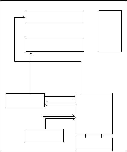
1.2Printer Configuration
The printer unit consists of the following five hardware components:
•Electro-Photographic Processor
•Paper Feeder
•Main Control Board
•High-Voltage Power Supply Board
•Power Supply Unit
Figure 1-2 is the configuration of the printer unit.
Upper Cover Assy
EP Unit
Top Cover Assy
Heat Assy
Power Supply Unit
Main Control Board
High-Voltage Power
Supply Board
1 - 2

1.3Option
(1)2MB HBRB-PCB Option Memory Board(Only OKIpage 4m)
1 - 3
1.4Specification
(1) |
Type |
Desktop |
|
(2) |
Outside dimensions |
Height 5.9” |
(150 mm) |
|
(excludes protruding |
Width 12.2” |
(310 mm) |
|
portion) |
Depth 7.5” |
(191 mm) |
(3) |
Weight |
3.8 kg |
|
(4) |
Development method |
Dry non-magnetic development system |
|
|
Exposure method |
LED stationary head |
|
(5) |
Paper used |
<Type> |
|
•Standard paper
–Xerox 4200 (20 lbs)
•Application paper (manual face-up feed)
–Label
–Envelope
–OHP paper (Transparency)
<Size>
|
|
14" (355.6 mm) (Max.) x 8.5" (215.9 mm) |
|
|
|
<Thickness> |
|
|
|
– Automatic feed: |
16 to 28 lbs (60 to 90 g/m2) |
|
|
– Manual feed: |
Label, Envelope, OHP paper (trans- |
|
|
|
parency) |
(6) |
Printing speed |
First print: |
23 seconds (A4) (after warm-up) |
|
|
Continuous print: |
4 sheets/minute (A4) |
|
|
Warm-up time: |
40 seconds (120 VAC for ODA, 230 |
|
|
|
VAC for OEL/INT) (at room tempera- |
|
|
|
ture 77 ˚F (25 ˚C)) |
(7) |
Paper feeding method |
Automatic paper feed or manual paper feed |
|
(8) |
Paper delivery method |
Face down |
|
(9) |
Resolution |
300 dpi x 300 dpi, 600 dpi x 600 dpi (quasi) |
|
(10) Power input |
230 VAC +15%, -14% (for OEL/INT) |
||
|
|
120 VAC +6%, -15% (for ODA) |
|
(11) Power consumption |
Peak: |
450W |
|
|
|
Typical operation: |
100W |
|
|
Idle: |
30W |
|
|
Power save mode: |
5W |
1 - 4
(12) Temperature and humidity
|
Temperature |
Humidity |
|
|
|
During operation |
10 to 32 ˚C |
20 to 80% RH (relative humidity) |
|
|
|
In storage |
–10 to +43 ˚C |
10 to 90% RH (relative humidity) |
|
|
No condensation is permissible. |
|
|
|
Caution: Temperature and humidity in storage are measured with the OKIPAGE 4w plus/4m being packed; they are valid for one year.
(13) Noise |
During operation: |
48 dB (A) or less |
|
Standby: |
38 dB (A) or less |
(14) Consumables |
Toner cartridge kit |
1,000 (5% duty) |
|
Image drum cartridge |
10,000 (at continuouts printing) |
1 - 5

1.5Safety Standards
1.5.1Certification Label
The safety certification label is affixed to the following location of the OKIPAGE 4w:
OKI-INT
4w Plus
1.5.2Warning Label
Warning labels are affixed to the locations that may cause bodily injury.
During maintenance, do work with enough care while following instructions on these warning labels.
For OEL
For OEL, OKI-INT
For Korea |
For China, TAIWAN |
1 - 6

2.OPERATION DESCRIPTION
2.OPERATION DESCRIPTION
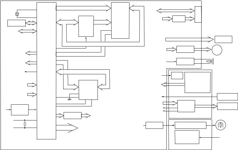
The OKIPAGE 4w Plus/4m consists of a main control board, a high-voltage power supply board, a power supply unit, and an electro-photographic processor. The OKIPAGE 4w Plus/4m receives print data from a higher-level interface and sequentially stores it in memory. The OKIPAGE 4w Plus/4m decodes and edits the received data while storing print data from the interface in memory. It sequentially transfers the edited data to the LED head for each dot line. The electrophotographic processor then prints the data on sheets of paper.
The display of the higher-level host is used for device operation and status display.
Figure 2-1 is the block diagram of the OKIPAGE 4w Plus/4m.
2 - 1
2 - 2
10 MHz
A8 ~ A15
|
MSM65917 |
|
EEPROM |
(nX-8 core) |
AD0 ~ AD7 |
|
||
|
|
Parallel
I/F
LED head
Main motor
Electromagnetic
clutch
Sensors
A0 ~ A10
TEMP TR-VSEN TR-ISEN
5V |
Reset |
|
circuit |
||
|
||
|
Driver |
|
|
5V |
EPROM
(52 KByte)
A0 ~ A7
Address
latch
 OE
OE  CS
CS
D0 ~ D3
D-RAM
(512 KB: For INT)
(128 KB: For OEL)
High-voltage power I/F
OVL
LED
HEAT ON
<Main Control Board>
D0 ~ D7 |
Parallel |
|
I/F |
LED head
Main motor
Electromagnetic
clutch
LED
Sensors
CN
Parallel
I/F
LS07
|
|
LED head |
|
|
Driver |
M |
Main motor |
|
Driver |
Electromagnetic |
|
|
clutch |
|
|
|
|
|
|
LED |
Manual feed sensor |
|
|
|
Paper sensor |
|
|
|
Outlet sensor |
|
|
|
Toner sensor |
|
|
|
Cover open switch |
|
|
TEMP |
|
Thermistor |
|
High-voltage |
High voltage |
|
|
power I/F |
|
||
power |
EP cartridge |
||
TR-VSEN |
|||
supply |
|
||
TR-ISEN |
|
||
|
|
||
|
<High-voltage Power Supply Board> |
|
HEAT ON |
Driver |
+24 V 
+5 V  0VL
0VL  0VP
0VP 
AC output ON/OFF |
Heater |
|
(Halogen lamp) |
||
|
||
Switching |
AC |
|
power supply |
(120 V/230 V) |
<Power Supply Unit>
Figure 2-1 Block Diagram (OKIPAGE 4w Plus)
|
10 MHz |
|
|
EEPROM |
|
|
Parallel |
|
|
I/F |
|
Mac I/F |
||
|
IC Driver |
|
|
LED head |
|
|
Main motor |
|
Electromagnetic |
||
|
clutch |
|
3 - 2 |
Sensors |
|
|
||
|
TEMP |
|
|
TR-VSEN |
|
|
TR-ISEN |
|
5V |
Reset |
|
circuit |
||
|
||
|
5V |
|
|
OVL |
|
|
|
|
|
|
|
|
CN |
|
|
|
A8 ~ A15 |
|
|
D0 ~ D7 |
Parallel |
|
|
|
|
|
|
|
|
EPROM |
I/F |
|
Parallel |
|
|
|
|
|
|
(52 KByte) |
|
|
|
||
MSM65917 |
|
|
|
|
|
I/F |
|
|
|
|
|
|
|
|
|
|
|
||
(nX-8 core) |
|
|
|
|
|
LS07 |
|
|
|
AD0 ~ AD7 |
|
|
A0 ~ A7 |
|
|
|
|
|
|
|
Address |
|
|
|
|
|
|
||
|
|
|
|
|
|
|
|
|
|
|
|
latch |
|
OE |
|
|
|
|
|
|
|
|
|
|
|
|
|
|
|
|
|
|
|
CS |
|
|
|
|
|
|
|
|
|
|
LED head |
|
|
LED head |
|
|
|
|
|
|
Main motor |
|
Driver |
M |
Main motor |
|
|
|
|
(Option RAM-PCB) |
Electromagnetic |
|
Driver |
Electromagnetic |
|
|
|
|
|
|
|
||||
|
|
|
|
|
clutch |
|
clutch |
||
|
|
|
|
|
|
|
|||
|
|
D0 ~ D3 |
|
|
|
|
|
|
|
|
|
|
|
|
LED |
LED |
Manual feed sensor |
|
|
|
|
|
|
|
|
|
Paper sensor |
|
|
|
|
|
|
|
Sensors |
|
Outlet sensor |
|
|
|
A0 ~ A10 |
|
|
D-RAM |
|
Toner sensor |
|
|
|
|
D-RAM |
|
|
|
|
||||
|
|
|
Cover open switch |
|
|
||||
|
|
(2 MByte) |
|
|
|
|
|||
|
|
(512 KByte) |
|
|
|
|
|||
|
|
|
|
|
|
|
|||
|
|
option |
|
|
|
|
|
||
|
|
|
|
TEMP |
|
|
|
Thermistor |
|
|
|
|
|
|
|
|
|
||
|
|
|
|
|
High-voltage |
High voltage |
|
|
|
|
|
|
|
|
power I/F |
|
|
||
|
|
|
|
|
|
power |
|
EP cartridge |
|
|
|
|
|
|
TR-VSEN |
|
|
||
|
|
|
|
|
|
supply |
|
|
|
|
|
|
|
|
TR-ISEN |
|
|
|
|
|
|
|
|
|
|
|
|
|
|
|
Driver |
|
High-voltage power I/F |
|
<High-voltage Power Supply Board> |
|
|
||
|
|
LED |
|
HEAT ON |
Driver |
AC output ON/OFF |
|
Heater |
|
|
|
|
|
(Halogen lamp) |
|||||
|
|
HEAT ON |
|
|
|
|
|
|
|
|
|
|
|
+24 V |
|
|
|
|
|
|
|
|
|
|
|
Switching |
|
|
|
|
|
|
|
|
+5 V |
|
|
AC |
|
|
|
<Main Control Board> |
0VL |
power supply |
|
(120 V/230 V) |
|||
|
|
0VP |
|
|
|
|
|||
<Power Supply Unit>
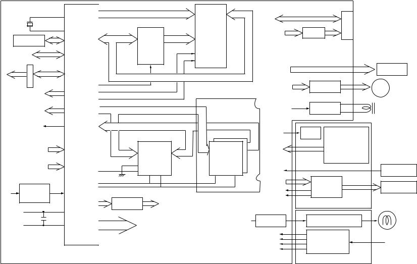
Figure 2-1 Block Diagram (OKIPAGE 4m)
2.1Main Control Board
The main control board consists of a one-chip CPU, a program ROM, a DRAM, an EEPROM, a host interface circuit, and a mechanism driving circuit. The mechanism driving circuit consists of a LED head, a main motor, and an electromagnetic clutch.
(1)One-chip CPU
The one-chip CPU is a custom CPU (8-bit internal bus, 8-bit external bus, 10-MHz clock) incorporating mask ROM and CPU peripheral devices. This CPU has the functions listed in the table below.
Built-in Device |
Function |
|
|
|
|
DRAM controller |
Controls DRAM. |
|
|
|
|
DMA controller |
Transfers image data from Parallel I/F to DRAM, from DRAM to a video output port and |
|
|
between CPU and DRAM. |
|
|
|
|
Parallel interface controller |
Controls the parallel interface. |
|
|
|
|
Video output port |
Controls LED head. |
|
LED STB output port |
|
|
|
|
|
Timer |
Generates various control timings for monitoring paper feeding and a paper size. |
|
|
|
|
I/O port |
Inputs and outputs the sensor signals and motor signals, etc. |
|
Also performs I/O for EEPROM. |
||
|
||
|
|
|
A/D converter |
Inputs the feedback signals from a high-voltage generation circuit and thermistor signal. |
|
|
|
(2)Program ROM
Program ROM contains a program for the equipment. EPROM is used as program ROM. When mask ROM in the one-chip CPU explained in (1) above is valid, the EPROM is not mounted. (For details on short wiring setting, see Section 7.2.)
(3)DRAM
DRAM is used as resident memory.
(4)EEPROM
EEPROM holds the following data:
•Menu data
•Counter value
•Adjustment value
(5)Parallel interface
The parallel interface receives parallel data from the host; it conforms to the IEEE1284 specification.
(6)Macintosh interface <only OKIPAGE 4m>
Mcintosh interfacce receives serial data from the host ; it conforms to the IEEE1284.
2 - 4
2.2Power Supply Unit
The power supply unit supplies +5 V and +24 V to the main control board according to 230 VAC /120 VAC.
Output voltage |
Application |
|
|
+5 V |
Used to generate a logic circuit and a high voltage. |
|
|
+24 V |
Used to drive the motor and electromagnetic clutch. |
|
|
The power supply unit also contains a heater drive circuit.
2.3High-Voltage Power Supply Board
(1)High-Voltage power supply circuit
The high-voltage power supply circuit generates the following voltages required for the electro-photographic processor from +5 V according to the control sequence from the main control board. When the cover is open, +5 V supply is automatically interrupted to stop highvoltage output.
Output |
|
Voltage |
Application |
|
|
|
|
CH |
–1.35 KV |
Voltage to be applied to a charge roller. |
|
|
|
|
|
DB |
–300 V/+300 V |
Voltage to be applied to a developing roller. |
|
|
|
|
|
SB |
–450 V/ 0 V |
Voltage to be applied to a sponge roller. |
|
|
|
|
|
CB |
+400 |
V |
Voltage to be applied to a cleaning roller. |
|
|
|
|
TR |
+500 |
V ~ +3.5 KV/–750 V |
Voltage to be applied to a transfer roller. |
|
|
|
|
Caution: The TR voltage varies with medium and transfer roller impedance.
2 - 5
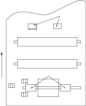
(2)Sensors
The high-voltage power supply board consists of the high-voltage power supply circuit that supplies power to the electro-photographic processor system and the photosensor that detects a paper feeding system and toners.
Figure 2-2 shows the sensor layout drawing.
Exit roller
Paper feeding direction
Outlet sensor
Heat roller
Transfer roller
Feed roller
Paper sensor
Toner |
Hopping |
|
sensor |
||
roller |
||
assy |
||
|
Manual feed sensor |
Figure 2-2
Sensor |
Function |
Sensing State |
|
|
|
Manual feed |
Monitors whether paper was inserted into the manual feed sensor |
ON: Paper exists. |
sensor |
section. |
OFF: No paper exists. |
|
|
|
Paper sensor |
Detects the leading part of the paper. |
ON: Paper exists. |
|
Monitors paper feeding. |
OFF: No paper exists. |
|
|
|
Outlet sensor |
Monitors paper feeding and the paper size according to the paper |
ON: Paper exists. |
|
sensor arrival and passing time. |
OFF: No paper exists. |
|
|
|
Toner sensor |
Detects the low toner status. |
ON (long): Toner low |
|
|
OFF (short): Toner High |
|
|
|
2 - 6
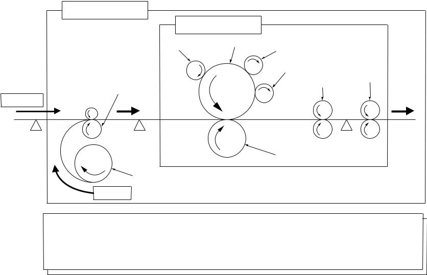
2.4Electro-Photographic Processor
The electro-photographic processor prints out the image data to be sent from the main control board on sheets of paper. Figure 2-3 shows the layout drawing of the electro-photographic processor.
(1)Image drum unit
The image drum unit makes a toner adhere to the formed electrostatic latent image with static electricity. This electrostatic latent image is formed by the lights irradiated from LED heads.
(2)Electromagnetic clutch
The electromagnetic clutch controls the rotation of the hopping roller according to signals from the control block.
2 - 7
Charge roller (ø 9.000)
6.77
LED head
Drum roller (ø 16.000)
17.23
Developing roller (ø 14.000)
23.18
12.72
8 - 2
Paper sensor
Feed roller
10
Manual
printing
OFF
Manual feed sensor
10
ON OFF
Tray printing
Exit roller
Heat roller (ø 19.910)
Cleaning roller
Outlet sensor
(ø 9.000)
6.85
10 OFF
26.50
ON
20.32
64.60
Single tray
|
Transfer roller |
32.00 |
(ø 15.000) |
Hopping roller
Figure 2-3 Layout Drawing of Electro-Photographic Processor
(3)Pulse motor (Main)
This pulse motor of 48 steps/rotation is two-phase excited by the signal from the main control board; it performs feeding control by switching normal rotation to reverse rotation or vice versa and turning on/off the electromagnetic clutch. The relationship between the main motor, electromagnetic clutch, resist gear, drum gear, hopping roller is shown in the table below and on the subsequent pages.
Main Motor |
Electromagnetic Clutch |
|
Hopping Roller |
Regist Gear |
Drum Gear |
Operation |
|
|
|
|
|
|
|
Normal rotation |
OFF |
|
Non-rotation |
Non-rotation |
Rotation |
Warm-up |
|
|
|
|
|
|
|
Reverse rotation |
ON |
|
Rotation |
Rotation |
Rotation |
Hopping |
|
|
|
|
|
|
|
OFF |
|
Non-rotation |
Rotation |
Rotation |
Prinitng |
|
|
|
|||||
|
|
|
|
|
|
|
(4)LED head
The shift and latch registers receive image data from the main control board for each dot line. 2,560 or 2,496 LEDs are driven to radiate the image drum.
(5)Heat Assy
The heat Assy consists of a heater, a heat roller, a thermistor, and a thermostat.
The power supply unit supplies AC voltage to the heater according to the HEATON signal from the main control board to heat the heat roller. The main control board monitors the heat roller temperature via the thermistor and keeps the temperature constant by turning on/off the heater AC voltage supply.
If the heat roller temperature rises abnormally, the thermostat of the heater voltage supply circuit functions to forcibly suspend the AC voltage supply.
2 - 9
10 - 2
2Roller to be driven by reverse rotation of pulse motor (Main)
1Motor to be driven by normal rotation of pulse motor (main)
Developing roller |
Drum roller |
|
CH roller |
||
|
Cleaning roller
Exit roller
Heat roller
Feed roller
Manual printing
Manual |
Paper sensor |
Outlet |
feed |
|
sensor |
sensor |
|
|
|
|
Transfer roller |
Hopping roller
TRAY printing
Roller control by pulse motor (main)
1 Normal rotation of pulse motor (main): Drum roller, transfer roller, cleaning roller, CH roller, developing roller, heat roller, exit roller rotation
2 Reverse rotation of pulse motor (main): Drum roller, transfer roller, cleaning roller, CH roller, developing roller, heat roller, exit roller, feed roller, hopping roller rotation
Hopping operation from the tray, however, is performed when the electromagnetic clutch is turned on.
Figure 2-4 Schematic Drawing of OKIPAGE4w Plus/4m Paper Feeding
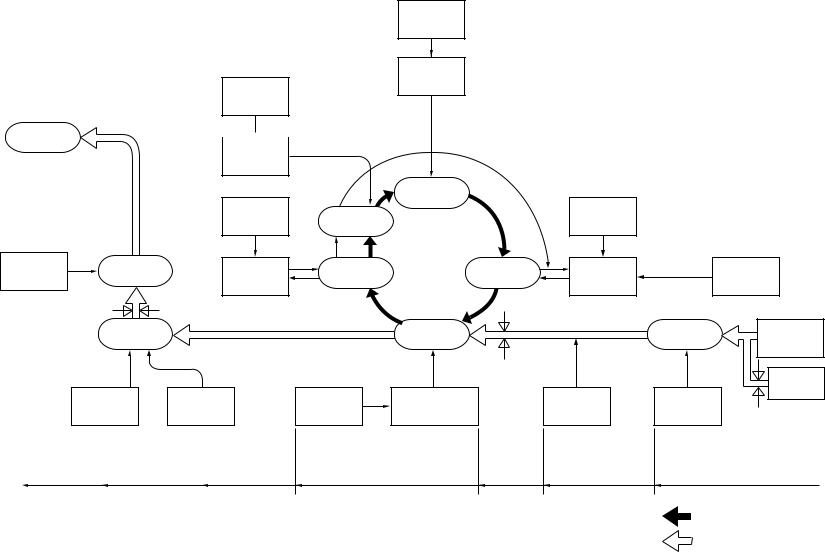
2.5Electro-Photographic Process
(1)Electro-photographic process
The electro-photographic process is outlined below.
1 Charging
The surface of the OPC drum is charged negatively and uniformly by applying the DC voltage to the CH roller.
2Exposure
Light emitted from the LED head irradiates the negatively charged surface of the OPC drum. The surface potential of the irradiated surface attenuates to form the electrostatic latent image corresponding to the image signal.
3Development and residual toner recovery
The negatively charged toner is brought into contact with the OPC drum, adhering to the electrostatic latent image on the OPC drum by static electricity. This adhesion causes the electrostatic latent image to change to a visible image.
At the same time, the residual toner on the OPC drum is attracted to the developing rollerby static electricity.
4Transfer
When paper is placed over the image drum surface, the positive charge which is opposite in polarity to that of the toner, is applied to the reverse side by the transfer roller. The toner is attracted by the positive charge and is transferred onto the paper. This results in the transfer of the toner image formed on the image drum onto the paper.
5Cleaning
The cleaning roller temporarily attracts the residual toner on the transferred OPC drum with static electricity, then returns the toner to the OPC drum.
6Fusing
The transferred unfused toner image is fused to a sheet of paper by applying heat and pressure to the image.
Figure 2-5 is a flow for the electro-photographic process.
2 - 11
12 - 2
Power supply
Paper delivery  Charge
roller
Power supply
Paper eject |
Paper feeding |
Cleaning |
|
roller |
|||
|
roller |
||
|
|
||
Outlet sensor |
|
|
|
|
Fusing |
|
Heat roller
Back-up
roller
Paper ejection |
Fusing |
Cleaning |
|
|
|
Control signal
LED head
|
Exposure |
|
|
|
Charging |
|
|
Power |
|
|
|
supply |
|
|
Cleaning |
|
Development |
Developing |
|
|
|
|
roller |
|
|
Transfer |
|
|
Paper |
|
|
|
supply |
|
|
|
|
|
|
|
|
Paper sensor |
|
|
Power |
Transfer roller |
|
Feed roller |
Hopping |
supply |
|
roller |
||
|
|
|
Toner cartridge
Paper holder
Manual feed section
Manual feed sensor
Transfer |
Development |
Paper feed |
Paper hopping |
:OPC drum rotation direction
:Paper feeding path
Figure 2-5 Flow for Electro-Photographic Process
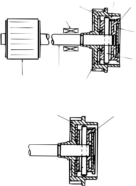
2.5.1Explanation of Each Process Operation
(1)Hopping
As shown in the figure below, the clutch for hopping is turned on/off according to current ON/ OFF to a coil.
When the clutch is OFF
|
Spring for resetting |
Hopping gear |
Clutch plate |
|
Coil
Magnetic substance plate
Pin
Hopping shaft
Hopping roller
Engagement section
When the clutch is ON
Hopping gear
Clutch plate
When the clutch is on, the hopping gear engages with the clutch plate to rotate the hopping roller.
When the clutch is off, the hopping gear is separated from the clutch plate by the spring for resetting, disabling the rotation of the hopping roller.
2 - 13
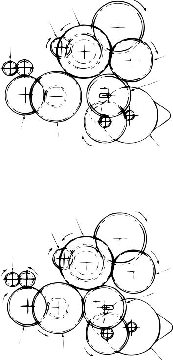
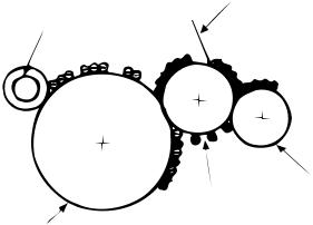
(2) Printing and warm-up
At warm-up
Triple gear
Transfer gear
Resist gear
Idle gear
Planetary gear
a"
 a'
a'
 a
a
Hopping gear
Gear A
Pulse motor (main)
Rotate the pulse motor (main) in the a direction. The planetary gear rotates in the a’ direction, dislocating its position in the a” direction. This causes the planetary gear to be separated from gear A. The hopping gear will not rotate. The triple gear and transfer gear rotate via the idle gear to drive the EP unit.
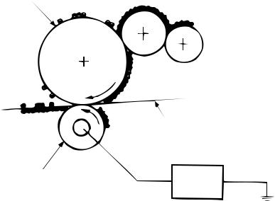
At printing |
Triple gear |
|
Transfer gear |
|
Resist gear |
Idle gear
Planetary gear
b"
 b'
b'
 b
b
Hopping gear
Gear A
Pulse motor (main)
The paper is further advanced in synchronization to the print data.
2 - 14
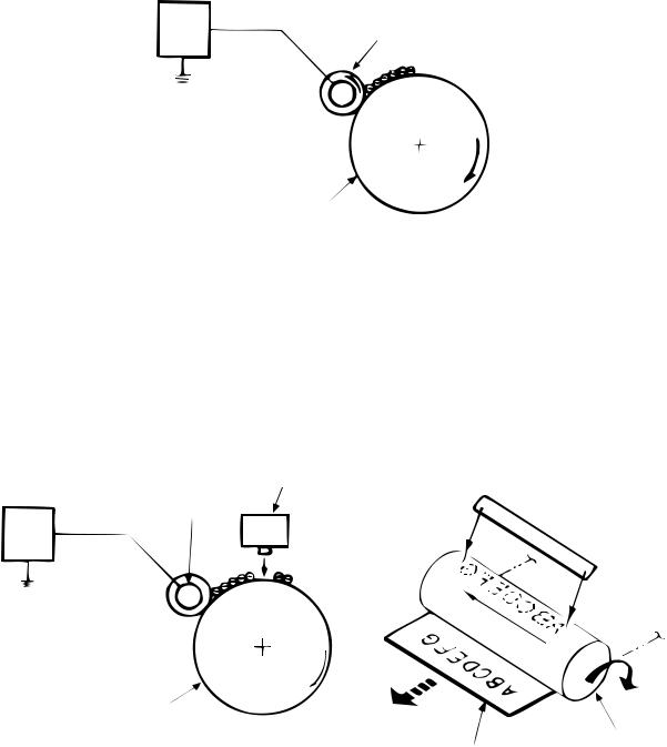
(3)Charging
Charging is performed by applying DC voltage to the charge roller that is in contact with the surface of the OPC drum.
Highvoltage
power Charge roller supply
OPC drum
(4)Exposure
Light emitted from the LED head irradiates the negatively charged surface of the OPC drum. The surface potential of the irradiated surface attenuates to form the electrostatic latent image corresponding to the image signal.
LED head
LED head Charge roller 
Highvoltage power
supply
OPC drum
OPC drum
Paper
2 - 15
(5)Development
The electrostatic latent image on the surface of the OPC drum is changed to a visible toner image by applying a toner to it. Development is performed in the contact part between the OPC drum and developing roller.
1 The sponge roller negatively charges a toner and applies it to the developing roller.
Developing blade
Charge roller
Sponge roller
Developing roller
OPC drum
2 The toner applied to the developing roller is thin-coated by the developing blade.
3A toner adheres to the exposure part of the OPC drum in the contact part between the OPC drum and developing roller. This causes the electrostatic latent image to be changed to a visible image.
2 - 16
(6)Transfer
The transfer roller is composed of conductive sponge material. This roller is set so that the surface of the OPC drum and sheets of paper will adhere closely.
A sheet of paper is placed on the surface of the OPC drum and the positive charge opposite to the negative charge of a toner is applied from the reverse side by the transfer roller.
When a high negative voltage is applied from the power supply to the transfer roller, the positive charge induced on the surface of the transfer roller moves to the paper side at the contact part between the transfer roller and the sheet of paper. The positive charge on the lower side of the sheet of paper then causes the negatively charged toner adhering to the surface of the OPC drum to move to the upper side of the sheet. This enables transfer to the sheet of paper.
OPC drum
Paper
Transfer roller |
High-voltage |
|
power supply |
2 - 17
Loading...