


Ohaus PX3202M, PX2201, PX323M, PX423, PX8201 User Manual
...Pioneer
PX Series Balances
Instruction Manual

PX Series Balance EN-1
Table of Contents
1. |
INTRODUCTION.............................................................................................................. |
EN-3 |
||
|
1.1 |
Description ............................................................................................................................................. |
EN-3 |
|
|
1.2 |
Features ................................................................................................................................................. |
EN-3 |
|
|
1.3 |
Definition of Signal Warnings and Symbols........................................................................................... |
EN-3 |
|
2. |
1.4 |
Safety Precautions................................................................................................................................. |
EN-3 |
|
INSTALLATION ............................................................................................................... |
EN-4 |
|||
|
2.1 |
Unpacking .............................................................................................................................................. |
EN-4 |
|
|
2.2 |
Select the Location ................................................................................................................................ |
EN-4 |
|
|
2.3 |
Leveling.................................................................................................................................................. |
EN-4 |
|
|
2.4 |
Connecting Power and Acclimating the Balance................................................................................... |
EN-5 |
|
|
2.5 |
Connecting the Interface........................................................................................................................ |
EN-5 |
|
|
2.6 |
Initial Calibration .................................................................................................................................... |
EN-5 |
|
3. OPERATION .................................................................................................................... |
EN-6 |
|||
|
3.1 |
Overview of Display, Home Screen ....................................................................................................... |
EN-6 |
|
|
3.2 |
Principal Functions and Main Menu....................................................................................................... |
EN-7 |
|
|
3.3 |
Overview of Parts and Features – Draft Shield Models......................................................................... |
EN-7 |
|
4. |
3.4 |
Overview of Parts and Features – Non-Draft Shield Models................................................................. |
EN-7 |
|
APPLICATIONS............................................................................................................... |
EN-8 |
|||
|
4.1 |
Weighing ................................................................................................................................................ |
EN-8 |
|
|
4.2 |
Parts Counting ....................................................................................................................................... |
EN-8 |
|
|
4.3 |
Percent Weighing................................................................................................................................. |
EN-10 |
|
|
4.4 |
Dynamic Weighing ............................................................................................................................... |
EN-11 |
|
|
4.5 |
Density Determination.......................................................................................................................... |
EN-12 |
|
|
4.5.1 |
Measuring the Density of a Sinking Solid Using Water ................................................................... |
EN-17 |
|
|
4.5.2 |
Measuring the Density of a floating Solid Using Water.................................................................... |
EN-18 |
|
|
4.5.3 |
Measuring the Density of a Solid Using an Auxiliary Liquid other than Water ................................ |
EN-18 |
|
|
4.5.4 |
Measuring the Density of a Liquid Using a Calibrated Sinker ......................................................... |
EN-19 |
|
|
4.5.5 |
Measuring the Density of Porous Material Using Oil ....................................................................... |
EN-21 |
|
|
4.6 |
Additional Features .............................................................................................................................. |
EN-23 |
|
5. MENU SETTINGS.......................................................................................................... |
EN-24 |
|||
|
5.1 |
Menu Navigation .................................................................................................................................. |
EN-24 |
|
|
5.1.1 |
|
Changing Settings............................................................................................................................ |
EN-24 |
|
5.2 |
Calibration............................................................................................................................................ |
EN-24 |
|
|
5.2.1 |
Calibration Sub-menu (InCal models).............................................................................................. |
EN-24 |
|
|
5.2.2 |
Internal Calibration (not applicable to ExCal models)...................................................................... |
EN-25 |
|
|
5.2.3 |
InCal Adjust (not applicable to ExCal models)................................................................................. |
EN-25 |
|
|
5.2.4 |
|
Span Calibration............................................................................................................................... |
EN-25 |
|
5.2.5 |
|
Linearity Calibration ......................................................................................................................... |
EN-26 |
|
5.3 |
Balance Setup...................................................................................................................................... |
EN-28 |
|
|
5.3.1 |
|
Language ......................................................................................................................................... |
EN-28 |
|
5.3.2 |
|
Filter Level........................................................................................................................................ |
EN-28 |
|
5.3.3 |
AZT (Auto Zero Tracking) ................................................................................................................ |
EN-28 |
|
|
5.3.4 |
|
Auto Tare ......................................................................................................................................... |
EN-28 |
|
5.3.5 |
|
Graduations...................................................................................................................................... |
EN-29 |
|
5.3.6 |
|
Date Format ..................................................................................................................................... |
EN-29 |
|
5.3.7 |
|
Date Setup ....................................................................................................................................... |
EN-29 |
|
5.3.8 |
|
Time Format..................................................................................................................................... |
EN-29 |
|
5.3.9 |
|
Time Setup....................................................................................................................................... |
EN-29 |
|
5.3.10 |
Brightness ........................................................................................................................................ |
EN-29 |
|
|
5.3.11 |
Auto Dim .......................................................................................................................................... |
EN-29 |
|
|
5.3.12 |
Capacity Bar..................................................................................................................................... |
EN-29 |
|
|
5.3.13 |
Approved Mode................................................................................................................................ |
EN-30 |
|
|
5.4 |
Weighing Units..................................................................................................................................... |
EN-30 |
|
|
5.5 |
RS232 Interface Setup......................................................................................................................... |
EN-32 |
|
|
5.5.1 |
|
Baud Rate ........................................................................................................................................ |
EN-32 |
|
5.5.2 |
|
Transmission.................................................................................................................................... |
EN-32 |
EN-2 |
|
|
PX Series Balance |
5.5.3 |
|
Handshake....................................................................................................................................... |
EN-33 |
5.6 |
Print Settings........................................................................................................................................ |
EN-33 |
|
5.6.1 |
|
Stable Only....................................................................................................................................... |
EN-33 |
5.6.2 |
|
Numeric Only ................................................................................................................................... |
EN-33 |
5.6.3 |
|
Single Header .................................................................................................................................. |
EN-33 |
5.6.4 |
|
Print To............................................................................................................................................. |
EN-33 |
5.6.5 |
|
Auto Print ......................................................................................................................................... |
EN-33 |
5.6.6 |
|
Header ............................................................................................................................................. |
EN-33 |
5.6.7 |
|
Date and Time.................................................................................................................................. |
EN-33 |
5.6.8 |
|
Balance ID........................................................................................................................................ |
EN-34 |
5.6.9 |
|
Balance Name.................................................................................................................................. |
EN-34 |
5.6.10 |
User Name....................................................................................................................................... |
EN-34 |
|
5.6.11 |
Project Name ................................................................................................................................... |
EN-34 |
|
5.6.12 |
Application Name............................................................................................................................. |
EN-34 |
|
5.6.13 |
Result ............................................................................................................................................... |
EN-34 |
|
5.6.14 |
Gross................................................................................................................................................ |
EN-34 |
|
5.6.15 |
Net.................................................................................................................................................... |
EN-34 |
|
5.6.16 |
Tare.................................................................................................................................................. |
EN-34 |
|
5.6.17 |
Line Feed ......................................................................................................................................... |
EN-34 |
|
5.7 |
GLP ...................................................................................................................................................... |
EN-35 |
|
5.7.1 |
|
Header ............................................................................................................................................. |
EN-35 |
5.7.2 |
|
Balance Name.................................................................................................................................. |
EN-35 |
5.7.3 |
|
User Name....................................................................................................................................... |
EN-35 |
5.7.4 |
|
Project Name ................................................................................................................................... |
EN-35 |
5.8 |
Factory Reset....................................................................................................................................... |
EN-35 |
|
5.9 |
Lockout................................................................................................................................................. |
EN-35 |
|
6. LEGAL FOR TRADE (LFT) ........................................................................................... |
EN-36 |
||
6.1 |
Settings ................................................................................................................................................ |
EN-36 |
|
6.2 |
Verification ........................................................................................................................................... |
EN-36 |
|
6.3 |
Securing the Menu............................................................................................................................... |
EN-36 |
|
6.4 |
Sealing Access to the Balance Settings .............................................................................................. |
EN-36 |
|
7. Printing.......................................................................................................................... |
EN-37 |
||
7.1 |
Connecting, Configuring and Testing the Printer / Computer Interface............................................... |
EN-37 |
|
7.2 |
Output Format...................................................................................................................................... |
EN-38 |
|
7.3 |
Printout Examples................................................................................................................................ |
EN-38 |
|
8. MAINTENANCE............................................................................................................. |
EN-40 |
||
8.1 |
Calibration............................................................................................................................................ |
EN-40 |
|
8.2 |
Cleaning............................................................................................................................................... |
EN-40 |
|
8.3 |
Troubleshooting ................................................................................................................................... |
EN-40 |
|
8.4 |
Service Information .............................................................................................................................. |
EN-40 |
|
9. TECHNICAL DATA........................................................................................................ |
EN-41 |
||
9.1 |
Specifications....................................................................................................................................... |
EN-41 |
|
9.2 |
Drawings and Dimensions ................................................................................................................... |
EN-46 |
|
9.3 |
Accessories.......................................................................................................................................... |
EN-46 |
|
9.4 |
Communication .................................................................................................................................... |
EN-47 |
|
9.4.1 |
|
Interface Commands........................................................................................................................ |
EN-47 |
9.4.2 |
RS232 (DB9) Pin Connections ........................................................................................................ |
EN-48 |
|
9.4.3 |
|
USB Interface................................................................................................................................... |
EN-48 |
9.4.4 |
|
USB Connection............................................................................................................................... |
EN-49 |
10.SOFTWARE UPDATES................................................................................................. |
EN-49 |
||
11.COMPLIANCE ............................................................................................................... |
EN-50 |
||
PX Series Balance |
EN-3 |
1.INTRODUCTION
1.1Description
The PX balance is a precision weighing instrument that will provide you with years of service if properly cared for. PX balances are available in capacities from 82 grams to 8200 grams.
1.2Features
Operation Controls: 2-line backlit display, with 6 weighing applications and many other features.
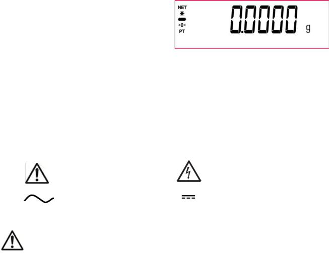
1.3Definition of Signal Warnings and Symbols
Safety notes are marked with signal words and warning symbols. These show safety issues and warnings. Ignoring the safety notes may lead to personal injury, damage to the instrument, malfunctions and false results.
WARNING |
For a hazardous situation with medium risk, possibly resulting in injuries or |
CAUTION |
death if not avoided. |
For a hazardous situation with low risk, resulting in damage to the device or |
|
Attention |
the property or in loss of data, or injuries if not avoided. |
For important information about the product |
|
Note |
For useful information about the product |
Warning Symbols |
|
General Hazard |
Electrical Shock Hazard |
Alternating Current |
Direct Current |
1.4Safety Precautions
CAUTION: Read all safety warnings before installing, making connections, or servicing this equipment.
Failure to comply with these warnings could result in personal injury and/or property damage. Retain all instructions for future reference.
Verify that the AC adapter’s input voltage range and plug type are compatible with the local AC main power supply.
Make sure that the power cord does not pose a potential obstacle or tripping hazard.
Do not position the balance such that it is difficult to reach the power connection.
The balance is for indoor use only. Do not operate the equipment in hazardous or unstable environments.
Operate the equipment only under ambient conditions specified in these instructions.
Do not drop loads on the pan.
Use the balance only in dry locations.
Disconnect the equipment from the power supply when cleaning.
Use only approved accessories and peripherals.
Service should only be performed by authorized personnel.
EN-4 |
PX Series Balance |
2.INSTALLATION
2.1 Unpacking
Carefully remove your PX balance and each of its components from the package. The included components vary depending on the balance model (see the list below). Save the packaging to ensure safe storage and transport. Please read the manual completely before installing and using the PX balance to avoid incorrect operation.
Components included:
Balance
Power adapter + Attaching plug
Stainless steel pan
Pan support (for 0.1 g / 0.01 g model only)
Warrenty card
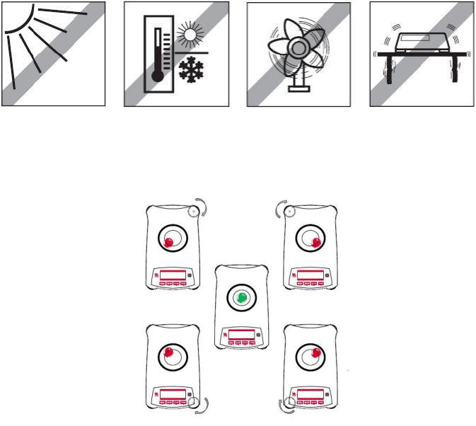
2.2Select the Location
Avoid heat sources, rapid temperature changes, air current or excessive vibrations. Allow sufficient space.
2.3 Leveling
Be sure the balance is level before it is used or after its location is changed. The PX balance has a level bubble in a small round window beside the display.
To level the balance, adjust the 4 Leveling Feet until the bubble is centered in the circle. Please refer to Figure 2-1 for leveling.
Figure 2-1. Leveling
PX Series Balance |
EN-5 |
2.4 Connecting Power and Acclimating the Balance
Connect the DC output connector to the power receptacle on the rear of the balance. Then connect the AC adapter plug to a suitable electrical outlet.
Acclimating
It is suggested that the balance should not be used until it has been connected to power and acclimated to the environment for a certain period of time. In the case of balance with the precision above 0.1 mg, the acclimation time should be 1.5 hours; in the case of balance with the precision of 0.01 mg, the acclimation time should be more than 4 hours.
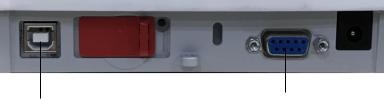
2.5 Connecting the Interface
The PX balance has two data interfaces, RS232 and USB.
Use the RS-232 port to connect either to a computer or a printer with a standard (straight-through) serial cable. Use the USB port to connect to a computer with a USB 2.0 Type A to Type B cable.
Interface connections on the rear of the balance
USB |
RS232 |
|
USB Used to connect to PC only RS232 Used to connect to PC or Printer
Note: For Connecting, Configuring and Testing the Printer / Computer Interface, see the Printing section.
2.6 Initial Calibration
When the PX balance is first installed, or when it is moved to another location, it must be calibrated to ensure accurate weighing results. PX balances are classified into two categories, InCal models and ExCal models. InCal models have a built-in calibration mechanism which can calibrate the balance automatically and does not require the use of external calibration masses. If preferred, InCal models can also be manually calibrated with external masses. ExCal models are calibrated with external masses. Make sure to have the appropriate calibration masses available before beginning calibration.
EN-6 |
PX Series Balance |
3.OPERATION
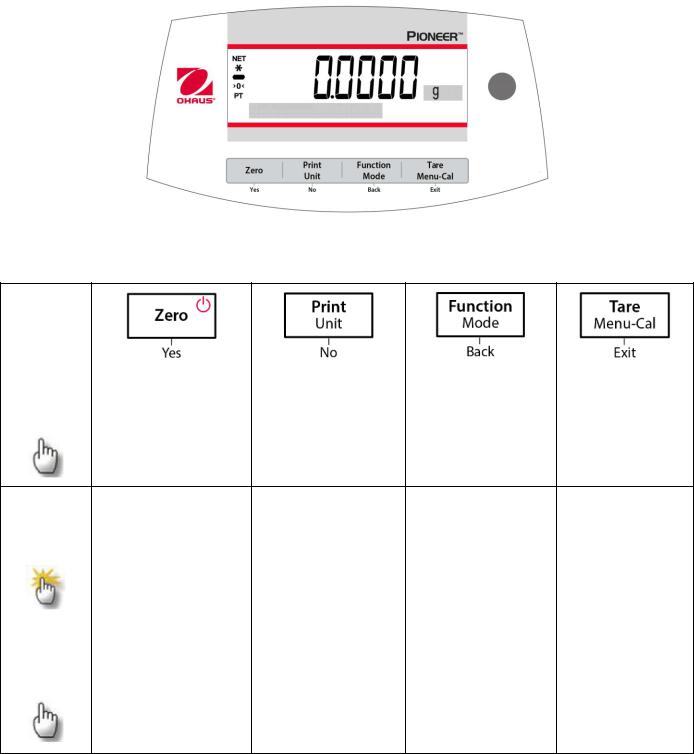
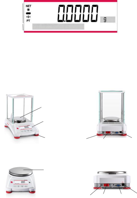
3.1Overview of Display, Home Screen
The PX balance has a 2-line backlit display.
CONTROLS
CONTROL FUNCTIONS
Button |
|
|
|
|
|
|
|
|
|
|
|
|
|
Primary |
|
On / Zero |
Function |
Tare |
||
|
|
|
|
|
||
Function |
|
If the Indicator is |
Sends the current |
Operation is |
Performs tare |
|
(Short |
||||||
|
Off, turns on the |
displayed value to |
dependent on the |
operation. |
||
Press) |
|
|||||
|
Indicator. |
the serial interface. |
application mode. |
|
||
|
|
|
||||
|
If Indicator is On, |
|
|
|
||
|
|
sets zero. |
|
|
|
|
Secondary |
Off |
Unit |
Mode |
|
Menu-Cal |
Zeroing current |
Changes weighing |
Changes |
|
Enters the main |
|
Function |
|
||||
(Press and |
value. |
units. |
application mode. |
|
menu. |
Hold) |
|
|
|
|
Calibration is |
|
|
|
|
|
the first sub- |
|
|
|
|
|
menu. |
|
|
|
|
|
Views the preset |
|
|
|
|
|
Tare value. |
Menu |
Yes |
|
No |
|
Back |
|
Exit |
|
|
|
|
|
|
|
|
Function |
Accepts the current |
|
Rejects the current |
|
Reverts back to |
|
Immediately |
(Short |
(blinking) setting on |
|
(blinking) setting |
|
previous menu |
|
exits the sub- |
Press) |
the display. |
|
on the display. |
|
item. |
|
menu. |
|
|
|
Increments a value |
|
Decrements a |
|
Aborts a |
|
|
|
being entered. |
|
value being |
|
calibration in |
|
|
|
|
|
entered. |
|
progress. |
PX Series Balance |
|
EN-7 |
MAIN APPLICATION SCREEN |
|
|
Net (NET) |
|
Result Field: |
|
||
Stability (*) |
|
Information varies |
Negative (-) |
|
by application |
Centre of Zero (>0<) |
|
|
Pre-tare (PT) |
|
Unit |
Instructional Messages |
|
|
3.2Principal Functions and Main Menu
Weighing: |
Press Zero to set the display to zero. Place an object on the pan. The display indicates the gross |
|
weight. |
Taring: |
With no load on the pan, press Zero to set the display to zero. Place an empty container on the |
|
pan and press Tare. Add material to the container and its net weight is displayed. After the |
|
container and the objects are removed, the load will be displayed as a negative number. Press |
|
Tare to clear. |
Zero: |
Press Zero to zero the balance. |
Dot-matrix |
The relevant data in the specific application mode are shown in the dot-matrix display area. |
Display: |
|
3.3Overview of Parts and Features – Draft Shield Models
|
|
Pan |
|
|
|
|
|
|
Level Indicator |
|
|
|
|
Adjustable |
|
Adjustable |
USB |
|
|
|
|
|
|
|
|||
Foot |
|
|
|
Power Input |
||
|
Foot |
Device |
Security Switch |
|
||
|
|
|
|
RS232 |
||
3.4Overview of Parts and Features – Non-Draft Shield Models
Pan
|
|
|
|
USB |
Security Switch RS232 Power Input |
|
|
|
|
Device |
|
Adjustable Foot |
Adjustable Foot |
|
|||
|
|
||||
EN-8 |
PX Series Balance |
4.APPLICATIONS
The PX balance can be operated in 6 application modes by long pressing the Function / Mode button.
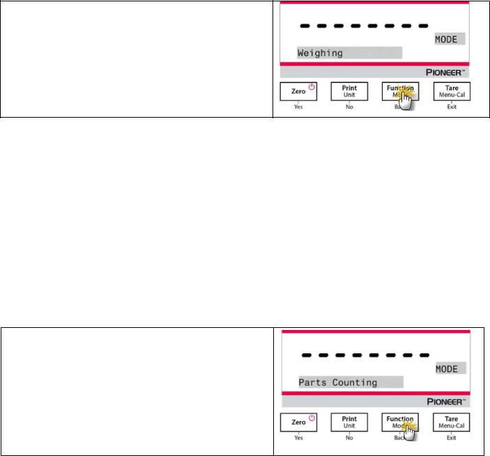
4.1Weighing
Note: Before using any application, be sure the balance has been leveled and calibrated. Use this application to determine the weight of objects in the selected unit of measure.
Weighing
1.Press Tare or Zero if necessary to begin.
2.Press and hold the Function / Mode button to select Weighing (this application is the default).
3.Place objects on the pan to display the weight. Once the reading is stable, the * will appear.
4.The resulting value is displayed in the active unit of measure.
Item Settings
To view or adjust the current settings.
•Capacity Bar: When set to On, the capacity bar is displayed in the reference field. The capacity will not display when the balance is set to zero.
•Weighing Units: Change the displayed unit. See Section 5.4 for more information.
•Filter Level: Change Filtering level. See Section 5.3.2 for more information.
•GLP Data: See Section 5.7 for more information.
•Print Settings: Change printing settings. See Section 7 for more information.
4.2Parts Counting
Note: Before using any application, be sure the balance has been leveled and calibrated. The minimum piece weight should be no less than 0.1d.
Use this application to count samples of uniform weight.
Parts Counting
1.Press Tare or Zero if necessary to begin.
2.Press and hold the Function / Mode button until
Parts Counting appears.
PX Series Balance |
EN-9 |
3.After confirmation by pressing Yes, the message
"Clear APW?" will appear on the screen.
4.If the APW of the last Parts Counting operation needs to be kept, press No when the message "Clear APW?" displays.
5.Press Yes, and the message "Sample size 10" will display with the numeral "10" (default) flashing.
6.Confirm the sample size by pressing Yes, and place 10 samples on the pan to display the weight. Press No or Back to increase or decrease the value as desired.
7.Press the Function / Mode button so that the weight of the 10 samples is used to establish the average piece weight (APW). The display will show 10 pieces.
8.To view the piece weight or the total weight, press the
Function / Mode button.
9.Place additional objects on the pan, and the corresponding number of pieces will display.
Item Settings
Sample: The sample size ranges from 1 to 1000. The default value is 10.
Note: To ensure accurate counting, the minimum piece weight should be no less than 0.1d.
EN-10 |
PX Series Balance |
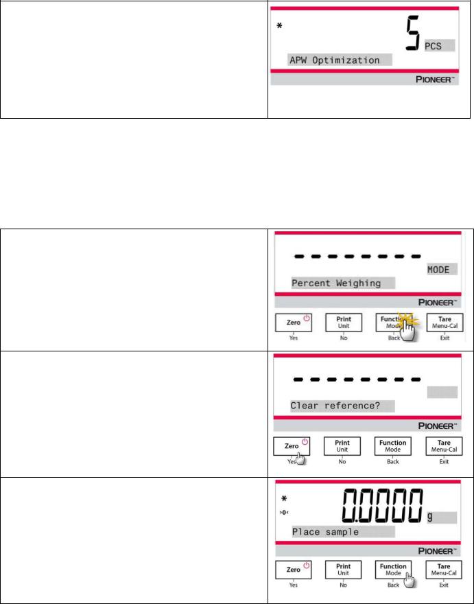
APW Optimization:
Improving counting accuracy by re-calculating the piece weight automatically as parts are added.
APW Optimization occurs only when the number of pieces added to the pan is between one and three times the number already on the pan.
Print Settings:
Changing printing setup. See Section 7 for more information.
4.3Percent Weighing
Note: Before using any application, be sure the balance has been leveled and calibrated.
Use Percent Weighing to display the weight of a test object as a percentage of a pre-established reference sample.
The default (or last) reference weight is displayed.
Percent Weighing
1.Press and hold the Function / Mode button until
Percent Weighing appears.
2.After confirmation by pressing Yes, the message
"Clear reference?" will appear on the screen.
3.Press Yes, and then the message "Place sample" will display.
4.Place the reference sample on the pan to display the weight. When the reading is stable, the * will appear.
5.Press the Function / Mode button so that the weight of the reference sample is stored in memory. The display will show 100%.

PX Series Balance |
EN-11 |
6.Remove the reference sample and place the test object on the pan. The ratio of the test object to the reference sample weight is displayed as a percentage.
7.To view the reference sample weight or the test object weight, press the Function / Mode button.
Item Settings
Note:
If the previously established reference sample weight needs to be kept, press No when the message "Clear reference?" displays.
Printing Setup:
Changing printing setup. See Section 7 for more information.
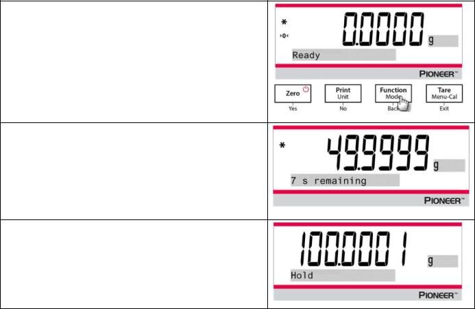
4.4Dynamic Weighing
Note: Before using any application, be sure the balance has been leveled and calibrated. Clear the pan before beginning a new Dynamic Weighing cycle.
Use this application to weigh an unstable load, such as a moving animal.
Dynamic Weighing
1.Press and hold the Function / Mode button until
Dynamic Weighing appears.
2.After confirmation by pressing Yes, the message "Change parameter?" will appear on the screen.
3.Press Yes, and then the message "Average time 10 s" will display with the numeral "10" flashing. Press No or Back to increase or decrease the value as desired.
EN-12 |
PX Series Balance |
4.Confirm the weighing time by pressing Yes, and the message "Ready" will display at the lower left of the screen.
5.Place the dynamic object on the pan. The balance begins a countdown (averaging process). During the countdown, the screen shows the time remaining.
6.When the countdown ends, the result line is displayed and held.
7.After the dynamic object is removed, the weight will be automatically set to zero, and the balance will return to the status of "Ready".
Item Settings
1.Averaging Time: Set the averaging time to a value between 1 and 15 seconds. Default is 10 seconds.
2.Printing Setup: Changing printing setup. See Section 7 for more information.
4.5Density Determination
Note: Before using any application, be sure the balance has been leveled and calibrated. Use this application to determine an object’s density.
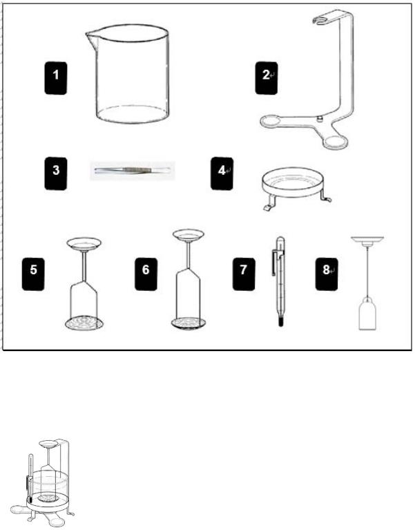
A Density Determination Kit, Part Number 80253384, is designed to be used with PX series balances. Illustrations in this procedure refer to the density kit, however, you may use whatever lab apparatus that will suit the requirements for density measurements. A built in reference density table for water at temperatures between 10ºC and 30.9ºC is included in the balance software. Review this entire section before attempting density measurements.
PX Series Balance |
EN-13 |
1. |
Glass beaker |
2. |
Bracket |
3. |
Forceps |
4. |
Platforms |
5. |
Holder for floating solids |
6. |
Holder for non floating solids |
7. |
Precision thermometer with holder |
8. |
Sinker 10ml (optional equipment) |
When making density measurements, the material should weigh at least 10.0 mg on an analytical balance and 100 mg on a precision balance.
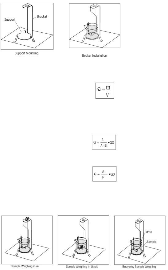
Balance Preparation with Ohaus Density Kit (Optional)
Allow the balance to warm up sufficiently before making measurements.
Open either the left or right side door of the balance and remove the Pan as shown. Insert the Bracket into the balance where the Pan was removed.
The Equalizing Washer is not used.
EN-14 |
PX Series Balance |
Place the Support into position over the bracket making sure the Support does not make contact with the Bracket as shown in illustration.
Install beaker on support as shown.
NOTE: Beaker and thermometer are not supplied as part of the density kit.
The density Q is the quotient of the mass m and the volume V.
Density determinations are performed by using Archimedes’ principle. This principle states that every solid body immersed in a fluid loses weight by an amount equal to that of the fluid it displaces. The density table for water is included in the Discovery balance software.
The density of a solid is determined with the aid of a liquid whose density, Qo, is known (water is used as an auxiliary liquid). The solid is weighed in air (A) and then in the auxiliary liquid (B). The density Q can be calculated from the two weighings as follows:
The balance allows direct determination of the buoyancy P (P =A - B) and consequently the above formula can be simplified:
Q = Density of the solid
A = Weight of the solid in air
B = Weight of the solid in the auxiliary liquid
Q0 = Density of the auxiliary liquid at a given temperature (this value depends on the temperature). The density table for water is included in Discovery balances.
P = Buoyancy of the solid in the auxiliary liquid (corresponds to A-B).
PX Series Balance |
EN-15 |
Place the solid in the Weighing Pan on the Weigh Below Hook in the liquid as shown. Ensure that there are no air bubbles on the solid to be weighed.
Close the draft shield doors and weigh the solid (buoyancy P). The display indicates the density in grams/cc.
Solid Density Determinations for items Less Density Than Water
For density determination of solids with a density less than 1 g/CM3, the bottom of the Weigh Below Hook for solids must be used as it holds the solid body below the surface of the auxiliary liquid. If the buoyancy of the solid is greater than the weight of the Weigh Below Hook, the Weigh Below Hook must be weighted by placing an additional mass on the submerged part of the Weigh Below Hook as shown.
Weigh the sample in air first as explained in the previous procedure.
After loading the additional mass, tare the balance and start the weighing again. Wait until the balance has reached stability and note the displayed weight P (buoyancy of the solid).
Improving the Accuracy of the Result of Solid Density
The following tips should help you improve the accuracy of the results in the density determination of solids.
Temperature
Solids are generally so insensitive to temperature fluctuations that the corresponding density changes are of no consequence. However, as work is performed with an auxiliary liquid in the density determination of solids, their temperature must be taken into account as the temperature has a greater effect with liquids and causes density changes in the order of magnitude 0.5 to 1% per °C. This effect is already apparent in the third decimal place of the result.
To obtain accurate results, we recommend that you always take the temperature of the auxiliary liquid into account on all density determinations.
Air Buoyancy
1 CM3 of air weighs approximately 1.2 mg (depending on the physical condition). As a consequence, in the weighing in air, each solid experiences buoyancy of this magnitude (the so-called “air buoyancy”) per cm3 of its volume.
However, the air buoyancy must be taken into account only when a result is required with an accuracy of 3 to 4 decimal places. To correct for this, the air buoyancy (0.0012 g per cm3 volume of the body) is added to the calculated result:
Calculated density + 0.0012 g/cm3 air buoyancy = effective density
Surface tension of the auxiliary liquid
Adhesion of the liquid to the Weigh Below Hook causes an apparent weight increase of up 3 mg.
As the Weigh Below Hook is immersed in the auxiliary liquid in both weighings of the solid (in air and in the auxiliary liquid), the influence of the apparent weight increase can be neglected because the balance is tared before every measurement.
To reduce the effect of air bubbles and to ensure the greatest possible accuracy, use a few drops of a wetting agent (not supplied) and add them to the auxiliary liquid.
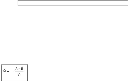
Liquid Density Determinations
The density of a liquid can be made using a sinker of known volume. The sinker (P/N: 83034024) is weighed in air and then in the liquid whose density is to be determined, The density, Q, can be determined from the two weighings as follows:
Q = Density of the liquid
A = Weight of the sinker in air
B = Weight of the sinker in liquid
V = Volume of the sinker
P = Buoyancy of the sinker in the liquid (P = A-B)
 Loading...