


Instruction Manual
MB35 Moisture Analyzer
Manual de instrucciones Analizador de humedad MB35
Guide d’utilisateur Analyseur d’humidité MB35

MB35 EN-1
Contents
1. |
INTRODUCTION ..................................................................................................... |
EN-2 |
1.1 |
Safety Precautions ...................................................................................................... |
EN-2 |
2. |
INSTALLATION .......................................................................................................... |
EN-4 |
2.1 |
Unpacking and Checking Equipment.............................................................................. |
EN-4 |
2.2 |
Selecting the Location .................................................................................................. |
EN-4 |
2.3 |
Installing the Heat Shield, Draft Shield and Pan Support ................................................... |
EN-4 |
2.4 |
Connecting to a Power Supply ...................................................................................... |
EN-5 |
2.5 |
Operating Controls ...................................................................................................... |
EN-6 |
3. |
MOISTURE ANALYZER SETUP ..................................................................................... |
EN-7 |
3.1 |
Language Settings ...................................................................................................... |
EN-7 |
3.2 |
Weight Calibration ...................................................................................................... |
EN-8 |
3.3 |
Temperature Calibration ............................................................................................... |
EN-9 |
3.4 |
Time and Date Setting................................................................................................ |
EN-10 |
3.5 |
RS232 Settings......................................................................................................... |
EN-11 |
3.6 |
Setting Print and GLP Printing On or Off........................................................................ |
EN-12 |
3.7 |
Adjusting Display Contrast and Brightness .................................................................... |
EN-13 |
4. |
OPERATING YOUR MOISTURE ANALYZER ................................................................... |
EN-14 |
4.1 |
Setting the Drying Temperature.................................................................................... |
EN-14 |
4.2 |
Setting the Drying Time .............................................................................................. |
EN-14 |
4.3 |
Sample Preparation................................................................................................... |
EN-14 |
4.4 |
Running the Test ....................................................................................................... |
EN-15 |
4.5 |
RS232 Command Table ............................................................................................ |
EN-16 |
5. |
CARE AND MAINTENANCE ........................................................................................ |
EN-17 |
5.1 |
Cleaning Interior/Exterior Components .......................................................................... |
EN-17 |
5.2 |
Replacing Power Line Fuse ........................................................................................ |
EN-18 |
5.3 |
Resetting the Dryer Thermal Overload Device ................................................................ |
EN-18 |
5.4 |
Accessories.............................................................................................................. |
EN-19 |
5.5 |
Specifications ........................................................................................................... |
EN-19 |
6. |
COMPLIANCE .......................................................................................................... |
EN-20 |

EN-2 |
MB35 |
|
|
|
|
1. Introduction
Thank you for deciding to purchase a MB35 Halogen Moisture Analyzer from Ohaus. Behind your instrument stands OHAUS, a leading manufacturer of precision Moisture Analyzers, Balances, Scales and Indicators. An Aftermarket Department with trained instrument technicians is dedicated to provide you with the fastest service possible in the event your instrument requires servicing.
1.1 Safety Precautions
Your Moisture Analyzer employs state of the art technology and meets the latest demands regarding instrument safety. Improper operation can endanger personnel and can cause property damage. For safe and dependable operation, please comply with the following instructions:
—The Moisture Analyzer is used for determination of the moisture in samples. Please use the instrument exclusively for this purpose. Any other type of use can endanger personnel and damage the instrument or other property.
—The Moisture Analyzer must not be operated in a hazardous environment and only under ambient conditions specified in these instructions.
—The Moisture Analyzer may be operated only by trained personnel who are familiar with the properties of the samples used and with the handling of the instrument.
—Your Moisture Analyzer is supplied with a 3-pin power cable with an equipment grounding conductor is prohibited.
The Halogen Moisture Analyzer works with heat!
—Ensure sufficient free space around the instrument to avoid heat accumulation and overheating (approximately 1 m free space above the instrument).
—Never place flammable materials on, below or next to the instrument as the area around the dryer unit warms up.
—Exercise caution when removing the sample. The sample itself, the sample chamber and any sample containers may still be very hot.
—During operation, you should never open the dryer unit as the ring-shaped heating element or completely.

MB35 |
EN-3 |
|
|
|
|
1.1 Safety Precautions (Cont.)
Certain samples require special care!
With certain types of samples, there is a possibility of danger to personnel or damage to property through:
Fire or explosion:
— Flammable or explosive substances;
—Substances containing solvents;
—Substances which release flammable or explosive vapors when heated. With such samples, work at a drying temperature that is low enough to prevent the formation of flames or an explosion and wear protective goggles. Should there be any uncertainty regarding the flammability of a sample, always work with a small sample (maximum. 1 gram). In such cases, never leave the instrument unattended! In cases of doubt, perform a careful risk analysis.
Poisoning, burning:
—Substances which contain toxic or caustic components. Such substances may be dried only in a fume hood.
Corrosion:
—Substances which release corrosive vapors when heated (e.g. acids). In the case of such substances, we advise you to work with small amounts of samples as the vapor can condense on cooler housing parts and cause corrosion. Please note that the user always takes responsibility and assumes liability for damage caused by use of the types of samples mentioned above!
—Never make any modifications or constructional alterations to the instrument and use only original spare parts and optional equipment from Ohaus Corporation.
—Your Moisture Analyzer is a rugged, precision instrument – but you should still treat it carefully; it will then provide you with many years of trouble-free operation.
—Please comply with all notes and instructions in these operating instructions. Keep the instructions in a safe place where they are immediately at hand if any points are unclear.
APPLICATION DISCLAIMER:
—Moisture determination applications must be optimized and validated by the user according to local regulations. Application specific data provided by Ohaus is provided for reference purposes only. Ohaus waives all liability for applications based on this data.
EN-4 |
MB35 |
|
|
|
|
2. Installation
This section contains unpacking and installation instructions for your new Moisture Analyzer .
2.1 Unpacking and Checking Equipment
Open the package and remove the instrument and the accessories. Check the completeness of the delivery.
The following accessories are part of the standard equipment of your new Moisture Analyzer.
—1 Box, Aluminum sample pans
—1 Pan support
—1 Specimen sample (circular, absorbent cellulose disk)
—1 Draft shield element
—1 Heat shield
—1 Power cable
—1 Set of operating instructions
—1 Warranty card
Remove packing material from the instrument. Check the instrument for transport damage. Immediately inform your Ohaus dealer if you have complaints or parts are missing. Store all parts of the packaging. This packaging guarantees the best possible protection for the transport of your instrument.
2.2 Selecting the Location
The Moisture Analyzer should always be used in an environment which is free from excessive air currents, corrosives, vibration, and temperature or humidity extremes. These factors will affect displayed weight readings.
DO NOT install the Moisture Analyzer next to:
• Open windows or doors or vents causing drafts or rapid temperature changes.
• Near vibrating, rotating or reciprocating equipment.
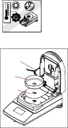
2.3 Installing the Heat Shield, Draft Shield and Pan Support
Pan Support |
Draft Shield |
Heat Shield |
Install the heat shield, draft shield and pan support as shown. Turn the pan support until it engages In the locked position.
MB35 |
EN-5 |
|
|
|
|
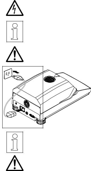
2.4 Connecting to a Power Supply
Check to ensure the voltage identification label on the Moisture Analyzer matches your local line voltage.
The halogen dryer unit is designed to operate at a specific line voltage (120 V ac or 240 V ac).
CAUTION:
Connection to line voltages that are above or below the rated voltage can cause improper operation or damage to the unit.
Connect power cord as shown. The MB35 is operational when power is applied. The display remains off until the On/Off button is pressed.
Allow the Moisture Analyzer to warm up for at least 30 minutes to stabilize when turned on.
WARNING:
If the power cable supplied is not long enough, use only a proper 3-pin extension cable with an equipment grounding connector.
EN-6 |
MB35 |
|
|
|
|
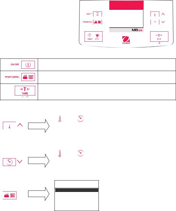
2.5 Operating Controls
The MB35 Moisture Analyzer controls are grouped as operating buttons and function buttons with three modes of operation.
EDIT MODE – User is changing a parameter, no test running.
RUN MODE – Unit is running a test.
RESULT MODE – Final result.
OPERATING BUTTONS
Turns display On or Off.
Press to enter ANALYZER SETUP screen. (Edit mode)
Print Test Result (if COM parameters are set and PRINT is on).
Accepts selection. (Edit mode) Sends Print command. (Run mode)
Performs Tare function. (Pressing during the test has no effect.)
FUNCTION BUTTONS
|
|
|
|
|
|
|
100° |
|
10:00 |
EDIT MODE |
|
|
|
|
ONLY |
|
|
|
|
CLEAR |
|
0.000g |
||
|
|
|||
|
PAN |
|
||
|
PRESS |
|
* |
|
|
TARE |
|
||
|
|
|
||
|
|
|
||
|
|
|
|
|
|
|
100° |
|
10:00 |
EDIT MODE |
|
|
|
|
ONLY |
|
|
|
|
CLEAR |
|
0.000g |
||
|
|
|||
|
PAN |
|
||
|
PRESS |
|
* |
|
|
TARE |
|
||
|
|
|
||
Initial press of button highlights temperature numerals. Additional presses increases temperature setting in 5 degree increments.
Initial press of button highlights shut-off selection. Additional presses step through options, AUTO or TIMED (minutes/seconds).
EDIT MODE
ONLY
ANALYZER SETUP
WEIGHT CAL
TEMP CAL
TIME-DATE
RS-232
EXIT
In a non-run mode, initial press of button brings up the ANALYZER SETUP screen.
MB35 |
EN-7 |
|
|
|
|
3. Moisture Analyzer Setup
3.1 Language Setting
1. START |
|
|
|
|
|
ANALYZER SETUP |
x6 |
ANALYZER SETUP |
|
|
|
|
|
|
|
||||
|
|
|
|
|
|
|
|
|
|
|
|
|
|
|
|
|
TEMP CAL |
||
|
|
|
|
|
|
WEIGHT CAL |
|
||
|
|
|
|
|
|
TEMP CAL |
|
TIME-DATE |
|
|
|
|
|||||||
|
|
|
|
|
|||||
|
|
|
|
|
|||||
|
|
|
|
|
|||||
|
|
|
|
|
|
TIME-DATE |
|
RS-232 |
|
|
|
|
|
|
|
|
|||
|
|
|
|
|
|
RS-232 |
|
||
|
|
|
|
|
|
|
EXIT |
||
|
|
|
|
|
|
EXIT |
|
LANGUAGE |
|
|
|
|
|
|
|
|
|
|
|
LANGUAGE |
|
LANGUAGE |
2. SELECT |
|
|
SELECT LANGUAGE |
or |
SELECT LANGUAGE |
|
|
|
ENGLISH |
|
ESPANOL |
3. ACCEPT |
LANGUAGE |
|
|
|
|
|
||
|
|
|
|
|
|
|
|
|
CHANGE ALL TEXT |
|
|
|
|
|
|||
|
|
|
|
|
|
|||
|
TO |
|
|
or |
|
|||
|
ESPANOL |
|
|
|
|
|
|
|
|
ARE YOU SURE |
|
|
|
|
|
|
|
|
NO |
|
|
|
|
|
||
|
|
|
|
|
|
|
|
|
|
|
|
|
|
|
|
||
4. FINAL |
LANGUAGE |
|
|
|
|
|
||
|
|
100 |
10:00 |
|||||
|
|
|
|
|
|
|||
|
ANALYZER WILL |
|
|
|
|
|
|
|
|
BE RESET |
|
|
|
|
|
|
|
|
|
|
|
LIMPIE |
0. 000g |
|||
|
|
|
|
|
||||
|
|
|
|
|
PLATLLO |
|||
|
|
|
|
|
PULSE |
* |
||
|
|
|
|
|
TARE |
|||
|
|
|
|
|
|
|||
EN-8 |
MB35 |
|
|
|
|
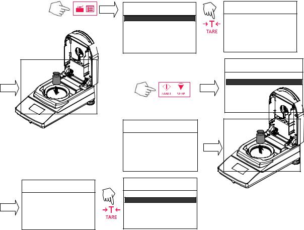
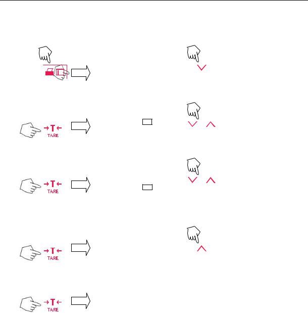
3.2 Weight Calibration
ANALYZER SETUP
WEIGHT CAL
TEMP CAL
TIME-DATE
RS-232
EXIT
TO ABORT:
WEIGHT CAL
REMOVE MASS
TO CONTINUE:
TO ABORT
PRESS STRT/STP KEY
WEIGHT CAL
PRESS TARE
CAL SUCCESSFUL
TO ABORT
PRESS STRT/ STP KEY
ANALYZER SETUP
WEIGHT CAL
TEMP CAL
TIME-DATE
RS-232
EXIT
WEIGHT CAL
PLACE 20G MASS
TO ABORT
PRESS STRT/STP KEY
ANALYZER SETUP
WEIGHT CAL
TEMP CAL
TIME-DATE
RS-232
EXIT

MB35 |
EN-9 |
|
|
|
|
3.3 Temperature Calibration
Note: Temperature Calibration Kit is required.
|
ANALYZER SETUP |
TEMP CAL |
|
LOCK OUT |
|
|
WEIGHT CAL |
REMOVE PAN SUPPORT |
|
TEMP CAL |
|
/ |
|
|
LANGUAGE |
|
|
|
BEEPER |
ABORT CALIBRATION |
|
TIME-DATE |
|
|
|
TEMP CAL
INSERT CAL FIXTURE
CLOSE COVER
ABORT CALIBRATION
TEMP CAL |
|
TEMP CAL 100°C |
TEMP CAL 100°C |
||||
CALIBRATION READY |
|
CURRENT TEMP: |
¾ C |
15 CURRENT TEMP: |
100° C |
||
|
TM TO CAL POINT: |
15:00 MIN |
TM TO CAL POINT: |
15:00 MIN |
|||
|
|
|
|||||
PRESS TARE/ACCEPT |
|
ADJ CAL READING: |
100° C |
ADJ CAL READING: 100° C |
|||
|
|
|
|||||
ABORT CALIBRATION |
|
|
ACCEPT NEW CAL |
ACCEPT NEW CAL |
|||
|
|
ABORT CALIBRATION |
ABORT CALIBRATION |
||||
Adjust to thermometer reading |
|
|
|
|
|
|
|
/ |
|
|
|
|
|
|
|
TEMP CAL 100°C |
|
TEMP CAL 100°C |
|
|
|
||
CURRENT TEMP: |
100° C |
|
|
|
|
||
|
CURRENT TEMP: |
100° C |
|
|
|
||
TM TO CAL POINT: |
15:00 MIN |
|
|
|
|
||
|
TM TO CAL POINT: |
15:00 MIN |
|
|
|
||
|
|
|
|
|
|
||
ADJ CAL READING: |
104° C |
|
ADJ CAL READING: |
104° C |
|
|
|
ACCEPT NEW CAL |
|
|
|
|
|||
|
ACCEPT NEW CAL |
|
Adjust to thermometer reading |
||||
ABORT CALIBRATION |
|
|
|||||
|
ABORT CALIBRATION |
|
/ |
|
|||
|
|
|
|
|
|||
TEMP CAL 160° C |
|
TEMP CAL 160° C |
|
|
|||
15 |
|
TEMP CAL 160° C |
|||||
|
|
|
|
|
|
|
|
CURRENT TEMP: |
160° C |
|
CURRENT TEMP: |
160° C |
|
CURRENT TEMP: |
160° C |
TM TO CAL POINT: |
0:00 MIN |
|
TM TO CAL POINT: |
0:00 MIN |
|
TM TO CAL POINT: |
0:00 MIN |
|
|
|
|
||||
ADJ CAL READING: |
163° C |
|
ADJ CAL READING: |
160° C |
|
ADJ CAL READING: |
163° C |
ACCEPT NEW CAL |
|
ACCEPT NEW CAL |
|
ACCEPT NEW CAL |
|||
ABORT CALIBRATION |
|
|
|||||
|
ABORT CALIBRATION |
|
ABORT CALIBRATION |
||||
ANALYZER SETUP
WEIGHT CAL
TEMP CAL
TIME-DATE
RS-232
EXIT
Open the cover, allow unit to cool, remove the calibration fixture, replace the pan support and pan.
EN-10 |
MB35 |
|
|
|
|
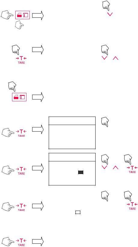
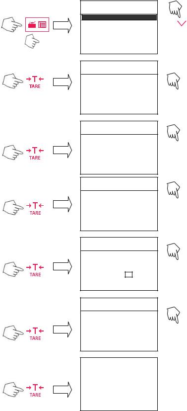
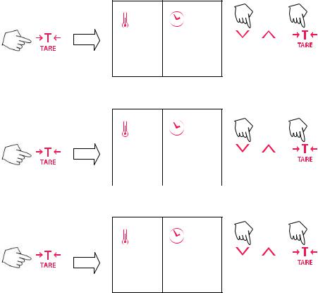
3.4 Time and Date Setting
1. TO START |
|
|
|
|
|
ANALYZER SETUP |
|
|
|
|
|
|
|
|
|
|
|
|
|
|
|
|
|
|
|
|
|
|
|
|
|
|
|
WEIGHT CAL |
|
|
|
|
|
|
TEMP CAL |
|
|
|||||
|
|
|
|
|||
|
|
|
|
|||
|
|
|
|
|||
|
|
|
|
|
|
TIME-DATE |
|
|
|
|
|
|
|
|
|
|
|
|
|
RS-232 |
|
|
|
|
|
|
|
|
|
|
|
|
|
EXIT |
|
|
|
|
|
|
|
2. SET FORMAT |
|
|
TIME - DATE |
|
||||||
|
|
|
|
|
|
|
|
|
|
|
|
|
|
|
|
|
|
|
|
|
|
|
|
|
|
|
|
|
FORMAT: |
MM/DD/YR |
|
|
|
|
|
|
|
|
|
SET DATE: |
07/10/01 |
|
|
|
|
|
|
|
|
|
TIME FMT: |
12HR |
|
|
|
|
|
|
|
|
|
SET TIME: |
11:30 AM |
|
|
|
|
|
|
|
|
|
|
|
|
|
3. Exit without saving |
Only when setting data. |
|
|
|
||||||
|
|
|
|
|
|
|
|
|
||
|
|
|
|
|
|
|
ANALYZER SETUP |
|||
|
|
|
|
|
|
|
|
|
|
|
|
|
|
|
|
|
|
WEIGHT CAL |
|
|
|
|
|
|
|
|
|
|
TEMP CAL |
|
|
|
|
|
|
|
|
|
|
TIME-DATE |
|
|
|
|
|
|
|
|
|
|
|
|
|
|
|
|
|
|
|
|
|
|
|
|
|
|
|
|
|
|
|
|
|
|
|
|
|
|
|
|
|
|
|
|
|
|
|
|
|
|
|
|
|
|
|
|
|
|
|
|
|
|
|
|
|
RS-232 |
|
|
|
|
|
|
|
|
|
|
|
|
|
|
|
|
|
|
|
|
|
EXIT |
|
|
|
|
|
|
|
|
|
|
|
|
|
|
TIME - DATE
4. SET DATE
FORMAT: |
MM/DD/YR |
|
SET DATE: |
07 |
/10/01 |
TIME FMT: |
12HR |
|
SET TIME: |
11:30 AM |
|
|
X2 |
ANALYZER SETUP |
|||
|
|
|
|
|
|
|
WEIGHT CAL |
|
|
|
|
|
|
|
|
|
|
|
|
TEMP CAL |
|
|
|
|
|
TIME-DATE |
|
|
|
|
|
RS-232 |
|
|
|
|
|
|
|
|
|
|
|
EXIT |
|
|
|
|
|
|
|
|
|
|
|
|
|
|
|
|
|
TIME - DATE |
|
||
|
|
|
|
|
|
|
|
|
|
|
|
|
|
FORMAT: |
DD.MM.YR |
|
|
|
|
SET DATE: |
10.07.01 |
|
|
or |
|
TIME FMT: |
12HR |
|
|
|
SET TIME: |
11:30 AM |
|
||
|
|
|
|
|
|
 or
or
Repeat to complete date.
5. SET FMT |
TIME - DATE |
|
|
FORMAT: |
MM/DD/YR |
|
|
|
|
||
|
SET DATE: |
07/10/01 |
or |
|
TIME FMT: |
12HR |
|
|
SET TIME: |
11:30 AM |
Select 12HR or 24HR. |
|
|
|
|
|
TIME - DATE |
|||
6. SET TIME |
|
|
|
|
FORMAT: |
MM/DD/YR |
|||
|
||||
|
SET DATE: |
07/10/01 |
||
|
TIME FMT: |
12HR |
||
|
SET TIME: |
11 |
:30 AM |
|
|
|
|
|
|
7. ACCEPT AND LEAVE |
|
ANALYZER SETUP |
|
|
|
|
WEIGHT CAL |
|
|
|
|
|
|
TEMP CAL |
|
|
TIME-DATE |
|
|
RS-232 |
|
|
|
|
|
EXIT |
|
|
|
 or
or
Repeat for minutes and am/pm.
MB35 |
EN-11 |
|
|
|
|
3.5 RS232 Settings
1.TO START
2.SET BAUD RATE
3.SET PARITY
4.SET DATA BITS
5.SET STOP BITS
6.SET HANDSHAKE
ANALYZER SETUP
WEIGHT CAL
TEMP CAL
TIME-DATE
RS-232
EXIT
RS232
BAUD RATE: |
9600 |
PARITY: |
NONE |
DATA BITS: |
8 |
STOP BITS: |
1 |
HANDSHAKE: |
NONE |
RS232
BAUD RATE: |
9600 |
PARITY: |
NONE |
DATA BITS: |
8 |
STOP BITS: |
1 |
HANDSHAKE: |
NONE |
RS232
BAUD RATE: |
9600 |
|
PARITY: |
NONE |
|
DATA BITS: |
8 |
|
STOP BITS: |
1 |
|
HANDSHAKE: |
NONE |
|
RS232
BAUD RATE: |
9600 |
|
PARITY: |
NONE |
|
DATA BITS: |
8 |
|
STOP BITS: |
1 |
|
HANDSHAKE: |
NONE |
|
RS232
BAUD RATE: |
9600 |
PARITY: |
NONE |
DATA BITS: |
8 |
STOP BITS: |
1 |
HANDSHAKE: |
NONE |
ANALYZER SETUP
7. ACCEPT & LEAVE |
|
|
|
|
WEIGHT CAL |
||
|
|
TEMP CAL |
|
|
|
TIME-DATE |
|
|
|
RS-232 |
|
|
|
|
|
|
|
EXIT |
|
X3 |
|
ANALYZER SETUP |
|
|
|
|
WEIGHT CAL |
|
|
|
|
|
|
TEMP CAL |
|
|
TIME-DATE |
|
|
RS-232 |
|
|
|
|
|
EXIT |
|
|
|
 or
or
Default is 9600.
 or
or
Default is NONE.
 or
or
Default is 8.
 or
or
Default is 1.
 or
or
Default is NONE.
EN-12 MB35
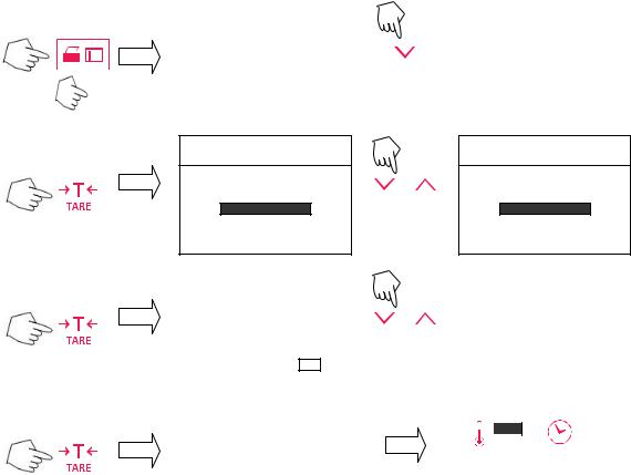
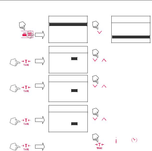
3.6 Setting Print and GLP Printing On or Off
1. To Start: |
ANALYZER SETUP |
|
ANALYZER SETUP |
|
|
|
|||
|
WEIGHT CAL |
|
X4 |
WEIGHT CAL |
|
TEMP CAL |
|
TEMP CAL |
|
|
|
|
||
|
TIME-DATE |
|
|
TIME-DATE |
|
RS-232 |
|
|
RS-232 |
|
|
|
||
|
EXIT |
|
|
EXIT |
2. Set Print: |
|
|
||
|
|
|
|
|
|
PRINT: |
OFF |
or |
|
|
GLP: |
OFF |
|
|
|
PRINT INT: |
OFF |
On or Off |
|
3. Set GLP: |
|
|
||
|
|
|
|
|
|
PRINT: |
OFF |
or |
|
|
GLP: |
OFF |
On or Off |
|
|
PRINT INT: |
OFF |
|
|
|
||
4. Set Print Interval: |
|
|
PRINT: |
OFF |
or |
GLP: |
OFF |
|
PRINT INT: |
OFF |
Min/Sec |
5. To Save: |
ANALYZER SETUP |
|
|
|
|
|
|
WEIGHT CAL |
|
||
|
|
||
|
TEMP CAL |
|
|
|
TIME-DATE |
|
|
|
RS-232 |
Complete |
|
|
|||
|
Setup |
||
|
EXIT |
|
|
|
|
|
|
|
|
|
|
|
100° |
|
10:00 |
|
|
|
|
CLEAR |
|
0.000g |
|
PAN |
|
||
PRESS |
|
* |
|
TARE |
|
||
|
|
||
MB35 EN-13
3.7 Adjusting Display Contrast and Brightness
1. To Start: |
ANALYZER SETUP |
|
|
|
ANALYZER SETUP |
|||||||
|
X7 |
|
||||||||||
|
|
|
|
|
|
|
||||||
|
|
|
|
|
|
|
|
|
|
|
|
|
|
|
|
|
|
|
|
|
|
|
|
TIME-DATE |
|
|
|
|
|
|
WEIGHT CAL |
|
|
|
|
|
||
|
|
|
|
|
TEMP CAL |
|
|
|
|
|
RS-232 |
|
|
|
|
|
|
TIME-DATE |
|
|
|
|
|
||
|
|
|
|
|
RS-232 |
|
|
|
|
|
EXIT |
|
|
|
|
|
|
|
|
|
|
|
|||
|
|
|
|
|
|
|
|
|
|
|||
|
|
|
|
|
|
|
|
|
|
|||
|
|
|
|
|
|
|
|
|
|
|||
|
|
|
|
|
|
|
|
|
|
LANGUAGE |
||
|
|
|
|
|
|
|
|
|
|
|||
|
|
|
|
|
EXIT |
|
|
|
|
|
DISPLAY |
|
|
|
|
|
|
|
|
|
|
|
|
|
|
|
|
|
|
|
|
|
|
|
|
|
|
|
|
|
|
|
|
DISPLAY ADJUST |
|
|
|
|
|
||
2. Set Contrast: |
|
|
|
|
|
|
|
|
||||
|
|
|
|
|
|
|
|
|||||
|
|
|
|
|
CONTRAST: |
60 |
|
or |
|
|
||
|
|
|
|
|
BRIGHT: |
10 |
|
|
|
|||
|
|
|
|
|
|
|
|
Adjust Contrast |
||||
|
|
|
|
|
|
|
|
|
|
|
|
|
|
|
|
|
|
|
|
|
|
|
|
|
|
3. Set Brightness: |
DISPLAY ADJUST |
|
|
|
|
|
||||||
|
|
|
|
|
|
|
|
|||||
CONTRAST: |
60 |
|
or |
|
|
|||||||
|
|
|
|
|
|
|
|
|||||
|
|
|
|
|
BRIGHT: |
10 |
|
Adjust Brightness |
||||
|
|
|
|
|
|
|
|
|||||
|
|
|
|
|
|
|
|
|
|
|
|
|
|
|
|
|
|
|
|
|
|
|
|
||
4. Accept & Leave: |
ANALYZER SETUP |
|
X2 |
|
|
|||||||
|
|
|
|
|
|
|||||||
TIME-DATE |
|
|
|
|
|
|
|
|||||
|
|
|
|
|
RS-232 |
|
|
|
|
|
|
|
|
|
|
|
|
|
|
|
|
|
|
|
|
|
|
|
|
|
EXIT |
|
|
|
|
|
|
|
|
|
|
|
|
LANGUAGE |
|
|
|
|
|
|
|
|
|
|
|
|
DISPLAY |
|
|
|
|
|
|
|
|
|
|
|
|
|
|
|
|
|
|
|
|
|
|
|
|
|
|
|
||||||
5. To Save: |
ANALYZER SETUP |
|
|
|
|
|
||||||
|
|
|
|
|
WEIGHT CAL |
|
|
|
|
|
|
|
|
|
|
|
|
TEMP CAL |
|
|
|
|
|
|
|
|
|
|
|
|
TIME-DATE |
|
|
|
|
|
|
|
|
|
|
|
|
RS-232 |
|
|
|
|
|
|
|
|
|
|
|
|
|
|
|
|
|
|
|
|
|
|
|
|
|
EXIT |
|
|
|
|
|
|
|
|
|
|
|
|
|
|
|
|
|
|
|
|
EN-14 |
MB35 |
|
|
|
|
4. Operating Your Moisture Analyzer
Once the Moisture Analyzer parameters have been set, moisture determinations can be made very simply. There are three simple steps to perform:
1. Setting the drying temperature, 2. Setting the drying time, and 3. Preparing the sample.
4.1 Setting the Drying Temperature:
100° |
10:00 |
|
|
or |
|
CLEAR |
0.000g |
||
|
|||
PAN |
Set temperature from 50°C to 160°C. |
||
PRESS |
* |
||
|
|||
TARE |
|
||
|
|
4.2 Setting the Drying Time:
SELECT AUTO OR TIMED
100° |
10:00 |
|
|
or |
|
SAMPLE |
0.000g |
||
|
|||
<.500G |
* |
Select timed or auto. |
|
|
|||
|
|
||
|
|
|
|
|
FLASHING TIME |
|
TIMED DRYING
100° |
7:30 |
|
|
or |
|
SAMPL |
0.000g |
||
|
|||
E |
|
||
* |
|
||
<.500G |
Change time when flashing. |
||
|
|
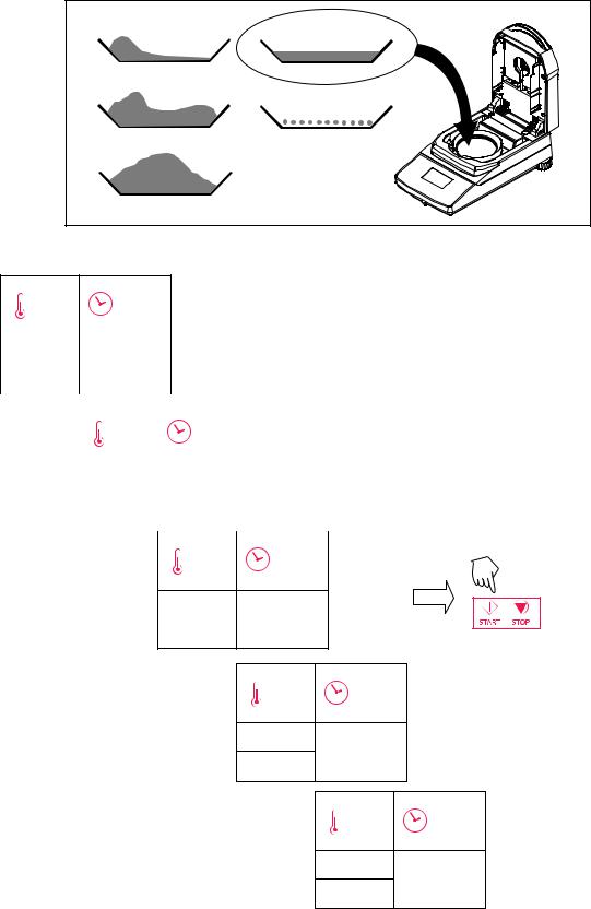
4.3 Sample Preparation
Please keep in mind the importance of preparing your sample, the distribution of the sample on the weighing pan, the type of sample and the temperature range. Remember, the greater the number of uniform samples tested, the greater the accuracy of the results. Careful sample preparation is important for best results. At a minimum, follow these steps.
Results of substances which form crusts (e.g. glucose syrup) or pasty substances (e.g. butter) can be considerably improved by mixing with quartz sand.
For pasty, fat containing and melting substances, use of a glass fiber filter is advantageous to increase the surface area of the sample.
The use of a glass fiber filter can be useful for temperature-sensitive and skin forming substances. In this case, the sample to be dried is covered by the filter and thus receives a ―new surface‖.
MB35 |
EN-15 |
|
|
|
|
4.3 Sample Preparation (Cont).
Clear the pan, press the Tare button.
Incorrect sample distribution |
Correct sample distribution |
Distribution |
Correct amount |
Piling |
Homogenously distributed |
Excessive amount |
|
4.4 Running the Test
130° |
05:00 |
|
|
|
|
Initial display. |
|
SAMPLE |
0.000g |
|
|||
|
|
|
|||
<.500G |
* |
|
|
|
|
|
|
|
|
|
|
|
|
|
|
Place sample on pan. |
|
|
|
|
|
||
|
|
|
|
||
|
130° |
|
05:00 |
(See above for correct sample distribution) |
|
|
|
|
|
|
|
|
CLOSE |
|
0.000g |
|
|
|
COVER |
|
* |
|
|
|
|
|
|
|
|
|
|
|
|
|
Start process. |
|
|
|
|
|
|
|
|
|
130° |
05:00 |
|
|
|
|
|
||
TEST
READY 1.300g
PRESS *
START
Sample during drying process.
130° |
05:00 |
130°C 29.60%
02:45 * 0.915G
Test end.
100° |
05:00 |
TEST
OVER... 29.60%
05:00 * 0.915G
EN-16 |
MB35 |
|
|
|
|
4.5 RS232 Command Table
Output Formats
Data output can be initiated in one of three ways:
1.By pressing the Print button;
2.Using the Print Interval feature;
3.Sending a print command (―P‖) from a computer.
RS232 Commands
All communication is accomplished using standard ASCII format. Only the characters shown in the following table are acknowledged by the Moisture Analyzer. Invalid command response "ES" error indicates the Moisture Analyzer has not recognized the command. Commands sent to the Moisture Analyzer must be terminated with a Line Feed or carriage return-line line feed (CRLF). Data output by the Moisture Analyzer is always terminated with a carriage return-line feed (CRLF).
|
RS232 COMMAND TABLE |
|
|
Command |
|
Character |
Description |
|
|
V |
Print SR Version |
|
|
ESC V |
Print S/N (unit ID) |
|
|
? |
Print current mode. |
TIME |
Print Current Time |
|
|
DATE |
Print Current Date |
|
|
P |
Print elapsed time and present reading |
|
|
RS232 Pin out
The following table illustrates the pin-out connections on the RS232 connector.
1 |
|
N/C |
2 |
<– |
Date Out (TXD) |
3 |
–> |
Date Out (RXD) |
|
|
|
4&6 |
|
Pins 4 and 6 are connected together. |
|
|
|
5 |
|
Ground |
|
|
|
7 |
–> |
Clear to send (CTS) |
8 |
<– |
Request to send (RTS) |
9 |
|
N/C |
|
|
|
MB35 |
EN-17 |
|
|
|
|
5. Care and Maintenance
In this section, you will learn how to keep your Moisture Analyzer in good condition and how to replace expendable parts.
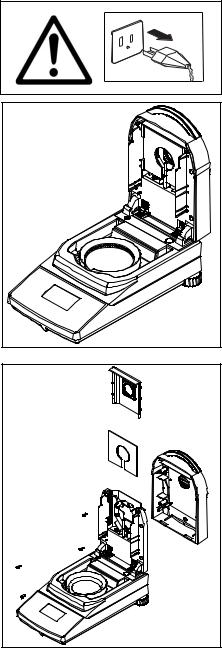
5.1 Cleaning Interior/Exterior Components
To continue to obtain precise measurements, it is advisable to clean the interior components at regular intervals. Please note the following instructions for cleaning your instrument.
Disconnect the instrument from the power supply before cleaning.
Cleaning Temperature Sensor and Protective Glass
Check the protective glass and the temperature sensor for debris which could impede the operation. If the glass appears dirty, clean the surface facing the compartment using a commercial glass cleaner. If the sensor is dirty, clean using a mild cleaning agent.
Removing Glass for Cleaning
If the inside of the glass is dirty, open the cover and remove the four cover screws as shown.
Remove the glass holder and glass from the cover and clean with a commercial glass cleaner on both sides.
Reassemble after cleaning.
EN-18 |
MB35 |
|
|
|
|
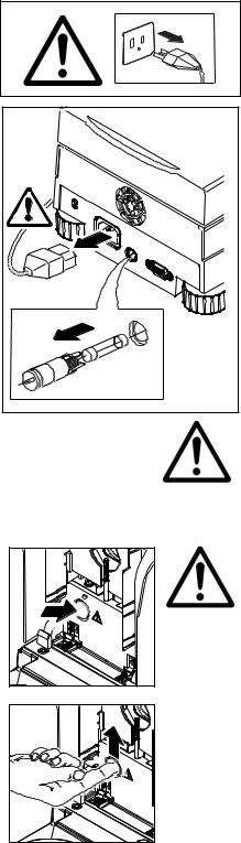
5.2 Replacing Power Line Fuse
If the instrument display fails to light after switching it on, check the power outlet first. If power is available, and the instrument fails to operate, the power fuse may be open (blown).
Disconnect the instrument from the power supply before cleaning.
Using a screwdriver, turn the fuse holder to the left (counterclockwise) and remove the fuse.
Check the condition of the fuse. Replace blown fuse by those of the same type with the same rated value (5 x 20 mm, T6.3H 250 V).
NOTE: If the fuse is good and power is available at the outlet, the cord or instrument may be defective. Try a new cord. If this does not work, the instrument should be sent back for servicing.
The use of a fuse of a different type or with a different value, or bridging or shunting the fuse is not allowed and can possibly cause a hazard to your safety and lead to instrument damage!
5.3 Resetting the dryer thermal overload device
NOTE: This procedure only applies to units that contain an access hole to the thermal overload protection device. See illustrations.
If the dryer has overheated and the thermal overload protection device has responded, it can be reset as follows:
Disconnect the unit from the power supply.
Lift the top cover straight up and remove the access hole cover from the access hole using a flat head screwdriver.
Reset the overload device with your finger.
Replace the access hole cover and reconnect unit to power supply.
MB35 EN-19
5.4 Accessories |
|
|
|
Description |
Ohaus Part No. |
|
|
Span Calibration Mass 20 g ASTM Class 1 Tolerance |
80780022 |
Security Locking Cable |
80850043 |
RS232 Interface Cable, 9 pin serial extension - PC to MB45 |
80500525 |
RS232 Interface Cable, MB35 to printer (25 pin) SF42 |
80500571 |
Data Printer |
SF42 |
Sample Pans 90mm diameter |
80850086 |
Glass Fiber Pads |
80850087 |
Pan, Re-usable - 90mm (set of three) |
80850088 |
In-use Cover |
80850085 |
Temperature Calibration Kit |
11113857 |
Pan Handler |
11113873 |
|
|
5.5 Specifications
Model MB35 |
|
|
|
|
|
Capacity |
|
35g |
|
|
|
Readability |
|
0.002g, 0.02% |
|
|
|
Temp. Settings |
|
50°C to 160°C (5°increments) |
|
|
|
Drying Programs |
|
Standard |
|
|
|
Switch-off Criteria |
|
Timed, Auto |
|
|
|
Heat Source |
|
Halogen |
|
|
|
Calibration |
|
External calibration mass-20g |
|
|
|
Dimensions (DxWxH) (cm) |
|
35.5 x 19 x 15.2 |
|
|
|
Pan Size |
|
90 mm. diameter |
|
|
|
Weight (kg) |
|
4.5 |
|
|
|
Shipping Weight (kg) |
|
6.4 |
|
|
|
|
|
|
Admissible ambient conditions |
|
|
|
|
|
Indoor use only |
|
|
Altitude: |
Up to 2000m |
|
Temperature range: |
5 ºC to 40 ºC |
|
Atmospheric humidity: |
Maximum relative humidity 80% for temperatures up to 31 °C |
|
|
decreasing linearly to 50% relative humidity at 40 °C. |
|
Warm-up time: |
At least 60 minutes after connecting the instrument to the |
|
|
power supply; when switched on from standby-mode, the |
|
|
instrument is ready for operation immediately. |
|
Voltage fluctuations: |
Mains supply voltage fluctuations up to –15% +10% of the |
|
|
nominal range |
|
Over voltage category: |
II |
|
Pollution degree: |
2 |
|
Power load: |
Max. 450 W during drying process |
|
Current consumption: |
4 A or 2 A, according to the heating element |
|
Power supply voltage: |
100 V – 120 V or 200 V – 240 V, 50/60 Hz |
|
|
(the voltage is given by the heating element) |
|
Power line fuse: |
1 piece, 5 x 20 mm, T6,3 H 250 V |
|
|
|
|
 Loading...