


AC Relay Option Kit P/N 80500720
DC Relay Option Kit P/N 80500727
Instruction Manual
Paquete opcional de relé de corriente alterna N/P 80500720 Paquete opcional de relé de corriente alterna N/P 80500727 Manual de instrucciones
Kit d'option du relais CA, réf. 80500720
Kit d'option du relais CC, réf. 80500727
Manuel d’instructions
Wechselstromrelais-Optionssatz, Teilenr. 80500720
Gleichstromrelais-Optionssatz, Teilenr. 80500727
Bedienungsanleitung
Kit opzionale relé di alimentazione CA, N/P 80500720 Kit opzionale relé di alimentazione CC, N/P 80500727 Manuale di istruzioni

Relay Option Kit |
EN-1 |
1. INTRODUCTION
AC Relay Kit 80500720 and DC Relay Kit 80500727 are intended for use with the Ohaus 5000 and 7000 Series Indicators. The AC relay kit is used to control up to three external AC circuits. The DC relay kit is used to control up to three external DC circuits. Each solid-state relay output is equivalent to a single pole, single throw switch (SPST). Each relay circuit is protected by a replaceable fuse.
Applications include: driving external Over/Accept/Under displays, motor controls for semi-automatic filling systems, sorting systems, interfacing to industrial PLC systems, etc. The Relay outputs can also be used as slave relays to drive higher power relays in larger systems.
Please read this manual completely before installation and operation.
CAUTION: READ ALL SAFETY WARNINGS BEFORE INSTALLING, MAKING CONNECTIONS, OR SERVICING THE RELAY OPTION. FAILURE TO COMPLY WITH THESE WARNINGS COULD RESULT IN PERSONAL INJURY AND/OR PROPERTY DAMAGE. RETAIN ALL INSTRUCTIONS FOR FUTURE REFERENCE.
1.1 Kit Contents
80500720 |
|
|
|
|
|
|
|
T51P, T71P parts |
T51XW, T71XW parts |
||
Common Parts |
(bag marked "T--P") |
(bag marked "T--XW") |
|||
• |
AC relay pc board |
• |
Terminal cover |
• |
Terminal cover |
• |
Instruction manual |
• |
Screws (6) |
• |
Screws (6) |
|
|
• |
Long cable |
• |
Long cable |
|
|
• |
Short cable |
• |
Short cable |
|
|
• |
Strain relief bushing |
• |
Cable tie (2) |
80500727 |
|
|
|
|
|
|
|
T51P, T71P parts |
T51XW, T71XW parts |
||
Common Parts |
(bag marked "T--P") |
(bag marked "T--XW") |
|||
• |
DC relay pc board |
• |
Terminal cover |
• |
Terminal cover |
• |
Instruction manual |
• |
Screws (6) |
• |
Screws (6) |
|
|
• |
Long cable |
• |
Long cable |
|
|
• |
Short cable |
• |
Short cable |
|
|
• |
Strain relief bushing |
• |
Cable tie (2) |

EN-2 |
Relay Option Kit |
2. INSTALLATION
2.1 Safety Precautions
For safe and dependable operation of this equipment, please comply with all safety precautions mentioned in this manual.
•Installation of these options should only be performed by qualified personnel.
•Disconnect all equipment from the mains power supply before beginning installation.
•If batteries are installed in the indicator’s battery compartment, remove them before beginning installation.
•If the rechargeable battery option is installed in the indicator, disconnect the battery from the charging pc board before beginning installation.
2.2 Relay Wiring Guidelines
WARNING: WHEN MAKING ANY LINE VOLTAGE CONNECTIONS TO THE AC RELAY OPTION, FOLLOW NATIONAL ELECTRICAL CODE (NEC) OR LOCAL AUTHORITY WIRING STANDARDS AND SAFETY PRACTICES.
IMPORTANT: WHEN CONNECTING ANY AC LINE SUPPLIED DEVICE TO THE RELAY OPTION, ENSURE THAT EACH EXTERNAL DEVICE UTILIZES A PROPERLY GROUNDED AC CONNECTION.
•For connections to nominal 120 VAC or 220-240 VAC systems, use only insulated wire sets rated to the local electrical code requirements.
•The wire sets used for connection to the relay option pc board must be part of a multi-conductor cable with a smooth, round outer insulating jacket.
•Do not run more than one cable through the strain relief bushing.
•Do not use the cable that connects to the relays to make other connections.
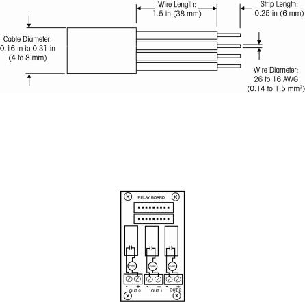
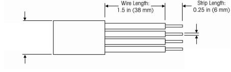
•The indicator’s strain relief bushing only permits cable diameters from 0.16 to 0.31 inch (4 to 8 mm).
•The terminal block on the relay pc board only permits wire sizes of 26 to 16 AWG (0.14 to 1.5 mm2). Strip the wire ends to 0.25 inch (6 mm).
Relay Option Kit |
EN-3 |
Figure 2.1 Wire Preparation
•The relay connections provide a switch closure only. AC or DC power must be supplied externally.
•Each relay output has a terminal block with two connections. See Figure 2.2, for the relay contact diagram.
-The AC relay pc board can only be used with AC circuits.
-The DC relay pc board can only be used with DC circuits.
Figure 2.2 Relay Contact Diagram.
•Connect each wire pair to the appropriate set of terminal block connections.
•For the DC relay pc board, make sure the polarity is correct.

EN-4 |
Relay Option Kit |
2.3 Relay Wiring Examples
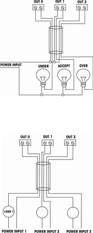
Figure 2.3. 4-wire relay connection with internal common line.
Figure 2.4. 6-wire relay connection with external common line.

Relay Option Kit |
EN-5 |
Figure 2.5. 6-wire relay connection with three separate power and load devices.

EN-6 |
Relay Option Kit |
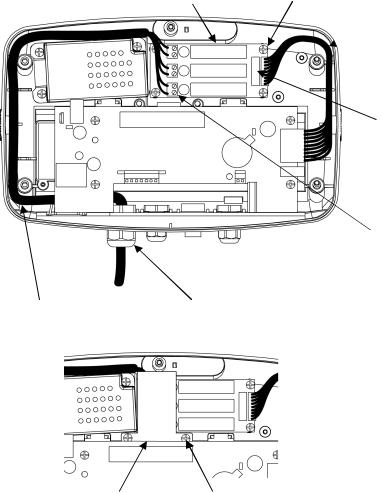
2.4 80500720 Installation in T51P and T71P
WARNING: ELECTRICAL SHOCK HAZARDS EXIST WITHIN THE HOUSING. THE HOUSING SHOULD ONLY BE OPENED BY AUTHORIZED AND QUALIFIED PERSONNEL. REMOVE ALL POWER CONNECTIONS TO THE UNIT BEFORE OPENING. IF THE UNIT CONTAINS AN OPTIONAL RELAY CONTROL BOARD, ADDITIONAL AC OR DC POWER CONNECTIONS MAY STILL EXIST WITHIN THE HOUSING.
Refer to Figure 2.6 when performing these steps.
1.Remove the four screws from the corners of the rear housing.
2.Pull the front housing forward.
3.Remove the plastic hole cover located next to the power connection from the rear housing.
3.Install the strain relief bushing in the exposed hole next to the power connection.
4.Attach the relay pc board to the rear housing using the four self tapping screws supplied.
5.Connect the long cable to one of the 9 pin connectors on the relay pc board and connector J8 on the main pc board.
Note: If an optional RS232 or RS485/422 pc board is already installed, do not use the long cable. Connect the short cable between the relay pc board and the optional RS232 or RS485/422 pc board instead.
6.Feed the cable from the external device through the new strain relief bushing and under the right side of the main pc board.
7.Attach the wires of the cable to the terminal blocks on the relay pc board.
8.Position the cable in the slots along the right side of the rear housing.
9.Pull the excess cable through the strain relief bushing and tighten the external nut on the bushing.
10.Install the terminal cover over the terminal block using the two self tapping screws supplied.
11.Close the housing and reinstall the four screws.
Relay Option Kit |
EN-7 |
Relay pc board |
Screws (4) |
|
Long |
|
cable |
9 pin connectors
 Connector
J8
Terminal
blocks
Cable from external device |
Strain relief bushing |
Terminal cover Screws (2)
Figure 2.6. T51P, T71P

EN-8 |
Relay Option Kit |
2.5 80500721 Installation in T51XW and T71XW
WARNING: ELECTRICAL SHOCK HAZARDS EXIST WITHIN THE HOUSING. THE HOUSING SHOULD ONLY BE OPENED BY AUTHORIZED AND QUALIFIED PERSONNEL. REMOVE ALL POWER CONNECTIONS TO THE UNIT BEFORE OPENING. IF THE UNIT CONTAINS AN OPTIONAL RELAY CONTROL BOARD, ADDITIONAL AC OR DC POWER CONNECTIONS MAY STILL EXIST WITHIN THE HOUSING.
Refer to Figure 2.7 when performing these steps.
1.Remove the hex bolts from the corners of the rear housing.
2.Pull the front housing forward.
3.Attach the relay pc board to the rear housing using the four machine screws supplied.
4.Connect the long cable to one of the 9 pin connectors on the relay pc board and connector J8 on the main pc board.
Note: If an optional RS232 or RS485/422 pc board is already installed, do not use the long cable. Connect the short cable between the relay pc board and the optional RS232 or RS485/422 pc board instead. Then skip to step 6.
5.Secure the long cable to the cable tie mount using the cable tie.
6.Feed the cable from the external device through the strain relief bushing furthest from the power cord.
7.Attach the wires of the cable to the terminal block on the relay pc board.
8.Pull the excess cable through the strain relief bushing and tighten the external nut on the bushing.
9.Attach a cable tie around the cable near the strain relief to prevent the cable from pulling out.
10.Install the terminal cover over the terminal block using the two machine screws supplied.
11.Close the housing and reinstall the four hex bolts.

|
Relay Option Kit |
|
EN-9 |
|
9 pin connectors |
Long cable |
Cable tie |
Screws (4) |
|
|
|
|
Relay pc |
|
Rear |
|
board |
|
housing |
|
Terminal |
|
Cable |
|
blocks |
|
mount |
Cable tie
Strain relief bushing
Cable from  external
device
 Front Connector housing
J8
Terminal |
Screws (2) |
cover |
|
Figure 2.7. T51XW, T71XW

EN-10 |
Relay Option Kit |
3. OPERATION
CAUTION: DO NOT OPERATE THE RELAY OPTION WITHOUT THE PROTECTIVE TERMINAL COVER IN PLACE.
IMPORTANT: REVIEW THE I/O MENU BEFORE USING THE RELAY OPTION BOARD TO CONTROL EXTERNAL DEVICES.
Refer to the instruction manual supplied with the indicator. Set up the relay controls as described in the I/O menu section of that manual.
The indicator software allows the relays to be programmed in a variety of ways. Optional set ups include: Normally open or normally closed simulation, on-off or onhold sequencing, simultaneous, break-before-make (BBM) or make-before-break (MBB) contact switching.
External devices can be coordinated to work with the indicator’s LED displays.
•Relay Out 0 corresponds to the Yellow LED.
•Relay Out 1 corresponds to the Green LED.
•Relay Out 2 corresponds to the Red LED.

Relay Option Kit |
EN-11 |
4. MAINTENANCE
4.1 Fuse Replacement
WARNING: ELECTRICAL SHOCK HAZARDS EXIST WITHIN THE HOUSING. THE HOUSING SHOULD ONLY BE OPENED BY AUTHORIZED AND QUALIFIED PERSONNEL. REMOVE ALL POWER CONNECTIONS TO THE UNIT BEFORE OPENING. IF THE UNIT CONTAINS AN OPTIONAL RELAY CONTROL BOARD, ADDITIONAL AC OR DC POWER CONNECTIONS MAY STILL EXIST WITHIN THE HOUSING.
1.Open the housing and remove the terminal cover
2.Replace the burned fuse with a 2.5 A / 250 V type TR5 radial fuse.
3.Reinstall the terminal cover and reassemble the housing.
4.2 Service Information
For Service assistance in the United States, call toll-free 1-800-526-0659 between 8:00 AM and 5:00 PM Eastern Standard Time. An Ohaus Product Service Specialist will be available to assist you. Outside the USA, please visit our website www.ohaus.com to locate the Ohaus office nearest you.

EN-12 |
Relay Option Kit |
5. TECHNICAL DATA
5.1 Specifications
Part Number |
80500720 |
80500727 |
Relay Type |
AC 1) |
DC |
Output Voltage Rating |
24-240 VAC |
5-60 VDC |
Current Rating |
1 A |
1 A |
Fuse Rating |
2.5 A / 250 V |
2.5 A / 250 V |
Off State Leakage |
5 mA max |
1 mA max |
Output Voltage Drop |
1.6 VAC |
1.5 VDC |
Isolation |
4000 V Optical |
4000 V Optical |
Load Type |
Resistive or Inductive 2) |
Resistive or Inductive 2) |
Fuse Type and Rating |
Type TR5 2.5 A 250V |
Type TR5 2.5 A 250V |
Notes:
1) AC relays are zero crossing turn-on, solid state type.

Paquete opcional de relé |
ES-1 |
1. INTRODUCCIÓN
Los paquetes de relé de corriente alterna 80500720 y 80500727 están diseñados para usarse con los indicadores Ohaus serie 5000 y 7000. Estos paquetes de relé de corriente alterna se usan para controlar hasta tres circuitos de corriente alterna externos. Los paquetes de relé de corriente continua se usan para controlar hasta tres circuitos de corriente continua externos. Cada salida de relé de estado sólido equivale a un interruptor simple (SPST). Cada circuito de relé está protegido por un fusible reemplazable.
Las aplicaciones incluyen: control de pantallas externas para pesos Por arriba, Aceptar y Por debajo, controles para sistemas de llenado semiautomático, sistemas de separación, interfaz con sistemas PLC industriales y otras. Las salidas de relé también pueden usarse como relés esclavos para controlar relés de mayor potencia en sistemas más grandes.
Lea completamente este manual antes de instalar y trabajar con su báscula.
PRECAUCIÓN: LEA TODAS LAS ADVERTENCIAS DE SEGURIDAD ANTES DE INSTALAR, HACER CONEXIONES O DAR SERVICIO A LA OPCIÓN DE RELÉ. LA FALTA DE CUMPLIMIENTO DE ESTAS ADVERTENCIAS PODRÍA RESULTAR EN LESIONES PERSONALES Y/O DAÑOS A LA PROPIEDAD.
CONSERVE TODAS LAS INSTRUCCIONES PARA REFERENCIA FUTURA.
1.1 Contenido del paquete
80500720 |
|
|
|
|
|
Partes comunes |
Partes T51P, T71P |
Partes T51XW, T71XW |
|||
|
|
(bolsa marcada "T--P") |
(bolsa marcada "T--XW") |
||
• |
Tarjeta de PC de |
• |
Tapa de terminales |
• |
Tapa de terminales |
|
relé de CA |
• |
Tornillos de fijación (6) |
• |
Tornillos de fijación (6) |
• |
Manual de |
• |
Câble largo |
• |
Câble largo |
|
instrucciones |
• |
Câble corto |
• |
Câble corto |
|
|
• |
Manguito de alivio de |
• |
Cintas para cable (2) |
|
|
|
tensión |
|
|

|
ES-2 |
|
|
Paquete opcional de relé |
|||
|
80500727 |
|
|
|
|
|
|
|
Partes comunes |
Partes T51P, T71P |
Partes T51XW, T71XW |
||||
|
|
|
(bolsa marcada "T--P") |
(bolsa marcada "T--XW") |
|||
|
• |
Tarjeta de PC de |
• |
Tapa de terminales |
• |
Tapa de terminales |
|
|
|
relé de CC |
• |
Tornillos de fijación (6) |
• |
Tornillos de fijación (6) |
|
|
• |
Manual de |
• |
Câble largo |
• |
Câble largo |
|
|
|
instrucciones |
• |
Câble corto |
• |
Câble corto |
|
|
|
|
• |
Manguito de alivio de |
• |
Cintas para cable (2) |
|
|
|
|
|
tensión |
|
|
|
2. INSTALACIÓN
2.1 Precauciones de seguridad
Para una operación segura y confiable de este equipo, siga todas las precauciones de seguridad mencionadas en este manual.
•La instalación de estas opciones sólo debe hacerse mediante personal calificado.
•Desconecte todo el equipo de la alimentación eléctrica principal antes de comenzar la instalación.
•Si hay baterías instaladas en el compartimiento de baterías del indicador, retírelas antes de comenzar la instalación.
•Si está instalada la opción de baterías recargables en el indicador, desconecte las baterías de la tarjeta de PC de carga antes de comenzar la instalación.
2.2 Recomendaciones de cableado del relé
ADVERTENCIA: CUANDO HAGA CUALESQUIER CONEXIONES DE
VOLTAJE DE LA LÍNEA CON LA OPCIÓN DE RELÉ DE CORRIENTE
ALTERNA, SIGA LAS NORMAS DE CABLEADO Y PRÁCTICAS DE
SEGURIDAD DEL CÓDIGO ELÉCTRICO NACIONAL (NEC) O DE SU
ENTIDAD LOCAL.
IMPORTANTE: CUANDO CONECTE ALGÚN DISPOSITIVO ALIMENTADO CON LA LÍNEA DE CORRIENTE ALTERNA A LA OPCIÓN DE RELÉ, ASEGÚRESE DE QUE CADA DISPOSITIVO EXTERNO UTILICE UNA CONEXIÓN DE CORRIENTE ALTERNA CONECTADA A TIERRA CORRECTAMENTE.
Paquete opcional de relé |
ES-3 |
•Para conexiones a los sistemas nominales de 120 VCA o 220-240 VCA, use solamente grupos de cables aislados clasificados para los requerimientos del código eléctrico local.
•Los grupos de cables usados para conectar la tarjeta de PC de opción de relé deben ser parte de un cable multiconductor que tenga un forro aislante externo liso y redondeado.
•No instale más de un cable a través del manguito de alivio de tensión.
•No use el cable que se conecta con los relés para hacer otras conexiones.
•El manguito de alivio de tensión del indicador sólo permite diámetros de cable de 0.16 a 0.31 pulgadas (4 a 8 mm).
•El bloque de terminales en la tarjeta de PC de relé sólo permite calibres de cable 26 a 16 AWG (0.14 a 1.5 mm2). Descubra los extremos de los cables 0.25 pulgadas(6 mm).
|
|
Longitud |
Longitud del hilo: |
||
1.5 pulgadas |
|
descubierta: |
(38 mm) |
|
0.25 pulgadas |
|
|
(6 mm) |
Diámetro del cable: 0.16 pulgadas a 0.312 pulgadas
(4 a 8 mm)
Diámetro del hilo: 26 a 16 AWG (0.14 a 1.5 mm²)
Figura 2.1 Preparación del cable
•Las conexiones del relé sólo proporcionan un cierre del interruptor. Se debe suministrar energía de corriente alterna o de corriente continua en forma externa.
•Cada salida de relé tiene un bloque de terminales con dos conexiones. La Figura 2.2 contiene el diagrama de contacto del relé.
-La tarjeta de PC de relé de CA sólo puede usarse con circuitos de CA.
-La tarjeta de PC de relé de CC sólo puede usarse con circuitos de CC.

ES-4 |
|
Paquete opcional de relé |
|
|
|
|
TARJETA DE RELÉ |
FUSIBLE FUSIBLE FUSIBLE
SAL 0 |
|
|
SAL 2 |
|
SAL 1 |
||
|
|
|
|
Figura 2.2 Diagrama de contacto del relé.
•Conecte cada par de cables en el grupo correspondiente de conexiones del bloque de terminales.
•Para la tarjeta de PC del relé de CC, asegúrese de que la polaridad sea correcta.
2.3 Ejemplos de cableado de relé
SAL0 |
SAL 1 |
SAL 2 |
ALIMENTACIÓN DE ENERGÍA |
|
|
|
|
|
|
|
|
POR DEBAJO |
|
|
|
|||
|
|
ACEPTAR |
|
POR ARRIBA |
|||
|
|||||||
Figura 2.3. Conexión de relé de 4 hilos con línea común interna.
Paquete opcional de relé |
|
|
ES-5 |
|
|
|
|
|
|
|
SAL0 |
SAL 1 |
SAL 2 |
|
|
|
|
|
|
|
POR |
ALIMENTACIÓN DE ENERGÍA |
|
|
|
|
||
|
|
|
ACEPTAR |
|
ARRIBA |
|
|
POR DEBAJO |
|
|
|||
|
|
|
|
|||
|
|
|
|
|||
|
|
|
|
|
|
|
Figura 2.4. Conexión de relé de 6 hilos con línea común externa.
SAL0 |
SAL 1 |
SAL 2 |
CARGA |
CARGA |
CARGA |
1 |
2 |
3 |
ALIMENTACIÓN |
|
ALIMENTACIÓN |
|
ALIMENTACIÓN |
DE ENERGÍA 1 |
|
DE ENERGÍA 2 |
|
DE ENERGÍA 3 |
|
|
|
|
|
Figura 2.5. Conexión de relé de 6 hilos con tres dispositivos de energía y carga separados.

ES-6 |
Paquete opcional de relé |
2.4 Instalación del 80500720 en T51P y T71P
ADVERTENCIA: EXISTE EL RIESGO DE DESCARGA ELÉCTRICA DENTRO DE LA CAJA LA CAJA DEBE SER ABIERTA SOLAMENTE POR PERSONAL AUTORIZADO Y CALIFICADO. DESCONECTE TODAS LAS CONEXIONES DE ENERGÍA HACIA LA UNIDAD ANTES DE ABRIRLA. SI LA UNIDAD CONTIENE UNA TARJETA DE CONTROL DE RELÉ OPCIONAL, ES POSIBLE QUE EXISTAN CONEXIONES DE ENERGÍA ADICIONALES DE CORRIENTE ALTERNA O DE CORRIENTE CONTINUA EN EL INTERIOR DE LA CAJA.
Consulte la Figura 2.6 cuando realice estos pasos.
1.Retire los cuatro tornillos de las esquinas de la caja posterior.
2.Tire de la caja anterior hacia adelante.
3.Retire la tapa de plástico del orificio ubicada junto a la conexión de energía de la caja posterior.
3.Instale el manguito de alivio de tensión en el orificio expuesto junto a la conexión de energía.
4.Fije la tarjeta de PC de relé en la caja posterior mediante los cuatro tornillos autorroscantes incluidos.
5.Conecte el cable largo en uno de los 9 conectores de patilla en la tarjeta de PC de relé y en el conector J8 en la tarjeta de PC principal.
Nota: Si ya está instalada una tarjeta de PC RS232 o RS485/422 opcional, no use el cable largo. En su lugar, conecte el cable corto entre la tarjeta de PC de relé y la tarjeta de PC RS232 o RS485/422 opcional.
6.Alimente el cable desde el dispositivo externo a través de un nuevo manguito de alivio de tensión y debajo del lado derecho de la tarjeta de PC principal.
7.Fije los hilos del cable en los bloques de terminales en la tarjeta de PC de relé.
8.Coloque el cable en las ranuras junto al lado derecho de la caja posterior.
9.Jale el exceso de cable a través del manguito de alivio de tensión y apriete la tuerca externa en el manguito.
10.Instale la tapa de terminales sobre el bloque de terminales mediante los dos tornillos autorroscantes incluidos.
11.Cierre la caja y reinstale los cuatro tornillos.
 Loading...