


Model CD-11 Indicator
Instruction Manual
Indicador Modelo CD-11 Manual de instrucciones
Indicateur modèle CD-11 Manuel d’instruction
 *
*
Ohaus Corporation, 19A Chapin Road, P.O. Box 2033 Pine Brook, New Jersey, 07058, USA
Declaration of Conformity We, Ohaus Corporation, declare under our sole responsibility that the balance models listed below marked with “CE” - are in conformity with the directives and standards mentioned.
Declaración de Conformidad Nosotros, Ohaus Corporation, declaramos bajo responsabilidad exclusiva que los modelos de balanzas indicados a continuación - con el distintivo ,CE’ - están conformes con las directivas y normas citadas.
Déclaration de conformité Nous, Ohaus Corporation, déclarons sous notre seule responsabilité, que les types de balance ci-dessous cité - munis de la mention «CE» - sont conformes aux directives et aux normes mentionnées ci-après.
Model/Modelo/Modèle CD-11
EC Marking: |
EC Directive |
Applicable Standards |
Marcado EC |
Directive EC |
Normas aplicables |
Marquage CE |
Directive CE |
Normes applicable |
|
|
|
|
73/23/EEC |
EN60950-1:2001 |
|
Low Voltage |
|
|
Baja tensión |
|
|
Basse tension |
|
|
|
|
|
89/336/EEC |
EN61326-1: 1997 + A1:98 + A2:01 +A3:03 |
|
Electromagnetic compatibility |
|
|
Compatibilidad electromagnética |
|
|
Compatibilité électromagnétique |
|
|
|
|
For non-automatic weighing instruments used in an Article 1, 2.(a) application, additional metrological marking according to Annex IV of Council directive 90/384/EEC must be attached to the instrument
Para instrumentos de pesaje no automático usados en una aplicación descrita en el Artículo 1, 2.(a), se debe colocar sobre el instrumento una marcación metrológica adicional de acuerdo con el Anexo IV de la Directriz del Consejo 90/384/EEC.
Pour les instruments de pesage non-automatiques utilisés dans une application Article 1, 2.(a), un repérage métrologique additionnel conforme à l’Annexe IV de la Directive 90/384/EEC du Conseil doit être présent sur l’instrument.
M
year |
90/384/EEC |
EN45501:1992 1) 2) |
Non Automatic Weighing Instruments |
|
|
|
|
|
|
Para balanzas no automátäcas |
|
0103 |
Balances à fonctionnement non automatique |
|
|
|
|
|
|
|
1) Applies only to certified non-automatic weighing instruments
Aplicable solamente a instrumentos de pesaje aprobados de funcionamiento no automático S’applique uniquement aux instruments de pesage à fonctionnement non automatique approuvés
2)Valid only for CW-11 terminals in connection with approved load cells
Valable seulement pour les indicateurs CW-11 connectés à des cellules de pesée approuvées. Válido solamente para terminales CW-11 en conexión con células de carga aprobadas
Date: May, 5, 2006
Ted Xia
President
Ohaus Corporation
Pine Brook, NJ USA
Urs Muller
General Manager
Ohaus Europe
Greifensee, Switzerland

Important notice for verified weighing instruments
Weighing Instruments verified at the place of manufacture bear one of the preceding mark on the packing label and the green ‘M’ (metrology) sticker on the descriptive plate. They may be put into service immediately.
Weighing Instruments to be verified in two stages have no green ‘M’ (metrology) on the descriptive plate and bear one of the preceding identification mark on the packing label. The second stage of the initial verification must be carried out by the approved service organization of the authorized representative within the EC or by the national weight & measures (W+M) authorities.
The first stage of the initial verification has been carried out at the manufacturers work. It comprises all tests according to the adopted European standard EN 45501:1992, paragraph 8.2.2.
If national regulations limit the validity period of the verification, the user of the weighing instrument must strictly observe the re-verification period and inform
the respective W+M authorities.
Notificación importante para instrumentos de pesaje verificados
Los instrumentos de pesaje verificados en el sitio de fabricación llevan una de las marcas precedentes en el rótulo del empaque y la etiqueta de la ‘M’ verde (metrología) en la placa descriptiva. Estos instrumentos se pueden poner en funcionamiento inmediatamente.
Los instrumentos de pesaje a ser verificados en dos etapas no tienen ninguna ‘M’ verde (metrología) en la placa descriptiva, y presentan una de las marcas de identificación precedentes sobre el rótulo del empaque. La segunda etapa de la verificación inicial debe ser llevada a cabo por la organización de servicio aprobada del representante autorizado dentro de la CE o por las autoridades nacionales de pesos y medidas.
La primera etapa de la verificación inicial ha sido llevada a cabo en el sitio de fabricación. Ésta comprende todas las pruebas estipuladas por el estándar europeo adoptado: EN 45501:1992, párrafo 8.2.2.
Si las normas nacionales limitan el periodo de validez de la verificación, el usuario del instrumento de pesaje debe seguir estrictamente el periodo de re-verificación e informar a las correspondientes autoridades de pesos y medidas.
Avis important pour les instruments de pesage vérifiés
Les instruments de pesage vérifiés sur le site de fabrication portent l’une des marques précédentes sur l’étiquette de l’emballage avec un autocollant M (pour Métrologie) en vert sur la plaque descriptive. Ces instruments peuvent être immédiatement mis en service.
Les instruments de pesage à vérifier en deux étapes ne portent pas d’autocollant M (pour Métrologie) en vert sur la plaque descriptive et portent l’une des marques d’identification précédentes sur l’étiquette de l’emballage. La deuxième étape de la vérification initiale doit être exécutée par l’organisation de service homologuée du représentant agréé au sein de la CE ou par les autorités nationales de poids et mesures.
La première étape de la vérification initiale a été exécutée sur le site du fabricant. Elle se compose des tests requis par la norme européenne EN45501:1992, paragraphe 8.2.2.
Si des règlements nationaux limitent la durée de validité de la vérification, il incombe à l’utilisateur dudit instrument de pesage de respecter strictement la période de re-vérification et d’informer les autorités de poids et mesures respectives.
Disposal
In conformance with the European Directive 2002/96 EC on Waste Electrical and Electronic Equipment (WEEE) this device may not be disposed of in domestic waste. This also applies to countries outside the EU, per their specific requirements.
Please dispose of this product in accordance with local regulations at the collecting point specified for electrical and electronic equipment.
If you have any questions, please contact the responsible authority or the distributor from which you purchased this device.
Should this device be passed on to other parties (for private or professional use), the content of this regulation must also be related.
Thank you for your contribution to environmental protection.
Eliminación de residuos
De conformidad con las exigencias de la directiva europea 2002/96 CE sobre residuos de aparatos eléctricos y electrónicos (RAEE), este equipo no puede eliminarse como basura doméstica. Esta prohibición es asimismo válida para los países que no pertenecen a la UE cuyas normativas nacionales en vigor así lo reflejan.
Elimine este producto, según las disposiciones locales, mediante el sistema de recogida selectiva de aparatos eléctricos y electrónicos.
Si tiene alguna pregunta al respecto, diríjase a las autoridades responsables o al distribuidor que le proporcionó el equipo.
Si transfiere este equipo (por ejemplo, para la continuación de su uso con fines privados, comerciales o industriales), deberá transferir con él esta disposición.
Muchas gracias por su contribución a la conservación medioambiental.
Elimination
En conformité avec les exigences de la directive européenne 2002/96 CE relative aux déchets d'équipements électriques et électroniques (DEEE), cet appareil ne doit pas être éliminé avec les déchets ménagers. Logiquement, ceci est aussi valable pour les pays en dehors de l'UE conformément aux règlementations nationales en vigueur.
Veuillez éliminer cet appareil conformément aux prescriptions locales dans un conteneur séparé pour appareils électriques et électroniques.
Pour toute question, adressez-vous aux autorités compétentes ou au revendeur chez qui vous avez acheté cet appareil.
En cas de remise de cet appareil (p. ex. pour une utilisation privée ou artisanale/industrielle), cette prescription doit être transmise en substance.
Merci pour votre contribution à la protection de l'environnement.
FCC Note
This equipment has been tested and found to comply with the limits for a Class A digital device, pursuant to Part 15 of the FCC Rules. These limits are designed to provide reasonable protection against harmful interference in a residential installation. This equipment generates, uses and can radiate radio frequency energy and, if not installed and used in accordance with the instructions, may cause harmful interference to radio communications. However, there is no guarantee that interference will not occur in a particular installation. If this equipment does cause harmful interference to radio or television reception, which can be determined by turning the equipment off and on, the user is encouraged to try to correct the interference by one or more of the following measures:
•Reorient or relocate the receiving antenna.
•Increase the separation between the equipment and receiver.
•Connect the equipment into an outlet on a circuit different from that to which the receiver is connected.
•Consult the dealer or an experienced radio/TV technician for help.
Industry Canada Note
This Class B digital apparatus complies with the Canadian ICES-003.
Cet appareil numérique de la classe B est conforme à la norme NMB-003 du Canada.
ISO 9001 Registration
In 1994, Ohaus Corporation, USA, was awarded a certificate of registration to ISO 9001 by Bureau Veritus Quality International (BVQI), confirming that the Ohaus quality management system is compliant with the ISO 9001 standard’s requirements. On May 15, 2003, Ohaus Corporation, USA, was re-registered to the ISO 9001:2000 standard.
Registro ISO 9001
En 1994, Bureau Veritus Quality International (BVQI) le otorgó a Ohaus Corporation, EE.UU., un certificado de registro ISO 9001 el cual confirma que el sistema administrativo de calidad de Ohaus cumple con los requerimientos del estándar ISO 9001. En mayo 15 del 2003, Ohaus Corporation, EE.UU., fue registrada nuevamente al estándar ISO 9001:2000.
Enregistrement ISO 9001
En 1994, le Bureau Veritus Quality International (BVQI) a octroyé la certification d’enregistrement ISO 9001 à Ohaus Corporation, ÉtatsUnis d’Amérique, confirmant que le système de gestion de la qualité Ohaus était conforme aux conditions normalisées de l’ISO 9001. Le 15 mai 2003, Ohaus Corporation, États-Unis d’Amérique, a été ré-enregistrée à la norme ISO 9001:2000.

CD-11 Indicator EN-1
TABLE OF CONTENTS
OVERVIEW OF CONTROLS AND INDICATOR FUNCTIONS |
................................................................................................. 3 |
||
1. |
GETTING TO KNOW YOUR INDICATOR ..................................................................................................................... |
4 |
|
1.1 |
Introduction ....................................................................................................................................................... |
4 |
|
1.2 |
Features......... ..................................................................................................................................................... |
4 |
|
1.3 |
Safety precautions ................................................................................................................................................ |
4 |
|
2. |
INSTALLATION ...................................................................................................................................................... |
5 |
|
2.1 |
Unpacking and Checking ....................................................................................................................................... |
5 |
|
2.2 |
Selecting the Location ........................................................................................................................................... |
5 |
|
2.3 |
Connecting the Indicator to a Scale Base ................................................................................................................ |
5 |
|
2.4 |
Connecting the RS232 Interface .............................................................................................................................. |
7 |
|
2.5 |
Connecting Power ................................................................................................................................................. |
7 |
|
|
2.5.1 |
AC Adapter ................................................................................................................................................. |
7 |
|
2.5.2 |
Battery Installation ...................................................................................................................................... |
7 |
|
2.5.3 |
Switching on the Indicator ........................................................................................................................... |
8 |
2.6 |
Initial |
Setup ....................................................................................................................................................... |
8 |
|
2.6.1 |
Control Functions ........................................................................................................................................ |
8 |
|
2.6.2 |
Menu Structure ........................................................................................................................................... |
9 |
|
2.6.3 |
Load Parameters ....................................................................................................................................... |
10 |
|
2.6.4 |
Setup Menu .............................................................................................................................................. |
11 |
|
2.6.5 |
Readout Menu .......................................................................................................................................... |
13 |
|
2.6.6 |
Print menu ............................................................................................................................................... |
17 |
|
2.6.7 |
Lockout Menu ........................................................................................................................................... |
19 |
3. |
CALIBRATION AND SEALING ................................................................................................................................. |
21 |
|
3.1 |
Legal for Trade (LFT) Operation and LFT Sealing ................................................................................................... |
25 |
|
4. |
OPERATION ..................................................................................................................................................... |
26 |
|
4.1 |
Turning On Indicator ........................................................................................................................................... |
26 |
|
4.2 |
Turning Off Indicator ........................................................................................................................................... |
26 |
|
4.3 |
Zero Operation .................................................................................................................................................... |
26 |
|
4.4 |
Tare Operation .................................................................................................................................................... |
26 |
|
4.5 |
Gross/Net/Tare Recall Operation ........................................................................................................................... |
27 |
|
EN-2 |
CD-11 Indicator |
TABLE OF CONTENTS (Cont.)
4.6 |
Clear Tare Operation ........................................................................................................................................... |
27 |
|
4.7 |
Unit Switch Operation .......................................................................................................................................... |
27 |
|
4.8 |
Parts Counting Operation ..................................................................................................................................... |
28 |
|
4.9 |
Establishing the Average Piece Weight (APW) ....................................................................................................... |
28 |
|
4.10 Returning to a Weighing Mode ........................................................................................................................... |
29 |
||
4.11 Returning to a Preset APW ................................................................................................................................. |
29 |
||
4.12 Display Hold Modes .......................................................................................................................................... |
29 |
||
|
4.12.1 |
Manual Display Hold (dHMAn) ................................................................................................................. |
29 |
|
4.12.2 |
Semi-automatic Display Hold (dHSEM) ..................................................................................................... |
30 |
|
4.12.3 |
Automatic Display Hold (dHAuto) ............................................................................................................. |
31 |
4.13 RS232 Commands ............................................................................................................................................ |
31 |
||
4.14 Printing Data .................................................................................................................................................... |
32 |
||
5. |
CARE AND MAINTENANCE ................................................................................................................................... |
33 |
|
5.1 |
Troubleshooting .................................................................................................................................................. |
33 |
|
5.2 |
Error Codes List .................................................................................................................................................. |
35 |
|
5.3 |
Service Information ............................................................................................................................................. |
35 |
|
5.4 |
Replacement Parts .............................................................................................................................................. |
35 |
|
5.5 |
Accessories ..................................................................................................................................................... |
35 |
|
5.6 |
Technical Data ................................................................................................................................................... |
35 |
|
CD-11 Indicator |
EN-3 |
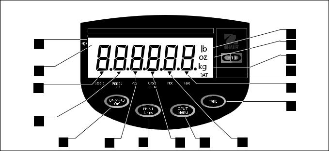
OVERVIEW OF CONTROLS AND INDICATOR FUNCTIONS
|
|
16 |
1 |
* |
15 |
|
||
|
|
14 |
2 |
|
13 |
3 |
|
12 |
|
|
11 |
4 |
|
|
5 |
6 |
7 |
8 |
9 |
10 |
No. |
Designation |
Function |
|
|
|
1 |
Display |
LCD display, indicates weight, modes and setup information. |
2 |
Center of Zero |
LCD indicator prompt, indicates center of zero when within +/- 0.25d. |
3 |
Stable |
LCD indicator prompt, indicates that the measured value has become stable. |
4 |
Display Hold |
LCD indicator prompt, indicates display hold is active. |
5 |
ON/ZERO/Off button |
Turns Indicator on or off. Secondary use, provides zero function. |
6 |
Pcs |
LCD indicator prompt, indicates parts counting function is active. |
7 |
PRINT/Units button |
Short press, prints data which is displayed on the Indicator. |
|
|
Long press, changes unit of measure or mode. |
|
|
When in menus, each press advances through the menus. |
|
|
When in submenus or establishing Average Piece Weights, each press |
|
|
toggles through settings. |
8 |
Gross Brutto |
LCD indicator prompt, indicates gross weight. |
9 |
G/N/T/Menu button |
Recalls Gross/Net/Tare. Long press allows entry into menus. |
|
|
When in menus, accepts the settings. |
|
|
when in parts counting mode, long press sets up Average Piece Weight. |
10 |
Net |
LCD indicator prompt indicates net weight. |
11 |
TARE button |
When pressed, enters tare value into memory. |
12 |
Tare |
LCD indicator prompt indicates tare weight. |
|
|
When establishing print interval, increments through the settings. |
13 |
BAT |
LCD indicator prompt, indicates low battery. |
14 |
kg |
LCD indicator, when lit, indicates weight in kilograms. |
|
g |
LCD indicator, when lit, indicates weight in grams. |
15 |
oz |
LCD indicator, when lit, indicates weight in ounces. |
16 |
lb |
LCD indicator, when lit, indicates weight in pounds. |
EN-4 |
CD-11 Indicator |
1. GETTING TO KNOW YOUR INDICATOR
1.1 Introduction
Thank you for deciding to purchase a CD-11 Indicator from Ohaus. The Ohaus CD-11 Indicator is a rugged, reliable, electronic weight indicator designed for easy operation.
Behind your instrument stands OHAUS, a leading manufacturer of precision Indicators, Scales and Balances. An Aftermarket Department with trained instrument technicians is dedicated to providing you with the fastest service possible in the event your instrument requires servicing. OHAUS also has a Customer Service Department to answer any inquiries regarding applications and accessories.
To ensure you make full use of the possibilities offered by your CD-11 Indicator, please read the manual completely before installation and operation.
1.2 Features
Major features include:
•6 digits, 7-segments, 25 mm high digits; backlit LCD display
•4 function membrane switch
•Supports up to four (4) 350 ohm analog load cells
•Up to 20,000d displayed resolution
•Flexible unit switching: lb/kg/oz/g
•Capacities from 5 to 20,000 lb/kg
•AC power adapter or 6 Alkaline "C" battery operation
•Power-saving Auto Shut-off timer
•Low battery warning
•Standard built-in RS-232 interface
•Parts Counting or Display Hold modes
•Available table, wall or tower mounting accessories
1.3Safety Precautions
Model CD-11 Indicator must not be operated in hazardous areas.
Before connecting the AC adapter, verify that the voltage printed on it corresponds to the local mains voltage. If this is not the case, please contact your local Ohaus dealer.
Model CD-11 Indicator may only be used in a dry environment.
CD-11 Indicator |
EN-5 |
2. INSTALLATION
2.1 Unpacking and Checking
Open the package and remove the instrument and the accessories. Check the completeness of the delivery. The following accessories are part of the standard equipment of your new Indicator.
Remove packing material from the instrument.
Check the instrument for transport damage. Immediately inform your Ohaus dealer if you have complaints or parts are missing. Your Indicator package should contain:
•Indicator CD-11
•AC Adapter
•Warranty card
•Capacity label
•Screw driver (for terminal connections)
•Instruction Manual
•Sealing Kit
•RS232 connector
Store all parts of the packaging. This packaging guarantees the best possible protection for the transport of your instrument.
2.2 Selecting the Location
The Indicator should be used in an environment which is free from corrosives, vibration, temperature or humidity extremes. These factors will affect displayed weight readings. Scale bases used with the Indicator should be located on a stable level surface and kept away from vibrating sources such as large machinery. Maximum accuracy will be achieved when the area is clean and vibration free.
2.3 Connecting the Indicator to a Scale Base
Turn the Indicator over and using a Phillips screw driver, remove the four screws which secure the rear cover. Two screws are under the battery cover.
Remove the rear cover.
Pass the load cell cable through the liquid tight connector on the left side of the housing.
Refer to the color code of the load cell cable and connect the wires to Terminal Strip J4. Tighten all screws securely.

EN-6 |
CD-11 Indicator |
2.3 Connecting the Indicator to a Scale Base (Cont.)
|
|
|
|
|
|
|
1 |
|
5 |
|
|
|
|
|
|
|
|
J5 |
|
|
|
|
|
|
|
|
|
|
3 |
|
|
|
|
|
|
|
DISPLAY |
J6 |
2 |
|
|
|
|
|
|
|
|
||
|
|
|
|
|
|
|
|
|
|
6 |
5 |
|
|
|
|
|
|
|
1 |
|
J3 |
|
|
|
|
|
|
|
4 |
|
|
|
|
|
|
|
|
|
|
9 |
1 |
|
|
|
|
|
|
J7 |
|
|
|
|
|
|
|
|
|
||
|
|
|
|
|
|
|
|
|
|
|
|
JUMP 1 |
|
|
|
1 |
|||
|
|
|
|
|
|
||||
|
|
JUMP 2 |
|
CAL |
|
|
|||
|
|
|
|
|
|
|
|
|
|
|
|
|
|
J4 |
|
|
|
|
|
|
1 |
2 |
3 |
4 |
5 |
6 |
7 |
|
|
|
+EXE +SEN +SIG CGND -SIG |
-SEN -EXE |
|
|
|||||
Printed Circuit Board Connector Locations.
J4 |
1 |
|
2 |
|
3 |
|
4 |
|
5 |
|
6 |
|
7 |
|
|
||||||||||||||
|
|
|
|
|
|
|
|
|
|
|
|
|
|
|
|
|
|
|
|
|
|
|
|
|
|
|
|
|
|
|
|
|
|
|
|
|
|
|
|
|
|
|
|
|
|
|
|
|
|
|
|
|
|
|
|
|
|
|
|
|
|
|
|
|
|
|
|
|
|
|
|
|
|
|
|
|
|
|
|
|
|
|
|
|
|
|
|
|
|
|
|
|
|
|
|
|
|
|
|
|
|
|
|
|
|
|
|
|
|
|
|
|
|
|
|
|
|
|
|
|
|
+EXE |
|
+SEN |
|
+SIG |
|
CGND |
|
-SIG |
|
-SEN |
|
-EXE |
|
||||||||||||||
Connector J4 Terminations.
For load cells without sense capability (4-wire), Jump 1 and Jump 2 must be shorted as shown in the illustration.
For load cells with sense capability (6-wire), Jump 1 and Jump 2 must be open.
JUMP 1


 JUMP 2


4-Wire |
6-Wire |
Jumper Connections. |
Jumper Connections. |
CD-11 Indicator |
EN-7 |
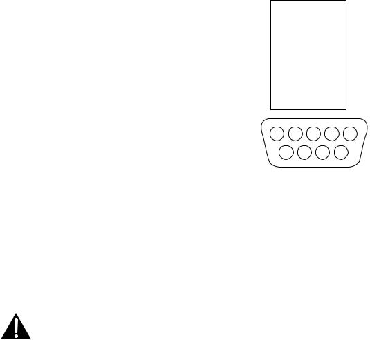
2.4 Connecting the RS232 Interface
CD-11 Indicators are equipped with a standard IBMTM compatible, bi-direc- tional RS232 interface for communication with printers and computers. When the Indicator is connected directly to a printer or a PC, displayed data can be recorded at any time by simply pressing the Print/Units button.
Connecting the Indicator to a computer enables you to operate several functions of the Indicator from the computer, as well as receive data such as displayed weight, weighing mode, stability status, etc.
Hardware
A 9-pin female “D” connector located on the left side of the indicator is provided for interfacing to other devices. Pin connections are shown in the adjacent illustration.
1N/C
2RXD
3TXD
4N/C
5GND
6N/C
7N/C
8N/C
9N/C
5 4 3 2 1
9 8 7 6
RS-232 Connector Pin Layout.
2.5 Connecting Power
The CD-11 Indicator may be operated using the AC Adapter supplied, or 6 Alkaline C-type batteries (not supplied).
2.5.1 AC Adapter
Connect the AC Adapter connector to the receptacle located at the right-hand side of the Indicator and plug the adapter into a convenient outlet.
NOTICE:
The socket/outlet must be installed near the equipment and shall be easily accessible.
2.5.2 Battery Installation
Open the battery cover on the bottom of the housing.
Insert 6 Alkaline C-type batteries into the two battery sleeves (3 in each sleeve) making sure the batteries are all facing in the same direction.
Place the batteries into the two slots in the housing. Orient the batteries so that the positive (+) ends are against the reeds and the negative (-) ends rest against the springs.
EN-8 |
CD-11 Indicator |
2.5.2 Battery Installation (Cont.)
NOTE: It is recommended that when the CD-11 is operated from batteries, the Auto-Off Timer feature be turned on to extend battery life.
2.5.3 Switching On the Indicator
Once the Indicator and Scale Base are connected and installed, follow the setup procedure outlined below.
Power On/Off
With the Indicator connected to an appropriate power supply, press the ON/ZERO Off button. The Indicator performs a self-test, displays the software revision momentarily and then goes to a weighing mode.
At this point, the Indicator is on and ready for initial setup.
Stabilization
Before initially using the Indicator, allow time for it to adjust to its new environment. Recommended warm up period is five (5) minutes.
2.6 Initial Setup
The CD-11 Indicator is equipped with menus which permit certain functions to be locked out (not changed) during operation. If locking out changes to the setup selections, access the CAL jumper located on the circuit board following the setup procedure. Once all setup procedures are completed, reassemble the Indicator. For first time setup, step through all menus and set the parameters as desired. As the last step, enter the CAL menu and calibrate the system.
The Indicator has five menus; CAL (Calibration), SEtuP (Setup), rEAd (Read) , Print (Printing) and LOCSW (Lockswitch) which are entered by pressing and holding the G/N/T/Menu button until MEnu is displayed, then releasing it. The display then switches to CAL.
To access the rest of the menus, the PRINT/Units button is repeatedly pressed until the desired menu is reached.
2.6.1 Control Functions
During setup, the following buttons are used.
PRINT/Units Button
Change between menus horizontally or change sub-menu parameters.
G/N/T/Menu Button
Press and hold to enter menu. Enters menu and steps through sub-menus vertically.
Tare Button
Change print interval settings.
CD-11 Indicator |
|
|
|
|
|
|
|
|
|
|
|
|
|
|
|
|
|
|
|
|
|
|
|
|
EN-9 |
|||||||
2.6.2 |
|
|
Menu Structure |
|
|
|
|
|
|
|
|
|
|
|
|
|
|
|
|
|
|
|
|
|
|
|||||||
The following table illustrates the menu structure in the CD-11 Indicator. |
|
|
|
|
|
|
|
|
|
|
||||||||||||||||||||||
|
|
|
|
|
|
|
|
|
|
|
|
|
|
|
|
|
|
|
|
|
|
|
|
|
|
|
|
|
|
|
|
|
|
|
|
|
|
|
|
|
|
|
|
|
|
|
MAIN MENU |
|
|
|
|
|
|
|
|
|
|
|
|
|
|||||
|
|
|
|
|
|
|
|
|
|
|
|
|
|
|
|
|
|
|
|
|
|
|
|
|
|
|
|
|
|
|
|
|
|
|
|
|
|
|
|
|
|
|
|
|
|
|
|
|
|
|
|
|
|
|
|
|
|
|
|
|
|
|
|
|
|
CAL |
|
|
|
|
|
SEt uP |
|
|
|
rEAd |
|
|
|
|
|
|
|
|
LOCSW |
|
|
Quit |
||||||||||
|
|
|
|
|
|
|
|
|
|
|
|
|
|
|
|
|
|
|
|
|
|
|
|
|
|
|
|
|
|
|
(Exit to |
|
|
|
|
|
CALIBRATION |
|
|
|
|
|
|
|
|
|
|
* Reset rEAd menu to |
|
|
* Reset Print menu to |
|
|
|
|
weigh mode) |
|||||||||
|
|
|
|
|
|
Legal for Trade |
|
|
|
|
|
|
Lock SEtUP menu |
|||||||||||||||||||
|
|
|
|
|
|
|
|
|||||||||||||||||||||||||
|
|
|
|
|
|
|
|
|
|
|
|
factory defaults |
|
|
Factory defaults |
|
||||||||||||||||
|
|
|
|
|
|
|
|
|
LFtOFF, LFtOn, LFtCan |
|
|
|
|
|
|
LStOFF, LST On |
||||||||||||||||
|
|
|
|
SPAN Y |
|
|
|
|
|
rESEtn (no), rESEtY (yes) |
|
|
rESEtn (no), rESEtY (yes) |
|
||||||||||||||||||
|
|
|
|
|
|
Zero (Range) |
|
|
|
|
|
|
* Lock rEAd menu |
|||||||||||||||||||
|
|
|
|
LIN Y |
|
|
|
|
|
* Averaging Level |
|
|
* Baud Rate |
|
||||||||||||||||||
|
|
|
|
|
|
|
|
|
|
|
|
|||||||||||||||||||||
|
|
|
|
|
|
|
|
|
|
|
|
|||||||||||||||||||||
|
|
|
|
|
0 2 (2%), |
|
|
|
|
|
|
|
|
|
LrdOFF, Lrd On |
|||||||||||||||||
|
|
|
|
|
|
|
|
|
|
|
|
|
|
AL LO, AL HI |
|
|
bd1200, bd2400, bd4800, |
|
||||||||||||||
|
|
|
|
|
|
|
|
0 18 (18%), |
|
|
|
|
|
|
|
|
|
|
|
|
|
|||||||||||
|
|
|
|
GEO (Value) |
|
|
|
|
|
|
|
|
|
|
|
|
bd9600, bd19,200 |
|
* Lock Print menu |
|||||||||||||
|
|
|
|
|
0 100 (100%) |
|
|
|
|
|
* Stability Level |
|
|
|
||||||||||||||||||
|
|
|
|
|
|
|
|
|
|
|
||||||||||||||||||||||
|
|
|
|
GEO 0...gEO 12... |
|
|
|
|
|
|
|
|
|
|
|
|
|
|||||||||||||||
|
|
|
|
|
|
|
|
|
|
|
|
|
|
|
|
|
|
|
|
|
LPtOFF, |
LPtOn |
||||||||||
|
|
|
|
GEO 31 |
|
|
Calibration |
Unit |
|
|
|
StAb0.5 (0.5d), |
|
|
*Parity |
|
|
|
|
|
|
|||||||||||
|
|
|
|
|
|
|
|
|
|
|
|
|
||||||||||||||||||||
|
|
|
|
|
|
|
|
|
|
|
|
StAb1 (1d), StAb3 (3d) |
|
|
PAr nO (none), |
|
Lock CAL menu |
|||||||||||||||
|
|
|
|
|
|
|
|
|
CAL Un kg, |
|
|
|
|
|
|
|||||||||||||||||
|
|
|
|
|
|
|
|
|
|
|
|
|
||||||||||||||||||||
|
|
|
|
|
|
|
|
|
|
|
|
|
|
|
|
|
|
PAr Odd (odd), |
|
|||||||||||||
|
|
|
|
Save Settings |
|
|
CAL Un lb |
|
|
|
|
|
|
*Unit of Measure |
|
|
|
LCLOFF, LCL On |
||||||||||||||
|
|
|
|
|
|
|
|
|
|
|
|
|
|
PAr E (even) |
|
|||||||||||||||||
|
|
|
|
|
|
|
|
|
|
|
|
|
|
|
|
|
|
|
|
|
|
|||||||||||
|
|
|
|
SAVE |
|
|
Full Scale |
|
|
|
|
|
|
Un OFF g, Un On g, |
|
|
|
|
|
|
|
* Save Settings |
||||||||||
|
|
|
|
|
|
|
|
|
|
|
|
|
|
|
Un OFF lb, Un On lb, |
|
|
*Data Length |
|
|||||||||||||
|
|
|
|
|
|
|
|
|
|
|
|
|
|
|
|
|
||||||||||||||||
|
|
|
|
|
|
|
|
|
capacity |
|
|
|
|
|
|
|
|
|
SAVE |
|
|
|
||||||||||
|
|
|
|
|
|
|
|
|
|
|
|
|
|
|
Un OFF kg, Un On kg, |
|
|
dAtA 7, dAtA 8 |
|
|
|
|
||||||||||
|
|
|
|
|
|
|
|
|
F 5, to....... F20000 |
|
|
|
|
|
|
|
|
|
|
|
||||||||||||
|
|
|
|
|
|
|
|
|
|
|
|
Un OFF oz, Un On oz, |
|
|
|
|
|
|
|
|
|
|
|
|
||||||||
|
|
|
|
|
|
|
|
|
|
|
|
|
|
|
|
|
|
|
|
|
|
|
|
|
|
|
|
|
||||
|
|
|
|
|
|
|
|
|
Graduation Size |
|
|
|
|
|
|
|
|
|
*Stop Bit |
|
|
|
|
|
|
|||||||
|
|
|
|
|
|
|
|
|
|
|
|
|
|
|
|
|
|
|
|
|
|
|
|
|||||||||
|
|
|
|
|
|
|
|
|
|
|
|
|
|
|
|
|
|
StOP 1, StOP 2 |
|
|
|
|
|
|
||||||||
|
|
|
|
|
|
|
|
|
gd0.001, to ....gd 20 |
|
|
|
Alternate Mode |
|
|
|
|
|
|
|
|
|||||||||||
|
|
|
|
|
|
|
|
|
|
|
|
|
|
|
|
|
|
|
|
|
|
|
|
|||||||||
|
|
|
|
|
|
|
|
|
|
|
|
|
|
|
|
|
ALtOFF, (none) |
|
|
Auto Print mode |
|
|
|
|
|
|
||||||
|
|
|
|
|
|
|
|
|
Calibration Point |
|
|
|
ALtPC (Parts counting), |
|
|
|
|
|
|
|
|
|||||||||||
|
|
|
|
|
|
|
|
|
|
|
|
|
|
AP OFF, APCont, AP Int, |
|
|
|
|
|
|
||||||||||||
|
|
|
|
|
|
|
|
|
CP 5, to....C20000 |
|
|
|
ALtdH (Display hold) |
|
|
|
|
|
|
|
|
|||||||||||
|
|
|
|
|
|
|
|
|
|
|
|
|
|
AP StbL |
|
|
|
|
|
|
||||||||||||
|
|
|
|
|
|
|
|
|
|
|
|
|
|
|
|
|
|
|
|
|
|
|
|
|
|
|
|
|
||||
|
|
|
|
|
|
|
|
|
|
|
|
|
|
|
|
|
|
|
|
|
|
|
|
|
|
|
|
|
|
|
|
|
|
|
|
|
|
|
|
|
|
Save Settings |
|
|
|
(If ALtdH is selected, set |
|
|
|
|
|
|
|
|
|
|
|
|
|||||||
|
|
|
|
|
|
|
|
|
|
|
|
|
|
If AP Int is selected, set |
|
|
|
|
|
|
||||||||||||
|
|
|
|
|
|
|
|
|
SAVE |
|
|
|
|
|
|
display hold type) |
|
|
|
|
|
|
|
|
||||||||
|
|
|
|
|
|
|
|
|
|
|
|
|
|
|
|
|
Auto print interval |
|
|
|
|
|
|
|||||||||
|
|
|
|
|
|
|
|
|
|
|
|
|
|
|
|
|
dHMAn (manual), |
|
|
|
|
|
|
|
|
|||||||
|
|
|
|
|
|
|
|
|
|
|
|
|
|
|
|
|
|
|
Int 0001 to 3600 |
|
|
|
|
|
|
|||||||
|
|
|
|
|
|
|
|
|
|
|
|
|
|
|
|
|
dHSEM (semi-automatic), |
|
|
|
|
|
|
|
|
|||||||
|
|
|
|
|
|
|
|
|
|
|
|
|
|
|
|
|
|
|
|
|
|
|
|
|
|
|
|
|
||||
|
|
|
|
|
|
|
|
|
|
|
|
|
|
|
|
|
dHAuto (Automatic) |
|
|
Only print data when |
|
|
|
|
|
|
||||||
|
|
|
|
|
|
|
|
|
|
|
|
|
|
|
|
|
|
|
|
|
|
|
|
|
|
|
|
|
||||
|
|
|
|
|
|
|
|
|
|
|
|
|
|
|
|
|
*Auto Zero Tracking |
|
|
stable |
|
|
|
|
|
|
||||||
|
|
|
|
|
|
|
|
|
|
|
|
|
|
|
|
|
|
|
StbOFF, Stb On |
|
|
|
|
|
|
|||||||
|
|
|
|
|
|
|
|
|
|
|
|
|
|
|
|
|
AZt 0.5 (0.5d), AZt 1 (1d), |
|
|
|
|
|
|
|
|
|||||||
|
|
|
|
|
|
|
|
|
|
|
|
|
|
|
|
|
|
|
|
|
|
|
|
|
|
|
|
|
||||
|
|
|
|
|
|
|
|
|
|
|
|
|
|
|
|
|
AZt 3 (3d) |
|
|
* Save Settings |
|
|
|
|
|
|
||||||
|
|
|
|
|
|
|
|
|
|
|
|
|
|
|
|
|
|
|
|
|
|
|
|
|
|
|
|
|
||||
|
|
|
|
|
|
|
|
|
|
|
|
|
|
|
|
|
*Auto Off Timer |
SAVE |
|
|
|
|
|
|
||||||||
|
|
|
|
|
|
|
|
|
|
|
|
|
|
|
|
|
|
|
|
|
|
|
|
|
|
|
||||||
|
|
|
|
|
|
|
|
|
|
|
|
|
|
|
|
|
AOtOFF, AOt On |
|
|
|
|
|
|
|
|
|
|
|||||
|
|
|
|
|
|
|
|
|
|
|
|
|
|
|
|
|
*Retain Zero Data |
|
|
|
|
|
|
|
|
|
|
|||||
|
|
|
|
|
|
|
|
|
|
|
|
|
|
|
|
|
|
|
|
|
|
|
|
|
|
|
||||||
|
|
|
|
|
|
|
|
|
|
|
|
|
|
|
|
|
rZdOFF, rZd On |
|
|
|
|
|
|
|
|
|
|
|||||
|
|
|
|
|
|
|
|
|
|
|
|
|
|
|
|
|
Backlight |
|
|
|
|
|
|
|
|
|
|
|||||
|
|
|
|
|
|
|
|
|
|
|
|
|
|
|
|
|
|
|
|
|
|
|
|
|
|
|
||||||
|
|
|
|
|
|
|
|
|
|
|
|
|
|
|
|
|
bLAuto, bL On, bL OFF |
|
|
|
|
|
|
|
|
|
|
|||||
|
|
|
|
|
|
|
|
|
|
|
|
|
|
|
|
|
EP (Service mode) |
|
|
|
|
|
|
|
|
|
|
|||||
|
|
|
|
|
|
|
|
|
|
|
|
|
|
|
|
|
|
|
|
|
|
|
|
|
|
|
||||||
|
|
|
|
|
|
|
|
|
|
|
|
|
|
|
|
|
EP OFF or EP On |
|
|
|
|
|
|
|
|
|
|
|||||
|
|
|
|
|
|
|
|
|
|
|
|
|
|
|
|
|
* Save Settings |
|
|
|
|
|
|
|
|
|
|
|||||
|
|
|
|
|
|
|
|
|
|
|
|
|
|
|
|
|
|
|
|
|
|
|
|
|
|
|
||||||
|
|
|
|
|
|
|
|
|
|
|
|
|
|
|
|
|
SAVE |
|
|
|
|
|
|
|
|
|
|
|||||
Press (G/N/T/MENU ) to enter the display submenu or select a displayed setting.
23456789012345678901234567890121234567890123456789012345678901212345678901234567890123456789012123456789012345678901
2345678901234567890123456789012123456789012345678901234567890121234567890123456789012345678901212345678901234567890 1
2345678901234567890123456789012123456789012345678901234567890121234567890123456789012345678901212345678901234567890 1
2345678901234567890123456789012123456789012345678901234567890121234567890123456789012345678901212345678901234567890 1
2345678901234567890123456789012123456789012345678901234567890121234567890123456789012345678901212345678901234567890 1 Press2345678901234567890123456789012123456789012345678901234567890121234567890123456789012345678901212345678901234567890(PRINT/UNITS ) to change the displayed submenu or setting. 1 2345678901234567890123456789012123456789012345678901234567890121234567890123456789012345678901212345678901234567890 1 2345678901234567890123456789012123456789012345678901234567890121234567890123456789012345678901212345678901234567890 1 2345678901234567890123456789012123456789012345678901234567890121234567890123456789012345678901212345678901234567890 1 2345678901234567890123456789012123456789012345678901234567890121234567890123456789012345678901212345678901234567890 1 2345678901234567890123456789012123456789012345678901234567890121234567890123456789012345678901212345678901234567890 1 2345678901234567890123456789012123456789012345678901234567890121234567890123456789012345678901212345678901234567890 1 Factory2345678901234567890123456789012123456789012345678901234567890121234567890123456789012345678901212345678901234567890default settings are shown in underlined and boldface type. 1 2345678901234567890123456789012123456789012345678901234567890121234567890123456789012345678901212345678901234567890 1 2345678901234567890123456789012123456789012345678901234567890121234567890123456789012345678901212345678901234567890 1 2345678901234567890123456789012123456789012345678901234567890121234567890123456789012345678901212345678901234567890 1 2345678901234567890123456789012123456789012345678901234567890121234567890123456789012345678901212345678901234567890 1 2345678901234567890123456789012123456789012345678901234567890121234567890123456789012345678901212345678901234567890 1 2345678901234567890123456789012123456789012345678901234567890121234567890123456789012345678901212345678901234567890 1 When2345678901234567890123456789012123456789012345678901234567890121234567890123456789012345678901212345678901234567890jumper (CAL) on the circuit board is opened, all of the menus can be reached except CALIBRATION 1 2345678901234567890123456789012123456789012345678901234567890121234567890123456789012345678901212345678901234567890 1 2345678901234567890123456789012123456789012345678901234567890121234567890123456789012345678901212345678901234567890 1 2345678901234567890123456789012123456789012345678901234567890121234567890123456789012345678901212345678901234567890 1 Menu,2345678901234567890123456789012123456789012345678901234567890121234567890123456789012345678901212345678901234567890but only the submenus which are marked ' * ' can be setup, see menu structure. 1 2345678901234567890123456789012123456789012345678901234567890121234567890123456789012345678901212345678901234567890 1 2345678901234567890123456789012123456789012345678901234567890121234567890123456789012345678901212345678901234567890 1 2345678901234567890123456789012123456789012345678901234567890121234567890123456789012345678901212345678901234567890 1
EN-10 |
CD-11 Indicator |
2.6.3 Load Cell Setup Parameters
Review the specifications of the scale base to be used with the Indicator. Make sure the settings you select in the indicator are compatible with the scale base. The Capacity (full scale), readability (graduation size) and calibration point (Span and Linearity) selections are shown in the setup table below.
Full Scale |
|
Graduation Size |
|
Graduation Size |
Span Calibration Point |
Linearity |
|||||||
Capacity |
|
with LFT OFF |
|
with LFT On and |
(CPxxxx) |
Calibration |
|||||||
(Fxxxxx) |
|
(gdxxxx) |
|
LFT CAn |
|
|
|
Points |
|||||
|
|
|
|
|
|
|
|
|
|
|
|
|
( not user |
|
|
|
|
|
|
|
|
|
|
|
|
|
selectable) |
5 |
0.001, 0.002, 0.005 |
|
0.001, 0.002, 0.005 |
5 |
|
|
2 & 5 |
||||||
10 |
0.001, 0.002, 0.005, 0.01 |
|
0.002, 0.005, 0.01 |
5, 10 |
|
|
5 & 10 |
||||||
|
|
|
|
|
|
|
|
|
|
|
|
|
|
15 |
0.001, 0.002, 0.005, 0.01 |
|
0.005, 0.01 |
5, 10, 15 |
|
|
5 & 15 |
||||||
|
|
|
|
|
|
|
|
|
|
|
|
|
|
20 |
0.001, 0.002, 0.005, 0.01, 0.02 |
|
0.005, 0.01, 0.02 |
5, 10, 15, 20 |
|
|
10 & 20 |
||||||
|
|
|
|
|
|
|
|
|
|
|
|
|
|
25 |
0.002, 0.005, 0.01, 0.02 |
|
0.005, 0.01, 0.02 |
5, 10, 15, 20, 25 |
|
|
10 & 25 |
||||||
30 |
0.002, 0.005, 0.01, 0.02 |
|
0.01, 0.02 |
5, 10, 15, 20, 25, 30 |
|
|
15 & 30 |
||||||
40 |
0.002, 0.005, 0.01, 0.02 |
|
0.01, 0.02 |
5, 10, 15, 20, 25, 30, 40 |
|
|
20 & 40 |
||||||
50 |
0.005, 0.01, 0.02, 0.05 |
|
0.01, 0.02, 0.05 |
5, 10, 15, 20, 25, 30, 40, 50 |
|
25 & 50 |
|||||||
60 |
0.005, 0.01, 0.02, 0.05 |
|
0.02, 0.05 |
5, 10, 15, 20, 25, 30, 40, 50, 60 |
30 & 60 |
||||||||
75 |
0.005, 0.01, 0.02, 0.05 |
|
0.02, 0.05 |
5, 10, 15, 20, 25, 30, 40, 50, 60, 75 |
30 & 75 |
||||||||
100 |
0.005, 0.01, 0.02, 0.05, 0.1 |
|
0.02, 0.05, 0.1 |
5, 10, 15, 20, 25, 30, 40, 50, 60, 75, 100 |
50 & 100 |
||||||||
120 |
0.01, 0.02, 0.05, 0.1 |
|
0.05, 0.1 |
5, 10, 15, 20, 25, 30, 40, 50, 60, 75, 100, 120 |
60 & 120 |
||||||||
150 |
0.01, 0.02, 0.05, 0.1 |
|
0.05, 0.1 |
5, 10, 15, 20, 25, 30, 40, 50, 60, 75, 100, 120, 150 |
75 & 150 |
||||||||
200 |
0.01, 0.02, 0.05, 0.1, 0.2 |
|
0.05, 0.1, 0.2 |
5, 10, 15, 20, 25, 30, 40, 50, 60, 75, 100, 120, 150, 200 |
100 & 200 |
||||||||
250 |
0.02, 0.05, 0.1, 0.2 |
|
0.05, 0.1, 0.2 |
5, 10, 15, 20, 25, 30, 40, 50, 60, 75, 100, 120, 150, 200, |
120 & 250 |
||||||||
|
|
|
|
|
|
|
|
|
|
250 |
|
|
|
300 |
0.02, 0.05, 0.1, 0.2 |
|
0.1, 0.2 |
5, 10, 15, 20, 25, 30, 40, 50, 60, 75, 100, 120, 150, 200, |
150 & 300 |
||||||||
|
|
|
|
|
|
|
|
|
|
250, 300 |
|
|
|
400 |
0.02, 0.05, 0.1, 0.2 |
|
0.1, 0.2 |
5, 10, 15, 20, 25, 30, 40, 50, 60, 75, 100, 120, 150, 200, |
200 & 400 |
||||||||
|
|
|
|
|
|
|
|
|
|
250, 300, 400 |
|
|
|
500 |
0.05, 0.1, 0.2, 0.5 |
|
0.1, 0.2, 0.5 |
5, 10, 15, 20, 25, 30, 40, 50, 60, 75, 100, 120, 150, 200, |
250 & 500 |
||||||||
|
|
|
|
|
|
|
|
|
|
250, 300, 400, 500 |
|
|
|
600 |
0.05, 0.1, 0.2, 0.5 |
|
0.2, 0.5 |
5, 10, 15, 20, 25, 30, 40, 50, 60, 75, 100, 120, 150, 200, |
300 & 600 |
||||||||
|
|
|
|
|
|
|
|
|
|
250, 300, 400, 500, 600 |
|
|
|
750 |
0.05, 0.1, 0.2, 0.5 |
|
0.2, 0.5 |
5, 10, 15, 20, 25, 30, 40, 50, 60, 75, 100, 120, 150, 200, |
300 & 750 |
||||||||
|
|
|
|
|
|
|
|
|
|
250, 300, 400, 500, 600, 750 |
|
|
|
|
|
|
|
|
|
|
|
|
|
|
|
|
|
1000 |
0.05, 0.1, 0.2, 0.5, 1 |
|
0.2, 0.5, 1 |
5, 10, 15, 20, 25, 30, 40, 50, 60, 75, 100, 120, 150, 200, |
500 & 1000 |
||||||||
|
|
|
|
|
|
|
|
|
|
250, 300, 400, 500, 600, 750, 1000 |
|
||
1200 |
0.1, 0.2, 0.5, 1 |
|
0.5, 1 |
5, 10, 15, 20, 25, 30, 40, 50, 60, 75, 100, 120, 150, 200, |
600 & 1200 |
||||||||
|
|
|
|
|
|
|
|
|
|
250, 300, 400, 500, 600, 750, 1000, 1200 |
|
||
1500 |
0.1, 0.2, 0.5, 1 |
|
0.5, 1 |
5, 10, 15, 20, 25, 30, 40, 50, 60, 75, 100, 120, 150, 200, |
750 & 1500 |
||||||||
|
|
|
|
|
|
|
|
|
|
250, 300, 400, 500, 600, 750, 1000, 1200, 1500 |
|
||
2000 |
0.1, 0.2, 0.5, 1, 2 |
|
0.5, 1, 2 |
5, 10, 15, 20, 25, 30, 40, 50, 60, 75, 100, 120, 150, 200, |
1000 & 2000 |
||||||||
|
|
|
|
|
|
|
|
|
|
250, 300, 400, 500, 600, 750, 1000, 1200, 1500, 2000 |
|
||
2500 |
0.2, 0.5, 1, 2 |
|
0.5, 1, 2 |
5, 10, 15, 20, 25, 30, 40, 50, 60, 75, 100, 120, 150, 200, |
1200 & 2500 |
||||||||
|
|
|
|
|
|
|
|
|
|
250, 300, 400, 500, 600, 750, 1000, 1200, 1500, 2000, |
|
||
|
|
|
|
|
|
|
|
|
|
2500 |
|
|
|
3000 |
0.2, 0.5, 1, 2 |
|
1, 2 |
5, 10, 15, 20, 25, 30, 40, 50, 60, 75, 100, 120, 150, 200, |
1500 & 3000 |
||||||||
|
|
|
|
|
|
|
|
|
|
250, 300, 400, 500, 600, 750, 1000, 1200, 1500, 2000, |
|
||
|
|
|
|
|
|
|
|
|
|
2500, 3000 |
|
|
|
5000 |
0.5, 1, 2, 5 |
|
1, 2, 5 |
5, 10, 15, 20, 25, 30, 40, 50, 60, 75, 100, 120, 150, 200, |
2500 & 5000 |
||||||||
|
|
|
|
|
|
|
|
|
|
250, 300, 400, 500, 600, 750, 1000, 1200, 1500, 2000, |
|
||
|
|
|
|
|
|
|
|
|
|
2500, 3000, 5000 |
|
|
|
7500 |
0.5, 1, 2, 5 |
|
2, 5 |
5, 10, 15, 20, 25, 30, 40, 50, 60, 75, 100, 120, 150, 200, |
3000 & 7500 |
||||||||
|
|
|
|
|
|
|
|
|
|
250, 300, 400, 500, 600, 750, 1000, 1200, 1500, 2000, |
|
||
|
|
|
|
|
|
|
|
|
|
2500, 3000, 5000, 7500 |
|
|
|
10000 |
0.5, 1, 2, 5, 10 |
|
2, 5, 10 |
5, 10, 15, 20, 25, 30, 40, 50, 60, 75, 100, 120, 150, 200, |
5000 & 10000 |
||||||||
|
|
|
|
|
|
|
|
|
|
250, 300, 400, 500, 600, 750, 1000, 1200, 1500, 2000, |
|
||
|
|
|
|
|
|
|
|
|
|
2500, 3000, 5000, 7500, 10000 |
|
||
20000 |
1, 2, 5, 10, 20 |
|
5, 10, 20 |
5, 10, 15, 20, 25, 30, 40, 50, 60, 75, 100, 120, 150, 200, |
10000 & 20000 |
||||||||
|
|
|
|
|
|
|
|
|
|
250, 300, 400, 500, 600, 750, 1000, 1200, 1500, 2000, |
|
||
|
|
|
|
|
|
|
|
|
|
2500, 3000, 5000, 7500, 10000, 20000 |
|
||
CD-11 Indicator |
EN-11 |
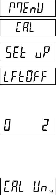
2.6.4 Setup Menu
The CD-11 Indicator SEtuP Menu must be entered the first time the Indicator is used to set the scale base parameters to match the Indicator. Do not attempt to calibrate the Indicator before initially setting up the SEtuP Menu. All other menus should be entered and set up the first time the Indicator is used.
Procedure
With the Indicator ON, press and hold the G/N/T/Menu button until MEnU is displayed. When the G/N/T/Menu button is released, CAL is displayed if the CAL jumper on the PC board is in place. When the CAL jumper is removed, the Indicator will not permit calibration. This jumper should be in place initially.
Press the PRINT/Units button, SEtuP is displayed.
Press the G/N/T/Menu button, LFtOFF is displayed. Legal for trade selections are:
'ON' - LFT (Legal for Trade) is ON 'OFF' - LFT is OFF.
'CAn' - LFT is set for Canada
Press the PRINT/Units button until desired LFT setting is reached.
Press G/N/T/Menu button, 0 2 is displayed. This is the Zero setting. Selections are:
2%: zero operating range is -2% to +2%. 18%: zero operating range is -2% to +18%, 100%: zero operating range is -2% to +100%.
NOTE: If LFT is ON, only 2% and 18% are available.
Press the PRINT/Units button until desired zero setting is reached.
Press the G/N/T/Menu button, CAL Un kg is displayed. This is the calibration unit setting. Selections are:
'lb' - calibration unit is lb 'kg' - calibration unit is kg.
Press the PRINT/Units button until desired calibration unit setting is reached.
EN-12 |
CD-11 Indicator |
2.6.4 Setup Menu (Cont.)
Procedure
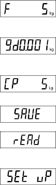
Press the G/N/T/Menu F xx is displayed. This is the full scale capacity setting. xx= value last set. Available selections are are shown in the Setup Table in section 2.6.3.
Press the PRINT/Units button until desired capacity value is reached.
Press the G/N/T/Menu button, gd0.001 is displayed. This is the graduation size setting. Available selections are shown in the Setup Table in section 2.6.3.
Press the PRINT/Units button until desired graduation value is reached.
Press the G/N/T/Menu button, CP 5 kg is displayed. This is the full scale calibration point setting. The range is from 5kg/lb to 100% Full scale capacity.
Press the PRINT/Units button until desired calibration value is reached.
Press the G/N/T/Menu button to end this block, SAVE is displayed.
Press the G/N/T/Menu button to save the menu setup setting. The next menu rEAD is displayed. The Indicator is now matched up with the scale base and the Indicator parameters may now be set and calibrated.
or
Press the PRINT/Units button to return to the SEtuP menu without saving changes.
CD-11 Indicator |
EN-13 |
2.6.5 Readout Menu
The Readout menu is used to adapt the Indicator to environmental conditions and set various features that include: averaging level, stability level, measuring units, parts counting, display hold, auto zero tracking, timer, retain zero data, backlight and a factory service mode. Review all of the settings available before proceeding.
Procedure
To select any of the items in the Readout menu, proceed as follows:
NOTE: If entering from the preceeding menu, disregard the first step.
With the Indicator ON, displayed. When the press the PRINT/Units
press and hold the G/N/T/Menu button until MEnU is G/N/T/Menu button is released, CAL is displayed, then button until rEAd is displayed.
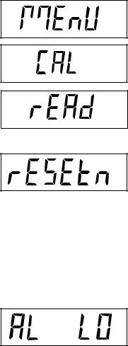
Press the G/N/T/Menu button, rESEtn is displayed. This allows resetting the rEAd menu to factory defaults.
rESEtn = no, does not reset settings.
rESEty= yes, will reset the entire readout menu to factory defaults as follows:
AL Lo, StAb 1, UnOff g, Un On kg, Un On Lb, Un Off oz, Alt Off, AZt 0.5, AOt Off, rZd Off, bLAuto and EP OFF (service mode).
Press the PRINT/Units button for selections N or Y.
AVERAGING LEVEL
Press the G/N/T/Menu button, AL LO is displayed. This is the averaging level settings. Selections are:
'Lo' - Less processing, less stability and faster stabilization time. 'Hi' - More processing, greater stability and slower stabilization time.
(This is the default setting)
Averaging level compensates for vibration or excessive air currents on the scale base. During operation, the Indicator continually takes weight readings from the load cell. Successive readings are then digitally processed to achieve a stabilized display. Using this feature specifies how much processing is needed.
Press the PRINT/Units button until desired averaging level setting is reached.
EN-14 CD-11 Indicator
2.6.5 Readout Menu (Cont.)
STABILITY
Press the G/N/T/Menu button, StAb1 is displayed. This is the stability setting. Selections are:
0.5d Smallest range: stability indicator is ON only when displayed weight is within .5 division.
1d Normal stability (this is the default setting). Fixed for LFT. 3d Higher stability, less sensitive.
The stability range specifies the weighing results and must be within a preset tolerance limit for a certain time to turn the stability indicator ON. When a displayed weight changes beyond the allowable range, the stability indicator turns OFF, indicating an unstable condition.
Press the PRINT/Units button until desired stability setting is reached.
UNITS SELECTION
Press the G/N/T/Menu button, Un OFF g is displayed. This is the unit gram setting.
NOTE: g unit is not available for full scale capacities 100kg and above.
Press the PRINT/Units button for selections ON or OFF. OFF is the default setting.
Press the G/N/T/Menu button, Un ON lb is displayed. This is the unit pound setting. This will be displayed when CAL UNIT kg was selected. When lb was selected as calibration unit, kg will display.
Press the PRINT/Units button for selections ON or OFF. ON is the default setting.
Press the G/N/T/Menu button, Un OFF oz is displayed. This is the unit ounce setting.
Press the PRINT/Units button for selections ON or OFF. OFF is the default setting.
CD-11 Indicator
2.6.5 Readout Menu (Cont.)
ALTERNATE MODE - not available with LFT ON or CAN
Press the G/N/T/Menu button, ALtOFF is displayed. This is the alternate mode setting.
Selections are: OFF Standard weighing (this is the default setting) PC Parts Counting
DH Display Hold - Man (manual)
Semi (semi-automatic) Auto (automatic)
Press the PRINT/Units button until desired alternate mode setting is reached.
Alternate Mode enables either simple parts counting or display hold functions. When ALtdH (display hold) is selected, a choice of manual, semi-automatic or automatic settings are available. The alternate mode can be turned off so that neither mode is available. It is not possible to have both modes activated at the same time. For a complete description of alternate modes, refer to Section 4 Operation.
AUTO ZERO
Press the G/N/T/Menu button, AZt 0.5 is displayed. This is the Auto Zero Threshold setting. Selections are:
0.5d Sets threshold to 0.5 divisions. (this is the default setting) 1d Sets threshold to 1 division.
3d Sets threshold to 3 divisions.
Auto Zero minimizes the effects of temperature changes and small disturbances on the zero reading. The Indicator maintains the zero display until the threshold is exceeded.
Press the PRINT/Units button until desired auto zero threshold setting is reached.
AUTO OFF TIMER
Press the G/N/T/Menu button, AOtOFF is displayed. This is the Auto Off Timer setting. When set ON, the Indicator will shut off automatically after 5 minutes has elapsed on the condition that no button is pressed and the scale base platform is stable during that period.
Press the PRINT/Units button for selections ON or OFF. OFF is the default setting.
EN-15
EN-16 |
CD-11 Indicator |
2.6.5 Readout Menu (Cont.)
RETAIN ZERO DATA
Press the G/N/T/Menu button, Un rZdOFF is displayed. This is the Retain Zero Data setting. When set On, the Indicator stores the current zero point and restores it on the power-up.
Press the PRINT/Units button for selections ON or OFF. OFF is the default setting.
LCD BACK LIGHT
Press the G/N/T/MENU button, bLAutO is displayed. This is the LCD backlight setting. Selections are:
Auto |
Turns off the backlight in 5 seconds (this is the default setting) |
ON |
Backlight is on continuously |
OFF |
Backlight does not turn on |
Press the PRINT/Units button until desired LCD backlight setting is reached.
EP
This is a service function and is not a user-operated feature. OFF is the default setting.
Not available with LFT ON or CAN.
SAVE
Press the G/N/T/MENU button to end this block, SAVE is displayed.
Press the G/N/T/MENU button to save the readout menu settings. The next menu Print is displayed.
or
Press the PRINT/Units button to go back to the SEtuP menu without saving changes.
NOTE: If initial setup, go to the next paragraph. To exit from the SEtuP menu, press the PRINT/Units button to skip to PRINT then to LOCKSW, then Quit. Press the G/N/T/MENU button to go back to the weighing mode.
CD-11 Indicator |
EN-17 |
2.6.6 Print Menu
The Print menu provides data communication settings. It contains 9 submenus: Reset, Baud rate, Parity, Data Length, Stop Bits, Auto Print, Interval, Stable and Save.
Procedure
To select any of the items in the Print menu, proceed as follows:
NOTE: If entering from the preceeding menu, disregard the first step.
With the Indicator ON, displayed. When the press the PRINT/Units
press and hold the G/N/T/Menu button until MEnU is G/N/T/Menu button is released, CAL is displayed, then button until Print is displayed.
Press the G/N/T/Menu button, rESEtn is displayed. This allows resetting the Print menu to factory defaults. rESETn = no, does not reset settings. rESETy=yes, will reset the entire Print menu to factory defaults as follows:
Baud rate =2400, parity =none, data length=7, stop bit=2, Auto Print=AP OFF, if interval is selected=.0001, Stable Print= StbOFF.
Press the PRINT/Units button for selections N or Y.
Press the G/N/T/Menu button, bd2400 displayed. This is the baud rate setting. Selections are: 1200, 2400, 4800, 9600 and 19,200. 2400 is the default setting.
Press the PRINT/Units button until the desired baud rate is reached.
Press the G/N/T/Menu button, PAr nO is displayed. This is the parity bit setting. Selections are:
PAr nO=none (this is the default setting) PAr Odd=odd
PAr E=even
Press the PRINTUnits button until desired parity bit setting is reached.
Press the G/N/T/Menu button, dAtA 7 is displayed. This is the data length setting.
Press the PRINT/Units button for selections dAtA 7 or dAtA 8. Default setting is dAtA 7.
EN-18 CD-11 Indicator
2.6.6 Print Menu (Cont.)
Press the G/N/T/Menu button, StOP 2 is displayed. This is the stop bit setting.
Press the PRINT/Units button for selections StOP 1 or StOP 2. Default setting is
StOP 2.
AUTO PRINT
Press the G/N/T/Menu button, AP OFF is displayed.
This is the Auto print setting which enables data to a printer or PC to be printed automatically. Selection are:
OFF |
(this is the default setting) |
Cont Prints data continuously |
|
Int |
Prints data on user selected intervals |
Stbl |
Print first stable non-zero value after each change in weighing |
|
value. |
Press the PRINT/Units button until desired auto print setting is reached.
INTERVAL PRINTING
When interval has been selected in the previous step, an interval from 1 to 3600 seconds can be set. If Interval was not selected, this submenu does not appear.
Press the G/N/T/Menu button, int is displayed. After a few seconds, a second display appears which allows the interval time in seconds to be set.
Pressing the PRINT/Units button advances the zero from left to right. Pressing the TARE button increments the active digit from 0 to 9.
Sample at right indicates 10 seconds.
NOTE: 0000 not valid.
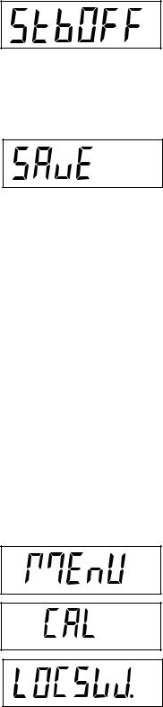
CD-11 Indicator |
EN-19 |
2.6.6 Print Menu (Cont.)
STABLE
Press the G/N/T/Menu button, Stb OFF is displayed.
When set to Stb ON, allows only stable weight values to be printed. When set Stb OFF, prints immediate value with stability indication. In LFT, fixed to Stb ON.
Press the PRINT/Units button for selections Stb ON or Stb OFF. Default setting is
OFF.
SAVE
Press the G/N/T/Menu button to end this block, SAVE is displayed.
Press the G/N/T/Menu button to save the Print menu settings. The next menu
LOCSW is displayed. |
or |
|
Press the PRINT/Units button to go back to the rEAd menu without saving.
NOTE:If initial setup, go to the next paragraph. To exit from the SEtuP, press the PRINT/Units button to skip to LOCKSW, then Quit. Press the G/N/T/Menu button to go back to the weighing mode.
2.6.7 Lockout Menu
The Lockout menu (LOCSW) allows the user to lock and unlock the settings in the CAL, SEtuP, rEAd, and Print menus to prevent tampering or accidental changes. When used in conjunction with the Lock Switch (jumper) on the printed circuit board, the CAL, SEtuP, rEAd and Print menus can be read only and not changed.
Procedure
To select any of the items in the LOCSW menu, proceed as follows:
NOTE: If entering from the preceeding menu, disregard the first step.
With the Indicator ON, displayed. When the press the PRINT/Units
press and hold the G/N/T/Menu button until MEnU is G/N/T/Menu button is released, CAL is displayed, then button until LOCSW is displayed.
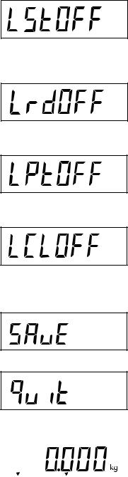
EN-20 |
CD-11 Indicator |
2.6.7 Lockout Menu (Cont.)
Press the G/N/T/Menu button, LStOFF is displayed. This permits locking the SEtuP menu. LStOFF is unlocked, LSt On is read only (locked). This menu is hidden if the CAL jumper is off.
Press the PRINT/Units button for selections LSt ON or LStOFF.
Press the G/N/T/Menu button, LrdOFF displayed. This permits locking the rEAd menu. LrdOFF is unlocked, Lrd On is read only (locked).
Press the PRINT/Units button for selections Lrd On or LrdOFF.
Press the G/N/T/Menu button, LPtOFF is displayed. This permits locking the
Print menu. LPtOFF is unlocked, LPtOn is read only (locked).
Press the PRINT/Units button for selections LPtOn or LPtOFF.
Press the G/N/T/Menu button, LCLOFF is displayed. This permits locking the Calibration menu. LCLOFF is unlocked, LCL On is read only (locked). This menu is hidden if the CAL jumper is off.
Press the PRINT/Units button for selections LCL On or LCLOFF.
Press the G/N/T/Menu button to end this block, SAVE is displayed.
Press the G/N/T/Menu button to save the lockout menu settings. The next menu Quit is displayed.
or
Press the PRINT/Units button to go back to the lockout menu without saving.
After saving the lockout menu settings, press the PRINT/Units button to go to |
> 0 < |
|
|
* |
|
||
CAL or press the G/N/T/Menu button to return to a weighing mode. |
|
|
|
|
|
|
|
|
|
|
|
NOTE: At this point, the Indicator must be calibrated and the jumper removed |
|
Stable |
Gross |
|
|
Brutto |
|
from the CAL connector in order to lock the menus. The top cover of the Indica- |
|
|
|
tor should be free to gain access to the CAL jumper. |
|
|
|
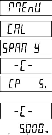
CD-11 Indicator |
EN-21 |
3. CALIBRATION AND SEALING
Model CD-11 Indicator requires span calibration before using. Span calibration ensures that the Indicator reads correctly within specifications. For best results, calibrate at or near full capacity. Calibration unit can be set to either kg or lb.
NOTE: When the Indicator is used in Legal for Trade or legally controlled applications, the calibration menu is locked out and is not accessible. This is to prevent unauthorized personnel from changing calibration.
Before beginning calibration, make sure masses are available. If you begin calibration and realize calibration masses are not available, exit the menu. The Indicator will retain previously stored calibration data. Calibration should be performed as necessary to ensure accurate weighing. Masses required to perform the procedures should be in compliance with the requirements of the scale base being used with the Indicator.
You have a choice of either span or linearity calibration. Span calibration checks zero and full span calibration points. Linearity calibration checks zero, mid span and full span points.
Procedure
SPAN CALIBRATION
With the Indicator ON, press and hold the G/N/T/Menu button until MEnU is displayed. When the G/N/T/Menu button is released, CAL is displayed.
Press the G/N/T/Menu button, SPAN Y is displayed.
Press the G/N/T/Menu button, -C- is displayed. The scale base MUST be stable during this period as it establishes a zero point. After a few seconds, the requested weight value is displayed. The sample illustration indicates a 5kg weight value (Cal Point CP was set for 5kg).
Place the indicated mass on the platform. Keep the platform stable during this period.
Press the G/N/T/Menu button, -C- is displayed while the Indicator stores the reading and then displays the weight of the mass.
If the calibration was successful, the calibration weight is displayed and the calibration data is saved automatically. If unsuccessful, refer to the troubleshooting section.
Remove calibration masses from the platform.
|
|
Stable |
Gross |
|
Brutto |
NOTE: If the Indicator is to be used for legal for trade or legally controlled applications, it must be calibrated and the jumper removed from the CAL connector in order to lock the menus. The top cover of the Indicator should be free to gain access to the CAL jumper. Refer to section 3.1 for sealing for legal for trade use.
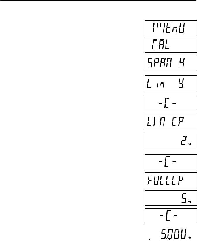
EN-22 CD-11 Indicator
Procedure
LINEARITY CALIBRATION
With the Indicator ON, press and hold the button G/N/T/Menu until MEnU is displayed. When the G/N/T/Menu button is released, CAL is displayed.
Press the G/N/T/Menu button, SPAN Y is displayed.
Press the PRINT/Units button, Lin Y is displayed.
Press the G/N/T/Menu button, -C- is displayed. The scale base MUST be stable during this period as it establishes a zero point. After a few seconds, the display flashes LIN CP twice and the requested weight value is displayed. The sample illustration indicates a 2kg center point for a 5kg scale.
Place the indicated mass on the platform. Keep the platform stable during this period.
Press the G/N/T/Menu button, -C- is displayed. The scale base MUST be stable during this period as it establishes a center point. After a few seconds, the display flashes FULLCP twice and the requested weight value is displayed.
Place the indicated mass on the platform and press the G/N/T/Menu button -C- is displayed.
If linearity calibration was successful, the calibration weight is displayed and |
|
|
|
|
|
||
the calibration data is saved automatically. If unsuccessful, refer to the trouble- |
|
|
|
shooting section. |
|
|
|
|
|
|
|
|
|
Stable |
Gross |
Remove calibration masses from platform. |
Brutto |
||
|
|||
NOTE: If the Indicator is to be used for legal for trade or legally controlled applications, it must be calibrated and the jumper removed from the CAL connector in order to lock out the menus. The top cover of the Indicator should be free to gain access to the CAL jumper. Refer to section 3.1 for sealing for legal for trade use.
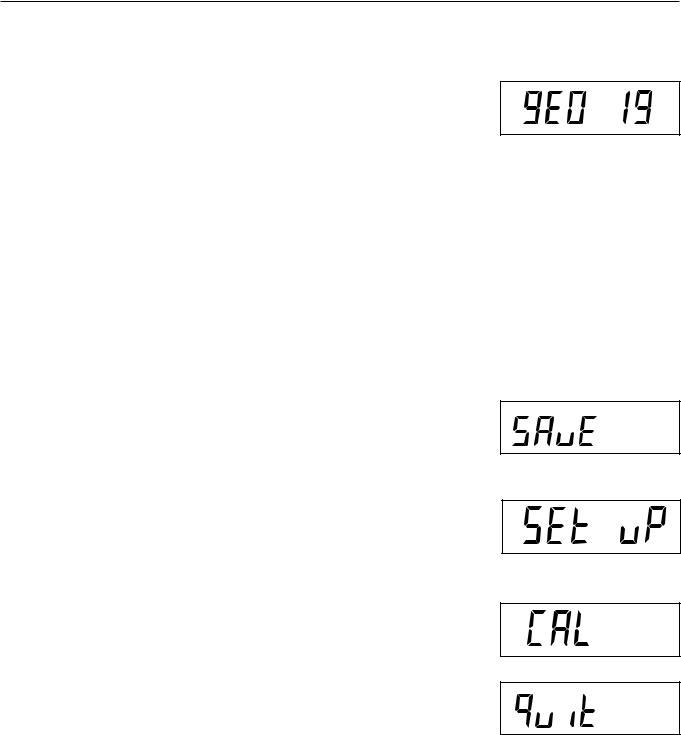
CD-11 Indicator
GEOGRAPHICAL FACTOR (For Europe Only)
Press the G/N/T/Menu button, gEO 19 is displayed. This is the current geographical adjustment value.
The geo factor includes settings from 0 to 31 and is used to compensate for varying gravity at different geographical areas (complete geographical adjustment settings are listed in the following table).
NOTE:
Only an authorized manufacturer’s representative or certified verification personnel may make these changes.
Changing the geographical setting alters the calibration values.
Press the Print/Units button until the desired geographical adjustment value is reached. The factory default setting is gEO 19
SAVE
Press the G/N/T/Menu button to end this block, SAVE is displayed.
Press the G/N/T/Menu button to save the geographical factor setting. The next menu SEt uP is displayed.
or
Press the Print/Units button to go back to the CAL menu without saving changes to the geographical setting.
QUIT
To exit from the CAL menu, press the Print/Units button to advance to Quit. Then press the G/N/T/Menu button to go back to the weighing mode.
EN-23

|
|
EN-24 |
|
|
|
|
|
|
|
|
CD-11 Indicator |
|
||
GEOGRAPHICAL FACTOR (cont.) |
GEOGRAPHICAL ADJUSTMENT VALUES |
|
|
|
|
|
||||||||
|
|
|
|
|
|
|
|
|
|
|||||
|
|
|
|
|
|
|
|
|
|
|
|
|
|
|
|
|
|
|
Elevation above sea level in meters |
|
|
|
|
|
|
|
|
|
|
|
|
|
0 |
325 |
650 |
975 |
1300 |
1625 |
1950 |
2275 |
2600 |
2925 |
3250 |
|
|
|
Geographical latitude in |
325 |
650 |
975 |
1300 |
1625 |
1950 |
2275 |
2600 |
2925 |
3250 |
3575 |
|
|
|
the northern or southern |
|
Elevation above sea level in feet |
|
|
|
|
|
|
|
|
|
|
|
|
hemisphere in degrees |
0 |
1060 |
2130 |
3200 |
4260 |
5330 |
6400 |
7460 |
8530 |
9600 |
10660 |
|
|
|
and minutes |
1060 |
2130 |
3200 |
4260 |
5330 |
6400 |
7460 |
8530 |
9600 |
10660 |
11730 |
|
|
|
0°0'-5°46’ |
5 |
4 |
4 |
3 |
3 |
2 |
2 |
1 |
1 |
0 |
0 |
|
|
|
5°46'-9°52’ |
5 |
5 |
4 |
4 |
3 |
3 |
2 |
2 |
1 |
1 |
0 |
|
|
|
9°52'-12°44’ |
6 |
5 |
5 |
4 |
4 |
3 |
3 |
2 |
2 |
1 |
1 |
|
|
|
12°44'-15°6’ |
6 |
6 |
5 |
5 |
4 |
4 |
3 |
3 |
2 |
2 |
1 |
|
|
|
15°6'-17°10’ |
7 |
6 |
6 |
5 |
5 |
4 |
4 |
3 |
3 |
2 |
2 |
|
|
|
17°10'-19°2’ |
7 |
7 |
6 |
6 |
5 |
5 |
4 |
4 |
3 |
3 |
2 |
|
|
|
19°2'-20°45’ |
8 |
7 |
7 |
6 |
6 |
5 |
5 |
4 |
4 |
3 |
3 |
|
|
|
20°45'-22°22’ |
8 |
8 |
7 |
7 |
6 |
6 |
5 |
5 |
4 |
4 |
3 |
|
|
|
22°22'-23°54’ |
9 |
8 |
8 |
7 |
7 |
6 |
6 |
5 |
5 |
4 |
4 |
|
|
|
23°54'-25°21’ |
9 |
9 |
8 |
8 |
7 |
7 |
6 |
6 |
5 |
5 |
4 |
|
|
|
25°21'-26°45’ |
10 |
9 |
9 |
8 |
8 |
7 |
7 |
6 |
6 |
5 |
5 |
|
|
|
26°45'-28°6’ |
10 |
10 |
9 |
9 |
8 |
8 |
7 |
7 |
6 |
6 |
5 |
|
|
|
28°6'-29°25’ |
11 |
10 |
10 |
9 |
9 |
8 |
8 |
7 |
7 |
6 |
6 |
|
|
|
29°25'-30°41’ |
11 |
11 |
10 |
10 |
9 |
9 |
8 |
8 |
7 |
7 |
6 |
|
|
|
30°41'-31°56’ |
12 |
11 |
11 |
10 |
10 |
9 |
9 |
8 |
8 |
7 |
7 |
|
|
|
31°56'-33°9’ |
12 |
12 |
11 |
11 |
10 |
10 |
9 |
9 |
8 |
8 |
7 |
|
|
|
33°9'-34°21’ |
13 |
12 |
12 |
11 |
11 |
10 |
10 |
9 |
9 |
8 |
8 |
|
|
34°21' - 35° 31' |
13 |
13 |
12 |
12 |
11 |
11 |
10 |
10 |
9 |
9 |
8 |
|
|
|
35°31' - 36° 41' |
14 |
13 |
13 |
12 |
12 |
11 |
11 |
10 |
10 |
9 |
9 |
|
|
|
36°41' - 37° 50' |
14 |
14 |
13 |
13 |
12 |
12 |
11 |
11 |
10 |
10 |
9 |
|
|
|
37°50' - 38° 58' |
15 |
14 |
14 |
13 |
13 |
12 |
12 |
11 |
11 |
10 |
10 |
|
|
|
38°58' - 40° 5' |
15 |
15 |
14 |
14 |
13 |
13 |
12 |
12 |
11 |
11 |
10 |
|
|
|
40° 5' - 41° 12' |
16 |
15 |
15 |
14 |
14 |
13 |
13 |
12 |
12 |
11 |
11 |
|
|
|
41°12' - 42° 19' |
16 |
16 |
15 |
15 |
14 |
14 |
13 |
13 |
12 |
12 |
11 |
|
|
|
42°19' - 43° 26' |
17 |
16 |
16 |
15 |
15 |
14 |
14 |
13 |
13 |
12 |
12 |
|
|
|
43°26' - 44° 32' |
17 |
17 |
16 |
16 |
15 |
15 |
14 |
14 |
13 |
13 |
12 |
|
|
|
44°32' - 45° 38' |
18 |
17 |
17 |
16 |
16 |
15 |
15 |
14 |
14 |
13 |
13 |
|
|
|
45°38' - 46° 45' |
18 |
18 |
17 |
17 |
16 |
16 |
15 |
15 |
14 |
14 |
13 |
|
|
|
46°45' - 47° 51' |
19 |
18 |
18 |
17 |
17 |
16 |
16 |
15 |
15 |
14 |
14 |
|
|
|
47°51' - 48° 58' |
19 |
19 |
18 |
18 |
17 |
17 |
16 |
16 |
15 |
15 |
14 |
|
|
|
48°58' - 50° 6' |
20 |
19 |
19 |
18 |
18 |
17 |
17 |
16 |
16 |
15 |
15 |
|
|
|
50° 6' - 51° 13' |
20 |
20 |
19 |
19 |
18 |
18 |
17 |
17 |
16 |
16 |
15 |
|
|
|
51°13' - 52° 22' |
21 |
20 |
20 |
19 |
19 |
18 |
18 |
17 |
17 |
16 |
16 |
|
|
|
52°22' - 53° 31' |
21 |
21 |
20 |
20 |
19 |
19 |
18 |
18 |
17 |
17 |
16 |
|
|
|
53°31' - 54° 41' |
22 |
21 |
21 |
20 |
20 |
19 |
19 |
18 |
18 |
17 |
17 |
|
|
|
54°41' - 55° 52' |
22 |
22 |
21 |
21 |
20 |
20 |
19 |
19 |
18 |
18 |
17 |
|
|
|
55°52' - 57° 4' |
23 |
22 |
22 |
21 |
21 |
20 |
20 |
19 |
19 |
18 |
18 |
|
|
|
57° 4' - 58° 17' |
23 |
23 |
22 |
22 |
21 |
21 |
20 |
20 |
19 |
19 |
18 |
|
|
|
58°17' - 59° 32' |
24 |
23 |
23 |
22 |
22 |
21 |
21 |
20 |
20 |
19 |
19 |
|
|
|
59°32' - 60° 49' |
24 |
24 |
23 |
23 |
22 |
22 |
21 |
21 |
20 |
20 |
19 |
|
|
|
60°49' - 62° 9' |
25 |
24 |
24 |
23 |
23 |
22 |
22 |
21 |
21 |
20 |
20 |
|
|
|
62° 9' - 63° 30' |
25 |
25 |
24 |
24 |
23 |
23 |
22 |
22 |
21 |
21 |
20 |
|
|
|
63°30' - 64° 55' |
26 |
25 |
25 |
24 |
24 |
23 |
23 |
22 |
22 |
21 |
21 |
|
|
|
64°55' - 66° 24' |
26 |
26 |
25 |
25 |
24 |
24 |
23 |
23 |
22 |
22 |
21 |
|
|
|
66°24' - 67° 57' |
27 |
26 |
26 |
25 |
25 |
24 |
24 |
23 |
23 |
22 |
22 |
|
|
|
67°57' - 69° 35' |
27 |
27 |
26 |
26 |
25 |
25 |
24 |
24 |
23 |
23 |
22 |
|
|
|
69°35' - 71° 21' |
28 |
27 |
27 |
26 |
26 |
25 |
25 |
24 |
24 |
23 |
23 |
|
|
|
71°21' - 73° 16' |
28 |
28 |
27 |
27 |
26 |
26 |
25 |
25 |
24 |
24 |
23 |
|
|
|
73°16' - 75° 24' |
29 |
28 |
28 |
27 |
27 |
26 |
26 |
25 |
25 |
24 |
24 |
|
|
|
75°24' - 77° 52' |
29 |
29 |
28 |
28 |
27 |
27 |
26 |
26 |
25 |
25 |
24 |
|
|
|
77°52' - 80° 56' |
30 |
29 |
29 |
28 |
28 |
27 |
27 |
26 |
26 |
25 |
25 |
|
|
|
80°56' - 85° 45' |
30 |
30 |
29 |
29 |
28 |
28 |
27 |
27 |
26 |
26 |
25 |
|
|
|
85°45' - 90° 00' |
31 |
30 |
30 |
29 |
29 |
28 |
28 |
27 |
27 |
26 |
26 |
|
|
|
|
|
|
|
|
|
|
|
|
|
|
|
|
|
 Loading...