


Essentia™
Six-Source, Six-Zone Audio Distribution System
NV-E6DMS/NV-E6DXS Owners Manual
ENGLISH
Danger
Exposure to extremely high noise levels may cause a permanent hearing loss. Individuals vary considerably to noise induced hearing loss but nearly everyone will lose some hearing if exposed to sufficiently intense noise for a sufficient time. The U.S. Government's Occupational Safety and Health Administration (OSHA) has specified the following permissible noise level exposures:
DURATION PER DAY (HOURS) |
8 6 |
4 3 2 1 |
|
|
|
SOUND LEVEL (dB) |
90 93 |
95 97 100 103 |
|
|
|
According to OSHA, any exposure in the above permissible limits could result in some hearing loss. Ear plugs or protectors in the ear canal or over the ears must be worn when operating this amplification system in order to prevent a permanent hearing loss. If exposure in excess of the limits as put forth above, to insure against potentially harmful exposure to high sound pressure levels, it is recommended that all persons exposed to equipment capable of inducing high sound pressure levels, such as this amplification system, be protected by hearing protectors while this unit is in operation.
CAUTION |
RISK OF ELECTRIC SHOCK |
DO NOT OPEN |
CAUTION: TO REDUCE THE RISK OF ELECTRIC SHOCK, DO |
NOT REMOVE CHASSIS. NO USER-SERVICEABLE |
PARTS INSIDE. REFER SERVICING TO QUALIFIED |
SERVICE PERSONNEL. |
AVIS: RISQUE DE CHOC ELECTRIQUE-NE PAS OUVRIR.
THIS SYMBOL IS INTENDED TO ALERT THE USER TO THE PRESENCE OF NON-INSULATED "DANGEROUS VOLTAGE" WITHIN THE PRODUCT'S ENCLOSURE THAT MAY BE OF SUFFICIENT MAGNITUDE TO CONSTITUTE A RISK OF ELECTRIC SHOCK TO PERSONS.
THIS SYMBOL IS INTENDED TO ALERT THE USER TO THE PRESENCE OF IMPORTANT OPERATING AND MAINTENANCE (SERVICING) INSTRUCTIONS IN THE LITERATURE ACCOMPANYING THE UNIT.
APPARATUS SHALL NOT BE EXPOSED TO DRIPPING OR SPLASHING AND THAT NO OBJECTS FILLED WITH LIQUIDS, SUCH AS VASES, SHALL BE PLACED ON THE APPARATUS.
IMPORTANT SAFETY INSTRUCTIONS
1.Read all safety and operating instructions before using this product.
2.All safety and operating instructions should be kept for future reference.
3.Read and understand all warnings listed on the operating instructions.
4 . Follow all operating instructions to operate this product.
5.This product should not be used near water, i.e. Bathtub, sink,swimming pool, wet basement, etc.
6.Only use dry cloth to clean this product.
7.Do not block any ventilation openings, It should not be placed flat against a wall or placed in a built-in enclosure that will impede the flow of cooling air.
8.Do not install this product near any heat sources ;such as,radiators, heat registers, stove or other apparatus (including heat producing amplifiers) that produce heat.
9.Do not defeat the safety purpose of the polarized or groundingtype plug. A polarized plug has two blades with one wider than the 0ther.A grounding-type plug has two blades and a third grounding prong. The wide blade or the third prong are provided for your safety If the provided plug does not fit into your outlet, consult an electrician for replacement of the obsolete outlet.
10.Protect the power cord being walked on or pinched, particularly at Plugs, convenience receptacles and the point where they exit from the apparatus. Do not break the ground pin of the power supply cord.
11 . Only use attachments specified by the manufacturer.
12.Use only with the cart, stand, tripod, bracket, or table specified by the manufacturer or sold with the apparatus. When a cart is used, use caution when moving cart/apparatus combination to avoid injury from tip-over.
13.Unplug this apparatus during lightning storms or when unused for long periods of time.
14.Care should be taken so that objects do not fall and liquids are not spilled into the unit through the ventilation ports or any other openings.
15.Refer all servicing to qualified service personnel. Servicing is required when the apparatus has been damaged in any way; such as, power-supply cord or plug is damaged, liquid has been spilled or objects have fallen into the apparatus, the apparatus has been exposed to rain or moisture, does not operate normally or has been dropped.
16.WARNING: To reduce the risk of fire or electric shock, do not expose this apparatus to rain or moisture.
FRENCH
Danger
L‘exposition a des niveaux eleves de bruit peut provoquer une perte permanente de l’audition, Chaque organisme humain reagit differemment quant a la perte de l’audition, mais quasiment tout le monde subit une diminution de I’acuite auditive lors d’une exposition suffisamment longue au bruit intense. Les autorites competentes en reglementation de bruit ont defini les expositions tolerees aux niveaux de bruits:
DURE EN HEURES PAR JOUR |
8 6 |
4 3 2 |
1 |
|
|
|
|
INIVEAU SONORE CONTINU EN dB |
90 93 |
95 97 100 |
103 |
|
|
|
|
Selon les autorites, toute exposition dans les limites citees ci-dessus, peuvent provoquer certaines pertes d’audition. Des bouchons ou protections dans l’appareil auditif ou sur l’oreille doivent etre portes lors de l’utilisation de ce systeme d’amplification afin de prevenir le risque de perte permanente de l’audition, Dans le cas d’expositions superieures aux limites precitees il est recommande, afin de se premunir contre les expositions aux pressions acoustiquese I evees potentielIement dangeure u ses, aux personnes exposees aux equipements capables de delivrer de telles puissances, tels ce systeme d’amplification en fonctionnement, de proteger l’appareil auditif.
ATTENTION
RISQUE DE CHOC ELECTRIQUE
NE PAS OUVRIR.
ATTENTION: AFIN DE LlMlTER LE RISQUE DE CHO ELECTR/QUE, NE
PAS ENLEVER LE CHASSIS. NE CONTIENT PAS DE
PIECES POUVANT ETRE REPAREE PAR L’UTILISATEUR.
CONFER LE SERVICE APRES-VENTE AUX
REPARATEURS
CE SYMBOLE A POUR BUT D'AVERTIR L'UTILISATEUR DE LA PRESENCE DE VOLTAGE DANGEREUX NON-ISOLE A L'INTERIEUR DE CE PRODUIT QUI PEUT ETRE DE PUISSANCE SUFFISAMMENT IMPORTANTE POUR PROVOQUER UN CHOC ELECTRIQUE AUX PERSONNES.
CE SYMBOLE A POUR BUT D'AVERTIR L'UTILISATEUR DE LA PRESENCE D'INSTRUCTIONS D'UTILISATION ET DE MAINTENANCE DANS LES DOCUMENTS FOURNIS AVEC CE PRODUIT.
AFIN DE REDUIRE LES RISQUÉ D'INCENDIE ET DE DECHARGE ELECTRIQUE, NE PAS EXPOSER CET APPAREIL A LA PLUIE OU A L'HUMIDITE.
IMPORTANTES INSTRUCTIONS DE SECURITE
1.Lire avec attention toutes les recommandations et précautions d'emploi avant d'utiliser ce produit.
2.Toutes les recommandations et précautions d'emploi doivent être conservées afin de pouvoir s'y reporter si nécessaire.
3.Lire et comprendre tous les avertissements énumérés dans les précautions d'emploi.
4.Suivre toutes les précautions d'emploi pour utiliser ce produit.
5.Ce produit ne doit pas être utilisé près d'eau, comme par exemple baignoires, éviers, piscine, sous-sol humides ... Etc.
6.Utiliser exclusivement un chiffon sec pour nettoyer ce produit.
7.Ne bloquér aucune ouverture de ventilation. Ne pas placer le produit tout contre un mur ou dans une enceinte fernée, cela gênerait le flux d'air nécessaire au refroidissement.
8.Ne pas placer le produit près de toute source de chaeur telle que radiateurs, arrivées d'air chaud, fourneaux ou autres appareils générant de la chaleur (incluant les amplificateurs producteurs de chaleur) .
9.Ne pas négliger la sécurité que procure un branchement polarisé ou avec raccordement à la terre, Un branchement polarisé comprend deux fiches dont l'une est plus large que l'autre. Un branchement à la terre comprend deux fiches plus une troisième reliée à la terre. Si la fiche secteur fournie ne s'insert pas dans votre prise de courant. consulter un 'électricien afin de remplacer votre prise obsolète.
10.Protéger le cordon d'alimentation de tout écrasement ou pincement, particulièrement au niveau des fiches, des réceptacles utilisés et à l'endroit de sortie de l'appareil. Ne pas casser la fiche de terre du cordon d'alimentation.
11.Utiliser uniquement les accessoires spécifiés par le constructeur.
12.Utiliser uniquement avec le chariot de transport, le support, le trépied, la console ou la table spécifiés par le constructeur ou vendus avec l'appareil. Lors de l'utilisation d'un chariot, bouger avec précaution l'ensemble chariotlappareil afin d'éviter les dommages d'un renversement.
13Débrancher cet appareil lors d'orages ou s'il n'est pas utilisé pendant une longue période.
14.Des précautions doivent être prises afin qu'aucun objet ne tombe et qu'aucun liquide ne se répande à l'intérieur de l'appareil par les orifics de ventilation ou n'importe quelle autre ouverture.
15.Pour toutes interventions techniques s'adresser à un technicien qualifié.L'intervention technique est nécessaire lorsque l'appareil a été endommagé de n'importe quelle façon, comme par exemple si le cordon secteur ou sa fiche sont détériorés,si du liquide a coulé ou si des objets sont tombés à l'intérieur de l'apparei1,si l'appareil a été exposé à la pluie ou à l'humidité, s'il ne fonctionne pas normalement ou s'il est tombé.
16.ATTENTI0N:Pour réduire le risque d'incendie ou de choc electrique ne pas exposer l'appareil à la pluie ou à l'humidité.

Essentia
Six-Source, Six-Zone Audio Distribution System
NV-E6DMS/NV-E6DXS Owners Manual
Introduction
Congratulations on your purchase of the NuVo Essentia audio distribution system. Essentia offers the newest in digital audio technology in an attractive, easy-to-install, and simple-to-use package. Generation D digital amplification means that Essentia is able to create clear, precise sound without producing a large amount of heat.
Because digital amplification is far more efficient, Essentia draws only one third of the power of conventional analogue amplifiers.
The Essentia system is designed for the homeowner. Its attractive backlit keypads are elegant, easy-to-operate, and able to be customized for any installation. Included with each keypad are white, ivory, and almond cover plates to best match your home’s décor. Also included with each keypad are twenty preprinted audio source buttons for customizing your system for your use.
Using the Essentia is as easy as the push of a button. Each listening zone can be turned on or off independently, or all zones can be turned off simultaneously by using the "ALL OFF" button at any one of the keypads. Individual volume control for each zone is also as easy as the push of a button.
The built-in IR receiver allows for direct access to all of your audio source equipment by utilizing the individual audio component’s hand-held remote, or you can also enjoy the convenience of having all of the commands of your audio source equipment in one universal learning remote. The RC2 remote control shipped with the Essentia package is the perfect tool for teaching learning remotes functions of the Essentia keypads. This puts complete control of your NuVo system in the palm of your hand.
The following pages of this manual provide step-by-step instructions for installing your Essentia System. Reading and understanding this installation guide will insure a proper installation and years of audio enjoyment.
4
Zone/Room 1 |
Zone/Room 2 |
Zone/Room 3 |
Zone/Room 4 |
Zone/Room 5 |
Zone/Room 6 |
EZ Port Cat-5 connection
C C C
C C C
C C C
C C C
C C C
C C C
C C C
C C C
C C C
C C C
C C C
C C C
C C C
C C C
C C C
C C C
C C C
C C C
C C C
C C C
C C C
C C C
C C C
C C C
C C C
C C C
C C C
C C C
C C C
|
|
|
|
|
|
120V |
60HZ |
250 WATTS |
|
|
AUDIO |
|
|
CONTROL |
SPEAKER |
|
|
Single Network cable |
|
|
|
|
|
|
|
USE ONLY WITH 250V FUSE |
connection to the |
||
|
L |
SENSITIVITY |
MODE |
TRIGGER ON |
8 OHM: 70W X 2 |
|
|
||
|
|
OdBV = 1.0RMS |
POWER |
VOLTAGE UNIT |
OUTPUT POWER |
|
|
|
|
|
INPUT |
LEFT |
RIGHT |
ON/OFF SWITCH 3-30 VOLTS +12VDC |
4 OHM: 100W X 2 |
|
|
|
|
|
AUDIO AC/DC |
AC OR DC 100mA |
|
|
|
Essentia Amplifier |
|||
|
R |
+6 |
-12 +6 |
-12 |
|
|
|
|
|
|
2 |
0 |
0 |
|
|
|
|
|
|
INPUT |
OUTPUT |
|
|
|
|
|
|
|
|
VARIABLE |
|
VARIABLE |
|
VARIABLE |
|
VARIABLE |
|
VARIABLE |
|
VARIABLE |
|
|
OUTPUT |
|
OUTPUT |
|
OUTPUT |
|
OUTPUT |
|
OUTPUT |
|
OUTPUT |
|
RS-232 |
TIP=L |
OUTPUT POWER |
TIP=L |
OUTPUT POWER |
TIP=L |
OUTPUT POWER |
TIP=L |
OUTPUT POWER |
TIP=L |
OUTPUT POWER |
TIP=L |
OUTPUT POWER |
|
20W/6OHM X2 |
20W/6OHM X2 |
20W/6OHM X2 |
20W/6OHM X2 |
20W/6OHM X2 |
20W/6OHM X2 |
|
||||||
RING=R |
|
RING=R |
|
RING=R |
|
RING=R |
|
RING=R |
|
RING=R |
|
|
|
FIXED |
|
|
|
FIXED |
FIXED |
FIXED |
|
FIXED |
|
|
|
FIXED |
|
|
|
|
|
OUTPUT |
|
|
|
OUTPUT |
OUTPUT |
OUTPUT |
|
OUTPUT |
|
|
|
OUTPUT |
|
|
|
|
|
ZONE 1 |
|
|
ZONE 2 |
ZONE 3 |
ZONE 4 |
|
ZONE 5 |
|
|
ZONE 6 |
|
|
|
PROGRAM |
||
1 |
2 |
3 |
4 |
5 |
6 |
CONNECT TO |
1 |
1 |
3 |
5 |
1 |
3 |
5 |
SUM1 |
SYS ON |
CONNECT TO |
CONNECT TO |
|
|
|
|
|
|
NV-I8X |
|
|
|
|
|
|
|
|
|
NV-I8EZP1 |
NV-I8X |
|
|
|
|
|
|
USE NV-SLC1 |
|
|
|
|
|
|
|
|
|
USE NV-NC1 |
USE NV-SLC1 |
|
|
|
|
|
|
|
|
|
|
|
|
|
|
|
CABLE |
||
|
|
|
|
|
|
CABLE |
|
|
|
|
|
|
|
|
|
|
CABLE |
1 |
2 |
3 |
4 |
5 |
6 |
|
5 |
2 |
4 |
6 |
2 |
4 |
6 |
SUM2 |
EXT. MUTE |
|
|
|
|
SOURCE INPUTS |
|
|
SOURCE LINK |
|
ZONE TRIGGER OUTPUTS |
|
EMITTER OUTPUTS |
|
SYSTEM |
NETWORK |
DIGITAL LINK |
||||
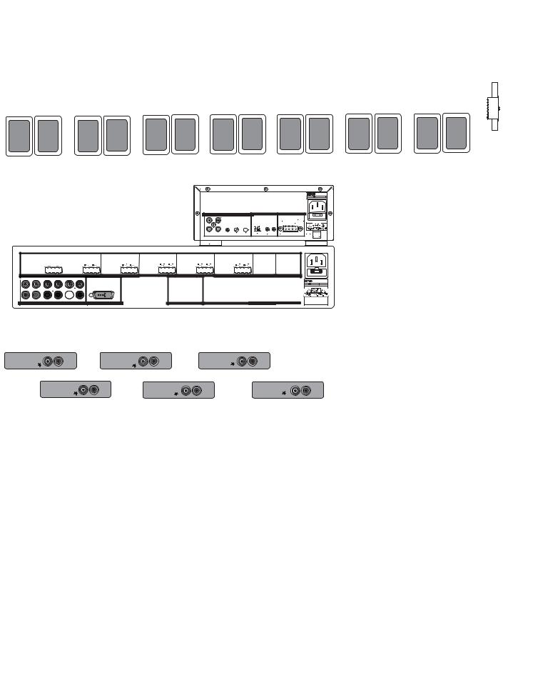
Diagram shown with optional NuVo NV-P2100 auxiliary amplifier powering zone 6.
Source 1 |
Audio |
Source 3 |
Audio |
Source 5 |
Audio |
|
Tuner 1 |
Out |
Tuner 3 |
Out |
CD 2 |
Out |
|
|
Source 2 |
Audio |
Source 4 |
Audio |
Source 6 |
Audio |
|
Tuner 2 |
Out |
CD 1 |
Out |
Sat. |
Out |
Essentia D
Wiring Diagram
5

Quick Start Guide
Your Essentia Audio Distribution System is quick and easy to install. This guide outlines the necessary steps for an accurate and successful installation, and years of audio enjoyment.
Step 1:
Check your package for all of the components. Your box should contain the following items:
1 |
NV-E6DMS 6-source, 6-zone digital audio distribution amplifier |
6 |
NV-E6DKPC keypads, with 1 bag of preprinted source buttons, ivory, and almond |
|
replacement keypad inserts for each |
1 |
NV-RC2 remote control with batteries |
1 |
NV-NEC 10 foot network cable |
1 |
NV-E6DEZP EZ Port connection hub |
6 |
NV-VEC IR emitters |
1AC power cord
1Installation manual
Step 2:
Place the Essentia amplifier in its preferred location. The Essentia amplifier is designed to be located in the central media area where the home’s audio sources will be housed.
Step 3:
The Essentia amplifier should be turned on before any other cables are plugged in. This activates internal protective circuitry. Once the Essentia amplifier is turned on, it should be left on.
Step 4:
When the amplifier is in its location and turned on, the audio sources can be connected using stereo RCA cables. These cables connect the left and right channels from the audio output of the source equipment to the appropriate source input on the Essentia amplifier. The IR (infrared) emitters should be plugged into the IR outputs on the back of the amplifier and attached to the IR window of the corresponding source equipment.
Step 5:
Each of the Cat-5 cables from the zones should be crimped with an RJ-45 connector using 568A or 568B wiring (see page for Cat-5 crimping instructions). Test each Cat-5 connection using a cable tester before proceeding with the installation. Each cable plugs into one of the RJ-45 connection jacks on the back of the supplied EZ Port. It is important for future reference to label each cat-5 cable for its appropriate listening zone. The order in which they are plugged into the EZ Port is irrelevant to the system’s operation.
Step 6:
Install the EZ Port in a standard dual gang low voltage bracket. We recommend the Carlon SC100R "Old Work Bracket", or the SC100A "New Construction Bracket". These are designed for low voltage electronics and have an open back for easy access to the back of the EZ Port.
6

Step 7:
Connect the provided pre-terminated network Cable in the RJ-45 connection jack on the front of the EZ Port and in the Network Connection on the back of the Essentia amplifier.
Step 8:
Each zone is easily set using the DIP switches located on the back of the keypad. Switches 1-4 are used to set a unique address for each zone and are noted with a "1" indicating the down position of the switch and a "O" indicating the up position. Refer to the chart on the back of the keypad for the correct switch position for each zone. Page 17 provides a visual reference of all of the available switch settings.
Step 9:
Switches 5, 6, & 7 are used to adjust the amount of bass and treble response in each zone. There are eight possible settings. The choices are a bass and treble boost, two levels of bass boost, two levels of treble boost, bass cut, treble cut, or flat. The positions for these settings are also shown as "1" for down and "O" for up and are shown on page 18.
Step 10:
Switch 8 allows multiple zones to share the same source. This is useful for large living spaces such as a kitchen, breakfast nook, and dinning room where there are no walls defining each room. When switch 8 is in the up "O" position, all keypads with the same setting will then always turn on at the same source. This does, however, allow individual volume and on/off control. This setting is shown on page 18.
Step 11:
Switch 9 sets the volume level when the zone is turned on. The choices are to have the zone turn on at the same level it was at when it was previously turned off (switch 9 in the down "1" position), or to turn on at a low volume level (switch 9 in the up "O" position). This setting is shown on page 19.
Step 12:
Once the desired switch settings have been made for each keypad and they have been installed in their zone locations, you will be able to turn each zone on and off, control volume, and choose audio sources independently. These functions can also be done wirelessly using the NuVo RC2 remote control. The built-in IR receiver in each keypad also allows for direct control of the audio source equipment using that equipment’s remote control or a universal learning remote control.
7
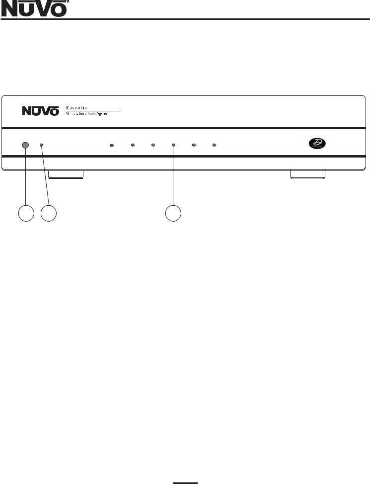
Essentia
Amplifier Front Panel
POWER |
STAND BY |
ZONE 1 |
ZONE 2 |
ZONE 3 |
ZONE 4 |
ZONE 5 |
ZONE 6 |
1 |
2 |
3 |
1.POWER Button: The amplifier is designed to be turned on and remain on. The power button
supplies power to the system. Each zone can then be turned on or off independently. The amplifier should be turned on before any external connections are made. This activates internal protective circuitry. With all the zones turned off the resulting "standby" power consumption is extremely low.
2.STAND BY LED: This blue LED (light-emitting diode) will indicate that the amplifier is plugged
in to an AC outlet source.
3.Zone Status LED’s: These LED’s indicate the power status of each zone. When a zone LED is lit,
that zone is currently turned on.
8
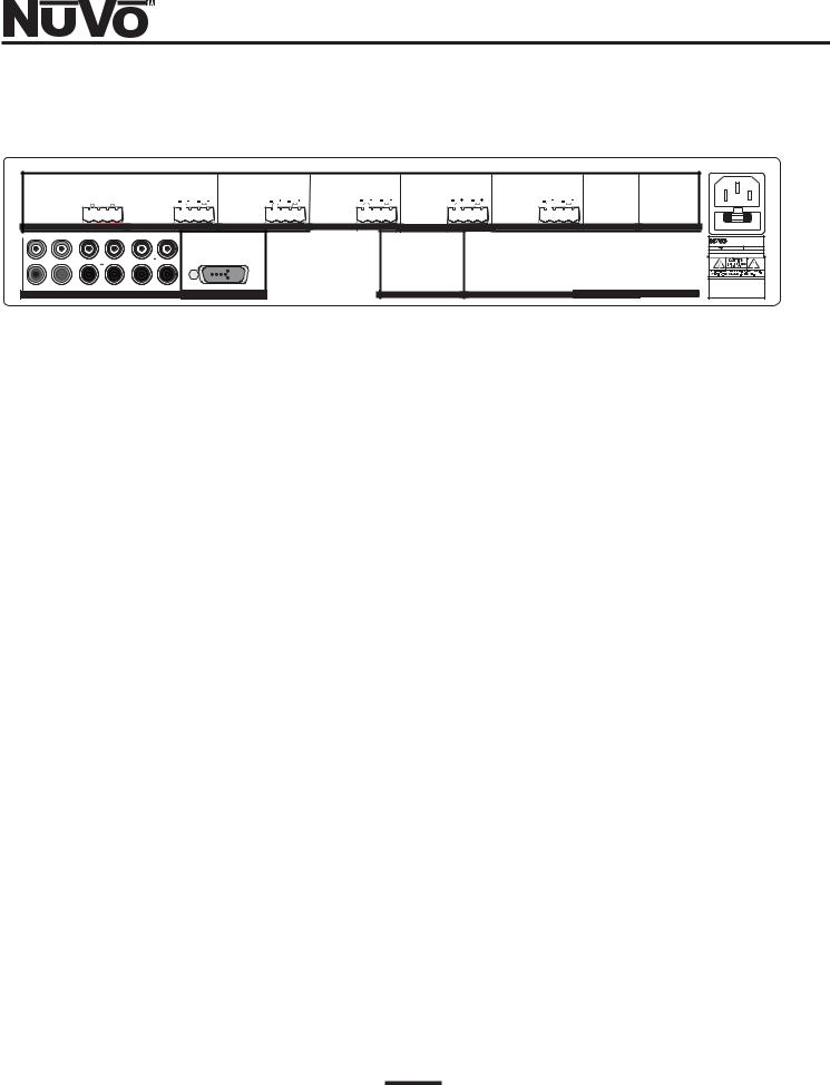
Essentia
Amplifier Back Panel
VARIABLE |
VARIABLE |
VARIABLE |
VARIABLE |
|
VARIABLE |
VARIABLE |
|
OUTPUT |
OUTPUT |
OUTPUT |
OUTPUT |
|
OUTPUT |
OUTPUT |
RS-232 |
OUTPUT POWER |
|
OUTPUT POWER |
OUTPUT POWER |
OUTPUT POWER |
OUTPUT POWER |
OUTPUT POWER |
TIP=L |
20W/6OHM X2 |
TIP=L |
20W/6OHM X2 |
TIP=L |
20W/6OHM X2 |
TIP=L |
20W/6OHM X2 |
TIP=L |
20W/6OHM X2 |
TIP=L |
20W/6OHM X2 |
RING=R |
|
RING=R |
|
RING=R |
|
RING=R |
|
RING=R |
|
RING=R |
|
FIXED |
FIXED |
FIXED |
FIXED |
FIXED |
FIXED |
OUTPUT |
OUTPUT |
OUTPUT |
OUTPUT |
OUTPUT |
OUTPUT |
|
ZONE 1 |
|
|
ZONE 2 |
|
ZONE 3 |
ZONE 4 |
|
ZONE 5 |
|
|
ZONE 6 |
|
|
|
PROGRAM |
1 |
2 |
3 |
4 |
5 |
6 |
CONNECT TO |
|
1 |
3 |
5 |
1 |
3 |
5 |
SUM1 |
SYS ON |
|
|
|
|
|
|
|
1 |
|
|
|
|
|
|
|
CONNECT TO |
CONNECT TO |
|
|
|
|
|
|
|
NV-I8X |
|
|
|
|
|
|
|
|
NV-I8EZP1 |
NV-I8X |
|
|
|
|
|
|
USE NV-SLC1 |
|
|
|
|
|
|
|
|
USE NV-NC1 |
USE NV-SLC1 |
|
|
|
|
|
|
|
|
|
|
|
|
|
|
CABLE |
||
|
|
|
|
|
|
CABLE |
|
|
|
|
|
|
|
|
|
CABLE |
1 |
2 |
3 |
4 |
5 |
6 |
|
5 |
2 |
4 |
6 |
2 |
4 |
6 |
SUM2 |
EXT. MUTE |
|
|
|
|
|
|
|
|
|
|||||||||
|
|
SOURCE INPUTS |
|
|
SOURCE LINK |
|
ZONE TRIGGER OUTPUTS |
|
EMITTER OUTPUTS |
|
SYSTEM NETWORK |
DIGITAL LINK |
||||
1 |
2 |
3 |
4 |
5 |
6 |
7 |
8 |
9 |
10 |
11 |
12 |
13 |
1.Audio Source Inputs: The Essentia amplifier accepts up to six audio sources. A source consists of any
audio component capable of supplying a line level signal.
2Source Link: This multi-pin connection is used to transfer the audio information from the
Essentia main amplifier to the expander amplifier. This output is used along with the Digital Link (11) to expand the system to twelve zones. The source link connection cable is provided with the Essentia D Expander package.
3.Variable Lineout: The variable lineout is intended for zones where additional amplification is needed
and the Essentia keypad is used to control the volume of all the speakers in that zone.
4.Fixed Line Out: The fixed lineout is intended for zones where additional amplification and separate
volume control are needed.
5.Speaker Outputs: Individual stereo speaker outputs for each zone provide 20 watts output per chan-
nel.
6.Zone Triggers: These outputs provide a 12-volt output when the corresponding zone is turned on.
This is used to trigger external equipment specific to a given zone.
7.Emitter Outputs: These outputs transfer IR (infra red) signals, repeated from a zone keypad, from the
Essentia amplifier to the audio source equipment. There are six source specific outputs and two "sum" output that sends IR signals regardless of the selected source.
8.System On: This output provides a constant 12-volt output when any zone is turned on. This is
used to trigger external devices.
9.External Mute: This is designed to mute any audio playing through the system when the phone or
doorbell rings.
10.Network Input: This RJ-45 connection is the input for all zone information coming from the
Essentia keypads. The connection is made using the Network Cable supplied with the package.
11.Digital Link: This multi-pin connection transfers all the digital information from the main ampli-
fier to the expander amplifier. This output is used along with the Source Link (2) to expand the system from six to twelve zones. The Digital Link connection cable is provided with the Essentia D Expander package.
12.RS232 Port: The RS232 serial port allows two-way communication for control by a home automa-
tion system.
13. |
AC: |
A detachable power cord connects the system to an external AC power supply. |
9
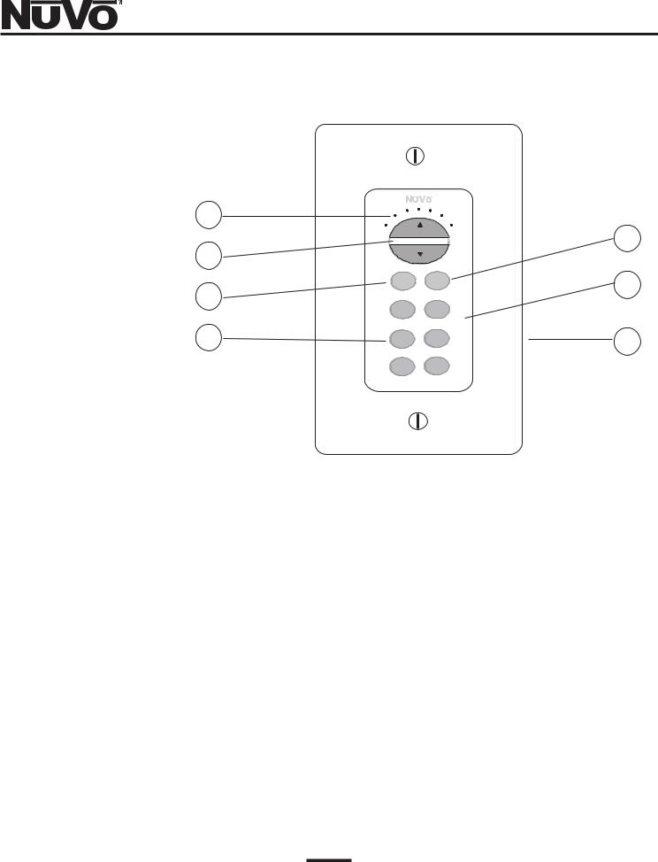
Essentia
Keypad
1
2
3
4
VOLUME
ON |
ALL |
OFF |
OFF |
CD1 |
CD2 |
TNR1 |
TNR2 |
TNR3 |
SAT |
5
6
7
1.Volume Indicator: These LED’s (light emitting diodes) indicate the zones volume level. The lit
LED travels to the right as the volume level is increased and to the left as it is decreased.
2.Volume Buttons: These buttons control the zone’s volume level up and down. They also serve
as the window for receiving IR commands from a remote control.
3.ON/OFF: This turns the individual zone on or off.
4.Source Selectors: These buttons select the desired audio source. Once selected that source but-
ton remains a backlit green until a new source is selected or the zone is turned off. Each keypad ships with 36 preprinted source buttons.
5.ALL OFF: This turns all the zones off simultaneously.
6.Keypad Insert: Each of the Essentia keypads ship with white, ivory and almond color replace-
able Decora style inserts.
7.RJ-45 connection: Each keypad is connected to the Essentia amplifier via a Cat-5 wire and an
RJ-45 connection.
10
 Loading...