


Essentia®
Six-Source, Six-Zone Audio Distribution System
NV-E6GMS, NV-E6GXS
Installation Guide
ENGLISH
IMPORTANT SAFETY INSTRUCTIONS
Danger
Exposure to extremely high noise levels may cause a permanent hearing loss. Individuals vary considerably to noise induced hearing loss but nearly everyone will lose some hearing if exposed to sufficiently intense noise for a sufficient time. The U.S. Government's Occupational Safety and Health Administration (OSHA) has specified the following permissible noise level exposures:
DURATION PER DAY (HOURS) |
8 6 |
4 3 2 1 |
|
|
|
SOUND LEVEL (dB) |
90 93 |
95 97 100 103 |
|
|
|
According to OSHA, any exposure in the above permissible limits could result in some hearing loss. Ear plugs or protectors in the ear canal or over the ears must be worn when operating this amplification system in order to prevent a permanent hearing loss. If exposure in excess of the limits as put forth above, to insure against potentially harmful exposure to high sound pressure levels, it is recommended that all persons exposed to equipment capable of inducing high sound pressure levels, such as this amplification system, be protected by hearing protectors while this unit is in operation.
CAUTION |
RISK OF ELECTRIC SHOCK |
DO NOT OPEN |
CAUTION: TO REDUCE THE RISK OF ELECTRIC SHOCK, DO |
NOT REMOVE CHASSIS. NO USER-SERVICEABLE |
PARTS INSIDE. REFER SERVICING TO QUALIFIED |
SERVICE PERSONNEL. |
AVIS: RISQUE DE CHOC ELECTRIQUE-NE PAS OUVRIR.
THIS SYMBOL IS INTENDED TO ALERT THE USER TO THE PRESENCE OF NON-INSULATED "DANGEROUS VOLTAGE" WITHIN THE PRODUCT'S ENCLOSURE THAT MAY BE OF SUFFICIENT MAGNITUDE TO CONSTITUTE A RISK OF ELECTRIC SHOCK TO PERSONS.
THIS SYMBOL IS INTENDED TO ALERT THE USER TO THE PRESENCE OF IMPORTANT OPERATING AND MAINTENANCE (SERVICING) INSTRUCTIONS IN THE LITERATURE ACCOMPANYING THE UNIT.
APPARATUS SHALL NOT BE EXPOSED TO DRIPPING OR SPLASHING AND THAT NO OBJECTS FILLED WITH LIQUIDS, SUCH AS VASES, SHALL BE PLACED ON THE APPARATUS.
1.Read all safety and operating instructions before using this product.
2.All safety and operating instructions should be kept for future reference.
3.Read and understand all warnings listed on the operating instructions.
4 . Follow all operating instructions to operate this product.
5.This product should not be used near water, i.e. bathtub, sink, swimming pool, wet basement, etc.
6.Only use dry cloth to clean this product.
7.Do not block any ventilation openings, It should not be placed flat against a wall or placed in a built-in enclosure that will impede the flow of cooling air.
8.Do not install this product near any heat sources ; such as, radiators, heat registers, stove or other apparatus (including heat producing amplifiers) that produce heat.
9.Do not defeat the safety purpose of the polarized or groundingtype plug. A polarized plug has two blades with one wider than the other. A grounding-type plug has two blades and a third grounding prong. The wide blade or the third prong are provided for your safety. If the provided plug does not fit into your outlet, consult an electrician for replacement of the obsolete outlet.
10.Protect the power cord being walked on or pinched, particularly at plugs, convenience receptacles and the point where they exit from the apparatus. Do not break the ground pin of the power supply cord.
11 . Only use attachments specified by the manufacturer.
12.Use only with the cart, stand, tripod, bracket, or table specified by the manufacturer or sold with the apparatus. When a cart is used, use caution when moving cart/apparatus combination to avoid injury from tip-over.
13.Unplug this apparatus during lightning storms or when unused for long periods of time.
14.Care should be taken so that objects do not fall and liquids are not spilled into the unit through the ventilation ports or any other openings.
15.Refer all servicing to qualified service personnel. Servicing is required when the apparatus has been damaged in any way; such as, power-supply cord or plug is damaged, liquid has been spilled or objects have fallen into the apparatus, the apparatus has been exposed to rain or moisture, does not operate normally or has been dropped.
16.WARNING: To reduce the risk of fire or electric shock, do not expose this apparatus to rain or moisture.

FRENCH
Danger
L‘exposition a des niveaux eleves de bruit peut provoquer une perte permanente de l’audition, Chaque organisme humain reagit differemment quant a la perte de l’audition, mais quasiment tout le monde subit une diminution de I’acuite auditive lors d’une exposition suffisamment longue au bruit intense. Les autorites competentes en reglementation de bruit ont defini les expositions tolerees aux niveaux de bruits:
DURE EN HEURES PAR JOUR |
8 6 |
4 3 2 |
1 |
|
|
|
|
INIVEAU SONORE CONTINU EN dB |
90 93 |
95 97 100 |
103 |
|
|
|
|
Selon les autorites, toute exposition dans les limites citees ci-dessus, peuvent provoquer certaines pertes d’audition. Des bouchons ou protections dans l’appareil auditif ou sur l’oreille doivent etre portes lors de l’utilisation de ce systeme d’amplification afin de prevenir le risque de perte permanente de l’audition, Dans le cas d’expositions superieures aux limites precitees il est recommande, afin de se premunir contre les expositions aux pressions acoustiquese I evees potentielIement dangeure u ses, aux personnes exposees aux equipements capables de delivrer de telles puissances, tels ce systeme d’amplification en fonctionnement, de proteger l’appareil auditif.
ATTENTION
RISQUE DE CHOC ELECTRIQUE
NE PAS OUVRIR.
ATTENTION: AFIN DE LlMlTER LE RISQUE DE CHO ELECTR/QUE, NE
PAS ENLEVER LE CHASSIS. NE CONTIENT PAS DE
PIECES POUVANT ETRE REPAREE PAR L’UTILISATEUR.
CONFER LE SERVICE APRES-VENTE AUX
REPARATEURS
CE SYMBOLE A POUR BUT D'AVERTIR L'UTILISATEUR DE LA PRESENCE DE VOLTAGE DANGEREUX NON-ISOLE A L'INTERIEUR DE CE PRODUIT QUI PEUT ETRE DE PUISSANCE SUFFISAMMENT IMPORTANTE POUR PROVOQUER UN CHOC ELECTRIQUE AUX PERSONNES.
CE SYMBOLE A POUR BUT D'AVERTIR L'UTILISATEUR DE LA PRESENCE D'INSTRUCTIONS D'UTILISATION ET DE MAINTENANCE DANS LES DOCUMENTS FOURNIS AVEC CE PRODUIT.
AFIN DE REDUIRE LES RISQUÉ D'INCENDIE ET DE DECHARGE ELECTRIQUE, NE PAS EXPOSER CET APPAREIL A LA PLUIE OU A L'HUMIDITE.
IMPORTANTES INSTRUCTIONS DE SECURITE
1.Lire avec attention toutes les recommandations et précautions d'emploi avant d'utiliser ce produit.
2.Toutes les recommandations et précautions d'emploi doivent être conservées afin de pouvoir s'y reporter si nécessaire.
3.Lire et comprendre tous les avertissements énumérés dans les précautions d'emploi.
4.Suivre toutes les précautions d'emploi pour utiliser ce produit.
5.Ce produit ne doit pas être utilisé près d'eau, comme par exemple baignoires, éviers, piscine, sous-sol humides ... Etc.
6.Utiliser exclusivement un chiffon sec pour nettoyer ce produit.
7.Ne bloquér aucune ouverture de ventilation. Ne pas placer le produit tout contre un mur ou dans une enceinte fernée, cela gênerait le flux d'air nécessaire au refroidissement.
8.Ne pas placer le produit près de toute source de chaeur telle que radiateurs, arrivées d'air chaud, fourneaux ou autres appareils générant de la chaleur (incluant les amplificateurs producteurs de chaleur) .
9.Ne pas négliger la sécurité que procure un branchement polarisé ou avec raccordement à la terre, Un branchement polarisé comprend deux fiches dont l'une est plus large que l'autre. Un branchement à la terre comprend deux fiches plus une troisième reliée à la terre. Si la fiche secteur fournie ne s'insert pas dans votre prise de courant. consulter un 'électricien afin de remplacer votre prise obsolète.
10.Protéger le cordon d'alimentation de tout écrasement ou pincement, particulièrement au niveau des fiches, des réceptacles utilisés et à l'endroit de sortie de l'appareil. Ne pas casser la fiche de terre du cordon d'alimentation.
11.Utiliser uniquement les accessoires spécifiés par le constructeur.
12.Utiliser uniquement avec le chariot de transport, le support, le trépied, la console ou la table spécifiés par le constructeur ou vendus avec l'appareil. Lors de l'utilisation d'un chariot, bouger avec précaution l'ensemble chariotlappareil afin d'éviter les dommages d'un renversement.
13Débrancher cet appareil lors d'orages ou s'il n'est pas utilisé pendant une longue période.
14.Des précautions doivent être prises afin qu'aucun objet ne tombe et qu'aucun liquide ne se répande à l'intérieur de l'appareil par les orifics de ventilation ou n'importe quelle autre ouverture.
15.Pour toutes interventions techniques s'adresser à un technicien qualifié.L'intervention technique est nécessaire lorsque l'appareil a été endommagé de n'importe quelle façon, comme par exemple si le cordon secteur ou sa fiche sont détériorés,si du liquide a coulé ou si des objets sont tombés à l'intérieur de l'apparei1,si l'appareil a été exposé à la pluie ou à l'humidité, s'il ne fonctionne pas normalement ou s'il est tombé.
16.ATTENTI0N:Pour réduire le risque d'incendie ou de choc electrique ne pas exposer l'appareil à la pluie ou à l'humidité.

Table of Contents |
|
Introduction |
Page 3 |
Back Panel Features |
Page 4 |
Control Pad Features |
Page 5 |
RC1 Remote Control |
Page 6 |
Installing the Essentia System in Your Home |
|
I. Prewire CAT5 Termination |
Page 7 |
II. Terminating the Speaker Wire |
Page 8 |
III. Installing the Essentia Amplifier |
Page 8 |
IV. Installing the NV-E6GMAP AllPort |
Page 8 |
V. Connecting the Allport to the Essentia Amplifier |
Page 9 |
VI. Attaching Audio Source Equipment |
Page 9 |
Setting up the T2G Tuners, M3 Audio Server and NuVoDock for iPod |
|
for use with NuVoNet |
Page 9 |
VII. Connecting the IR Emitters |
Page 10 |
NuVo T2G Tuner Direct Numeric Access |
Page 10 |
VIII. Expanding Essentia to 16 Zones |
Page 11 |
IX. Using the Essentia Configurator Software |
Page 12 |
1. Main Startup |
Page 12 |
2. IR Libraries |
Page 12 |
3. Defining Sources |
Page 15 |
4. Macros |
Page 16 |
5. Zones |
Page 18 |
6. System Settings |
Page 21 |
7. Update System |
Page 22 |
X. Control Pad Setup |
Page 24 |
XI. Using the Control Pad’s MENU Button |
Page 24 |
Favorites |
Page 24 |
Sources |
Page 25 |
Advanced Zone Control |
Page 25 |
Setup |
Page 26 |
Favorites #1-12 |
Page 26 |
Zone Settings |
Page 26 |
Source Settings |
Page 28 |
System Settings |
Page 28 |
XII. Essentia Accessories |
Page 30 |
The NV-I8DLS Learning Station Interface |
Page 29 |
NV-MI1 Mute Interface Adaptor |
Page 32 |
NV-LSI24 Local Source Interrupt |
Page 33 |
NV-LSA40 Local Source Amplifier |
Page 34 |
NV-LSA40PD Power Distribution Hub |
Page 35 |
NV-P2100 200-Watt Auxiliary Amplifier |
Page 36 |
Specifications |
Page 37 |
Troubleshooting |
Page 38 |
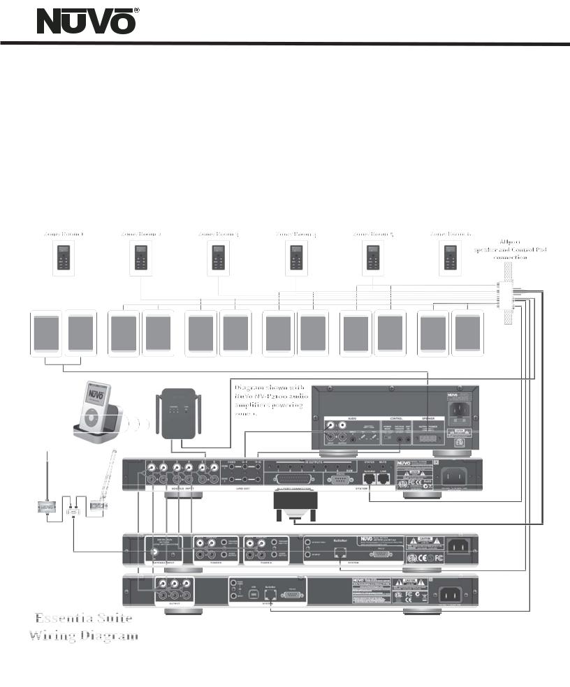
Introduction
Congratulations on the purchase of NuVo's new Essentia System. Essentia provides 40 startlingly clear watts of sound to up to 12 listening zones(12 zones with the addition of the expander). NuVo's Generation D amplification uses the latest in digital technology to provide peak performance in a system that sets a new standard for efficiency and energy conservation. Essentia is the first distributed audio system of its type to bear ENERGY STAR®. This means it consumes less than 1 watt of power in standby mode. Even with all the zones turned on and in full operation, the Essentia System's efficient design sets a new standard in low power consumption.
Essentia truly offers the best in affordable distributed audio for the home. NuVo's state-of-the-art NuVoNet communication through Essentia's award winning Control Pads allows you to interact with your source equipment as if you are standing at your equipment rack. Essentia is a music entertainment system like no other multi-source, multi-zone audio system in its class.
3
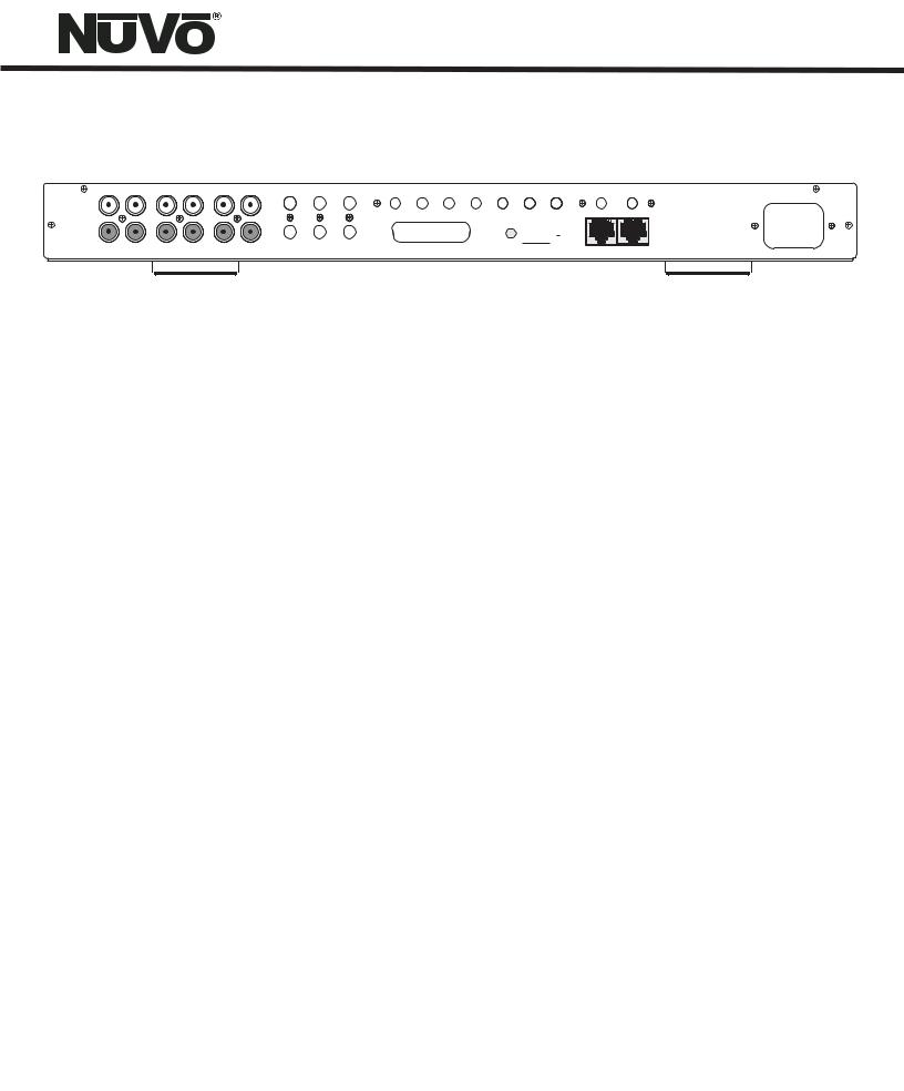
Essentia Back Panel
5 |
6 |
FIXED |
VAR |
TRIG |
IR OUTPUTS |
STATUS MUTE |
ZONE |
|
|
|
|
|
|
|
|
1 |
|
|
|
|
|
|
|
|
1 |
2 |
3 |
4 |
5 |
6 |
SUM |
NuVoNet |
LINK |
|
|
|
|
|
|
|
||
|
|
|
|
|
RS232 |
|
|
|
ZONE |
|
|
|
|
|
|
|
|
2 |
|
|
|
|
|
|
|
|
ALLPORT CONNECTION |
|
|
|
|
|
|
||
|
|
|
|
1807 |
|
MODEL NV-E6GM |
|
|
|
|
SIX SOURCE SIX ZONE |
|
|
|
|
AUDIO DISTRIBUTION SYSTEM |
|
|
|
NuVo Technologies LLC • Hebron, Kentucky USA |
|
|
||
www.nuvotechnologies.com |
|
|
||
|
|
RoHS |
|
|
|
CONFORMS TO UL |
|
|
|
|
STD.60065 CERTIFIED |
|
|
|
3033118 |
TO CAN/CSA STD. |
N1839 |
100~240V |
50~60Hz 130W |
C22.2 No.60065:03 |
MADE IN CHINA |
|||
|
|
|
||
1 |
2 |
3 |
4 |
5 |
6 |
7 |
8 |
9 |
10 |
11 |
12 |
1.Source Inputs: The Essentia will accept up to six audio sources. These are connected to Essentia's main and expander amplifiers with standard stereo RCA cables.
2.Fixed Lineouts: These preamp lineouts are used for sending an audio signal to an external power amplifier. This is useful for large areas that require additional pairs of speakers. These outputs are constant, so an amplifier connected to it will not change volume with that zone's Control Pad. Zones 1 and 2 both have a fixed lineout.
3.Variable Lineouts: These preamp lineouts are also used for sending an audio signal to an external power (needs left justified) amplifier. Use the variable output when you want the volume of the additional amplifier to be controlled by the zone's Control Pad. Like the Fixed Lineouts, zones 1 and 2 each have a variable lineout.
4.Zone Trigger Outputs: These 5-volt outputs are zone - specific voltage triggers for external amplification.
5.Allport Connection: This 25-pin connection consolidates the zone speaker connections to the back of the Allport hub into a single cable connection on the back of the Essentia amplifier.
6. IR emitter Outputs: IR signals received from the Control Pads are passed through the IR outputs to the source equipment using the supplied IR emitters. Outputs 1-6 are routed to the corresponding sources, and the SUM output is common and will pass all IR signals.
7.RS232: The 9-pin RS232 connection is a bi-directional serial port that allows the Essentia System to be controlled by an external home automation device. It is also used for configuration programming download.
8.Status: This is a constant 5-volt output for triggering external equipment. There is no voltage output when the zones are off.
9.NuVoNet: This RJ45 connection is the input for all zone information coming from the Essentia Control Pads and all communication with the NuVoNet Suite source components. This connection is made using the supplied pre-terminated CAT5 or any network CAT5 cable.
10.Link: This RJ45 output is designed to connect to the Link input on the Essentia Expander component and transfers all zone control commands from the Main Unit's NuVoNet or RS232 command input to the Expander for an additional six zones.
11.Mute: This input is designed to temporarily mute any audio playing through the system when the doorbell or phone rings. This works in conjunction with the NuVo NV-MI1 mute interface accessory. It also acts as a trigger for whole house paging through any third party paging device when set for this function in the Configurator Software.
12.AC: A detachable power cord connects the system to an external AC power supply.
4
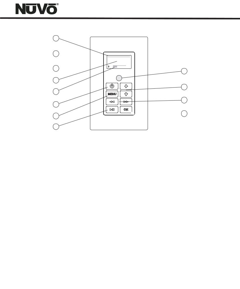
Essentia Control Pad
1
2 
3 
4
5
6
7
8
M3A
2 OF 2-Follow th...
drift-Edge of Tom
1:19 |
3:48 |
12
11
10
 9
9
1.Source Indicator: This indicates the current audio source playing in that zone. Source names can be customized in the Configurator Software with a three-character designation.
2.Wall Plate: Each Control Pad comes with white, ivory, almond, and black trim plates that offer a screwless and elegant, finished installation.
3.OLED Display: The organic light emitting diode display is a highly functional and vivid multi-line display.
4.Now Playing/Menu Display: This portion of the display serves two functions: In normal operation, it indicates the artist, station, metadata, and other source information, and in Menu mode, it displays multiple lines of information for browsing purposes.
5.Volume Level Indicator: This bar graph indicates the audio volume level when the Control Pad is in normal play mode. When in Menu Mode, it indicates the playback status of digital music files from the M3 audio server or iPod.
6.Power: This button turns the local zone on and off and has the ability to turn all zones off simultaneously.
7.Menu: Menu serves as access to music browsing, presets, and favorites, as well as specific zone and system setting parameters.
8.Play/Pause: This IR - programmable button toggles between the play and pause functions of the chosen source. When using the T2G Tuners, this button toggles through the Tuner's receive modes. A third “press and hold” function can also be assigned to this button for additional functionality.
9.OK: The OK button serves a dual function. In normal play mode, it scrolls through the available audio sources. In Menu mode, it is used to select the highlighted menu item.
10.Forward/Reverse: This is an IR - programmable button for simple source transport functions. Typically, it would track forward and back or tune up and down. A third “press and hold” function can also be assigned to this button for additional functionality.
11.Arrow Up and Down: These arrows have a dual function. In normal play mode, they control the volume level up and down. In Menu
mode, they scroll up and down through menu selections.
12.IR Receiver: The Control Pad has a built-in IR receiver for complete wireless control of all the audio source equipment.
5
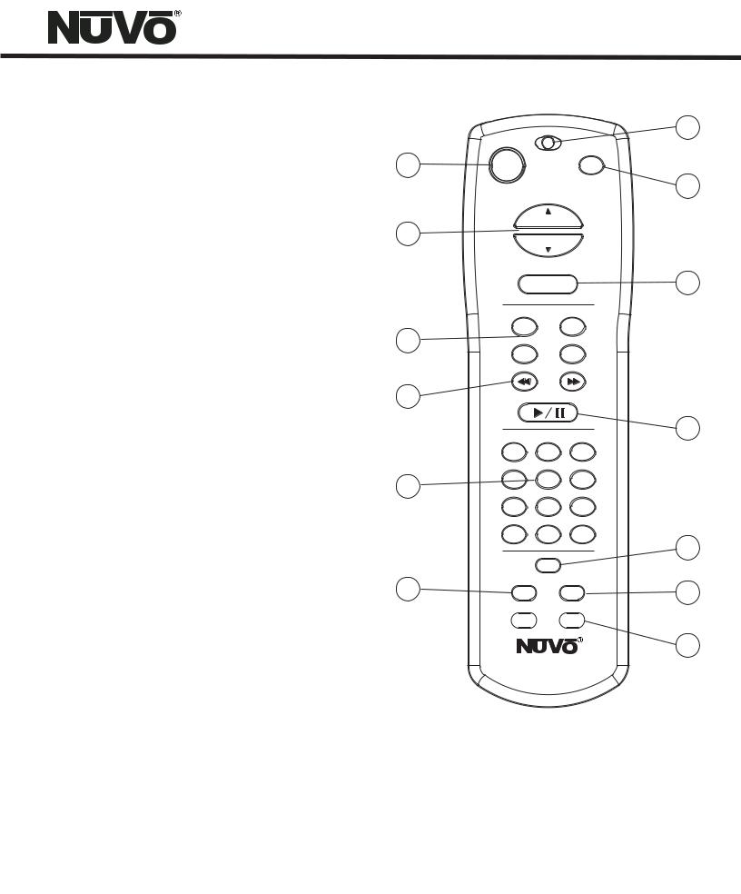
NV-GRC1 Remote Control
1.Power: Each zone can be turned on and off, or all zones can be turned off with this button.
2.Volume: This serves two functions. In normal operation mode, it is a volume control, but when you are using the menu features of the Control Pad, it allows scrolling up and down.
3.Function Buttons: These buttons are currently inactive and designed for future use.
4.Forward and Reverse: These IR programmable buttons are designed for forward and reverse functions.
5.Favorites: A function of the Essentia System is the ability to access user defined favorites for easy access. The first twelve are directly accessible using the GRC1 Favorites buttons.
6.DISP: This button allows access to the Display menu available at each Control Pad.
7.Function LED: This LED (Light Emitting Diode) lights to indicate a button push.
8.MUTE: The GRC1 remote provides a discrete mute function to quickly silence the zone's output.
9.SOURCE/OK: This is another dual function button. In normal playback mode it scrolls through the sources, or in menu mode it selects a highlighted menu choice.
10.Play/Pause: This IR programmable button toggles between the play and pause functions of the chosen source. When using the T2G Tuners, this button toggles through the Tuners’ receive modes.
11.MENU: This button enters the menu features of the Control Pad. When in Menu, mode the Volume up and down buttons scroll through the menu choices.
12.Sleep: This allows access to the sleep timer mode.
13.G1 and G2: These buttons are currently inactive. They are designed for future use.
1
2
3
4
5
6
7
PWR MUTE
HOLD |
8 |
ALL OFF |
|
VOLUME
SOURCE/OK |
9 |
F1 F2
F3 F4
FAVORITES |
10 |
||
|
|||
1 |
2 |
3 |
|
4 |
5 |
6 |
|
7 |
8 |
9 |
|
10 |
11 |
12 |
11 |
|
|
|
|
|
MENU |
|
|
DISP |
|
SLEEP |
12 |
 G1
G1
 G2
G2
13
NV-GRC1
REMOTE CONTROL
6
Installing the Essentia System in Your Home
I. Prewire
The Essentia System uses CAT5 cable for Control Pad control and either two or four-conductor 16-gauge speaker wire. All the wire is “homerun” from each zone to the location of the Essentia amplifier and Audio Source equipment.
Complete CAT5 Crimping Instructions
The NuVo audio systems require CAT5, unshielded, twisted pair (UTP) for communication between the Control Pads and the main amplifier unit. Each end of the wire is terminated with an RJ45 connector.
The Essentia System can accommodate 2,000 total feet of CAT5 cable. For the most reliable operation, it is best that no single run of CAT5 exceeds 250 feet.
Top view with tab down.
|
|
Bus |
|
- |
Bus+ |
|
|
Data |
|
Data |
|
||
|
|
|
|
Power |
||
IR |
ActiveGround Control Control |
IR |
Data Ground +20V |
|
||
1 2 3 4 5 6 7 8 |
|
|||||
Pair 2 |
Pair 1 |
Pair 4 |
|
Pair 3 |
|
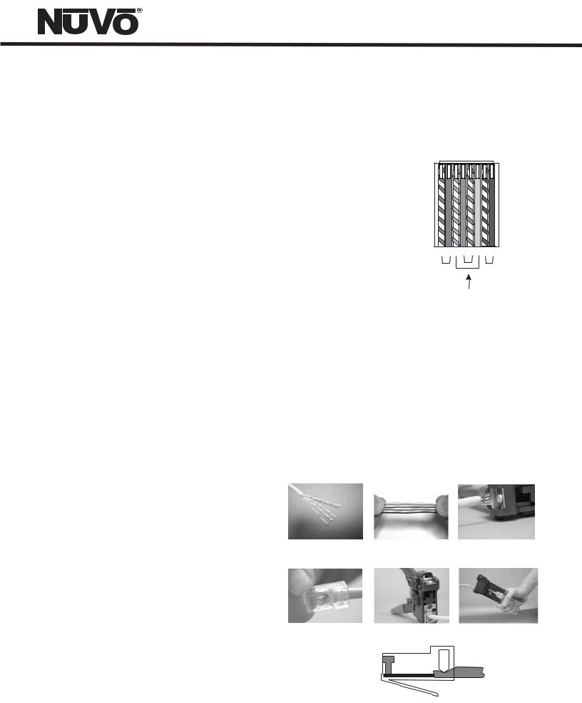
The correct wiring scheme for the CAT5 cable is standard EIA/TIA 568A, or 568B. Properly terminating the CAT5 cable is crucial for the operation of the system. It is very important to use a good quality crimp tool, and test each end to end run with a CAT5 wire tester to insure that your system operates flawlessly, Fig.1.
Step-by-Step Crimping Instructions:
1.Strip a 2 to 3 inch portion of the insulation, exposing the 4 twisted pairs.
2.Untwist the wires and fan them out individually. Arrange the wires into the correct color scheme as shown in Fig. 1.
3.Flatten the wires in their correct order and trim them evenly across the top. Most crimp tools have a wire trimmer built-in. It is best to trim the wires to about ½” in length.
4.While holding the wires flat between your thumb and forefinger, insert the wires into the RJ45 connector so each is in its own slot. Push the wire into the RJ45 so all 8 conductors touch the end of the connector. The insulation jacket should extend beyond the crimp point of the RJ45.
5.Insert the RJ45 into the crimp tool receptacle and squeeze the tool firmly. Note that a ratchet type tool should tighten down until it no longer clicks.
6.The RJ45 should be firmly crimped to the CAT5 insulation. It is necessary that the color scheme be repeated identically on each end of the wire.
7.Test each termination with a CAT5 Tester before completing the installation.
Wires insert from this end.
Fig. 1: EIA 568A and 568B wiring scheme for CAT5 Cable
Pin # 568A |
Pin # 568B |
||
1. Green Stripe |
1. Orange Stripe |
||
2. |
Green |
2. |
Orange |
3. |
Orange Stripe |
3. |
Green Stripe |
4. Blue |
4. Blue |
||
5. |
Blue Stripe |
5. |
Blue Stripe |
6. Orange |
6. Green |
||
7. |
Brown Stripe |
7. |
Brown Stripe |
8. Brown |
8. Brown |
||
Note: Colors listed as “stripe” are a white wire with a colored stripe.
Step 1 |
Step 2 |
Step 3 |
Step 4 |
Step 5 |
Step 6 |
7
II. Terminating the Speaker Wire (Fig. 2)
All NuVo Systems operate across a “homerun” wiring scheme using CAT5 for the zone's Control Pad communication and control, and a separate run of speaker wire for each zone. The Essentia operates differently in that its zone speaker wire termination is made at the Allport hub. The suggested wire for this purpose is 16-gauge, 2- or 4- conductor speaker wire rated for in-wall use.
The termination is performed using a modular “Euro” connector. Each conductor is screwed down to the Euro connector and plugged into the appropriate zone speaker connection on the back of the Allport. The proper termination for each zone is Left channel: — and +, and Right channel: — and +.
III. Installing the Essentia Amplifier
System setup works best when the amplifier is placed in the same location as the audio source equipment. This is typically in an audio rack, entertainment center, or a closet dedicated to housing the home audio/video equipment. To insure cool, reliable operation, we highly recommend allowing one empty rack space above a Main or an Expander amplifier unit. Also, insure there is ventilation around the whole rack location.
The amplifier should be plugged in and the blue Standby LED should be lit before proceeding with the remaining installation. This activates protective circuitry for the internal components.
IV. Installing the NV-E6GMAP-DC Allport (Fig. 3)
The Allport is a multi-connection hub designed to accept all the CAT5 and speaker wires from all zones of the Essentia System. The location of the Allport should be determined by the location of the Essentia amplifier. It is best to place it in a wall behind the amplifier that can be easily accessible if necessary.
The Allport is designed to fit into most any dual-gang mounting ring, and has two sets of terminations on the backside. Eight RJ45 jacks are meant for the Control Pads in up to six zones, with one reserved for an additional Control Pad and another for a “link” jack used for expansion from six to twelve zones.
IThe order in which the CAT5 cables are plugged into the jacks is irrelevant to the system's operation. Six modular “Euro” connectors are used to terminate the speakers in each zone, see Section II, Terminating the Speaker Wire.
Once the speaker and CAT5 terminations are complete, the Allport can be installed.
Fig. 2
|
|
|
|
|
|
+ |
+ |
||||
|
|
|
|
|
|
|
|
|
|
|
|
|
|
|
|
|
|
|
|
|
|
|
|
|
|
|
|
|
|
|
|
|
|
|
|
|
|
|
|
|
|
|
|
|
|
|
|
LEFT LEFT RIGHT RIGHT
- + - +
Fig. 3
+ |
|
+ |
+ |
|
+ |
+ |
|
+ |
+ |
|
|
+ |
+ |
|
|
+ |
|
|
+ |
|
+ |
8
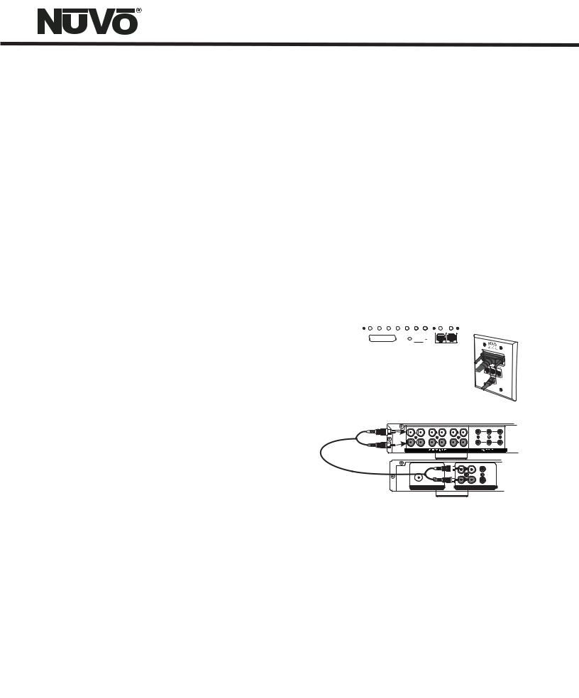
V. Connecting the Allport to the Essentia Amplifier (Fig. 4)
Once installed, the front of the Allport has three “Device” RJ45 jacks for CAT5 connections from the NuVoNet Suite components, and an RJ45 jack labeled “NuVoNet” which must be connected to the “NuVoNet” input on the back of the Essentia amplifier. This is necessary for Control Pad communication, regardless the use of the NuVoNet Suite components. Once connected, the Control Pads are ready to communicate with the System. The Essentia System is shipped with a six-foot pre-terminated CAT5 network cable, or you can purchase one if a different length is required.
The speaker connection is made with the 25-pin Allport Cable. The modular speaker connectors must be plugged into the appropriate speaker connections on the back of the Allport.
VI. Attaching Audio Source Equipment (Fig. 5)
Each piece of audio equipment is connected to the Essentia amplifier with standard stereo RCA cables. Attach an RCA cable to the corresponding audio output on the source equipment and to the desired source input on the back of the Essentia amplifier. The numbered input for each source is important in the configuration of the system. This will be covered in detail in the Essentia Configurator portion of this manual.
Using the Fixed and Variable Lineouts
The Zone 1 and 2 outputs have 3.5mm stereo pre-amp lineouts attached to them. Their purpose is to provide the zone’s current audio selection signal to an additional amplifier. Both versions, fixed (a constant signal that requires a volume control separate from the NuVo zone Control Pad) and variable (a signal that varies in level relative to the volume setting on the NuVo zone Control Pad) are both simultaneously active and require no external switch for use.
Each output has an attached voltage trigger output that allows the attached amplifier to be triggered from a voltage presented when the zone Control Pad is turned on. The voltage trigger is removed when the zone is truned off.
Setting up NuVo Sources for use with NuVoNet
A feature of the Essentia System is its ability to automatically communicate with the T2G family of tuners, the M3 Audio Server, and the Wired and Wireless NuVoDocks for iPod. The communication happens through the Allport connection hub across a communication protocol called NuVoNet. Although software programming is not necessary for this function, configuring the installation through the Configurator Software prior to installation has distinct advantages, see X. Essentia Configurator Software.
When the T2G tuners or M3 Server are plugged in for the first time, they will display a prompt to select a source input number for the Essentia. For NuVoNet to communicate properly, you should have already connected the NuVoNet components to one of the three “Peripheral Device” inputs on the face of the Allport.
Fig. 4
IR OUTPUTS |
|
STATUS MUTE |
1 |
2 |
3 |
4 |
5 |
6 |
SUM |
NuVoNet |
LINK |
|
|
|
|
|
RS232 |
|
|
|
ALLPORT CONNECTION
Fig. 5
7 |
8 |
9 |
10 |
11 |
12 |
FIXED |
VAR |
TRIG |
|
|
|
|
|
|
ZONE |
|
|
|
|
|
|
|
|
7 |
|
|
|
|
|
|
|
|
ZONE |
|
|
|
|
|
|
|
|
8 |
|
|
|
|
|
|
|
AUX IN AUDIO OUT |
|
|
|
|
USE ONLY NuVo |
|
|
|
|
|
|
|
|
|
NV-T2PAS |
|
|
L |
|
TRIGGER |
|
|
POWERED ANTENNA SYSTEM |
|
|
|
|
ON=+12V |
|
|
|
|
|
|
|
R |
|
AUDIO |
|
|
|
|
|
|
|
|
OUTPUT |
|
|
IN |
|
|
|
|
|
|
|
|
ANTENNA INPUT |
|
|
|
TUNER B |
|
|
|
T2G AM/FM and XM Tuners
Each of the T2G Tuner components houses two individual AM/FM or Satellite receivers, which have their own display on the front panel. Once the T2G is plugged in and the NuVoNet CAT5 is connected to the Allport, the initial display, OPERATING MODE will appear for each tuner. Below this, the choices are STAND ALONE, SOURCE 6, SOURCE 5, SOURCE 4, SOURCE 3, SOURCE 2, and SOURCE 1. Stand Alone is automatically highlighted at initial startup. Selecting the appropriate Essentia source input is accomplished by turning the Select knob for each tuner counter-clockwise until the desired source input number is highlighted. It is selected by pushing the Select knob. Once this is complete, the Essentia System NuVoNet will recognize that source.
9
M3 Audio Server and T2SIR Dual Sirius Ready Tuners
At initial startup, the front panel display will display a prompt screen Status, all outputs. Below this header are three lines of text representing each of the three audio outputs labeled A, B, and C. Output A will be highlighted and it will display OUTPUT A: PRESS OK TO SELECT NUVONET SOURCE. When OK is selected, the top line of the display will read Address, Output A, below this, STANDALONE will be highlighted and the other choices will be SOURCE 1, SOURCE 2. . . and as you scroll using the down arrow, SOURCE 3, SOURCE 4, SOURCE 5, and SOURCE 6 will appear. Highlight the appropriate choice and press OK to select. This will set the first channel music output. You will then be prompted to repeat these steps for the remaining two channels.
NuVoDock for iPod
Both the Wired and Wireless NuVoDocks for iPod use a simple rotary switch to set the appropriate source input. Up to two Wireless NuVoDocks and six Wired NuVoDocks could be used as individual sources through NuVoNet. The Wired and Wireless NuVoDocks consist of a dock for iPod playback and recharging as well as a receiver component designed to communicate with NuVoNet. Prior to plugging the receiver into the Essentia Allport, set the Source rotary switch to the desired source number input. Once set, theEssentia Control Pads will automatically display the iPod information when an iPod is plugged into the NuVoDock. Each NuVoDock and receiver must have a separate source number selected.
Note that although the NuVoDock system has a 16 position rotary switch for source input, only positions 1 – 6 are used.
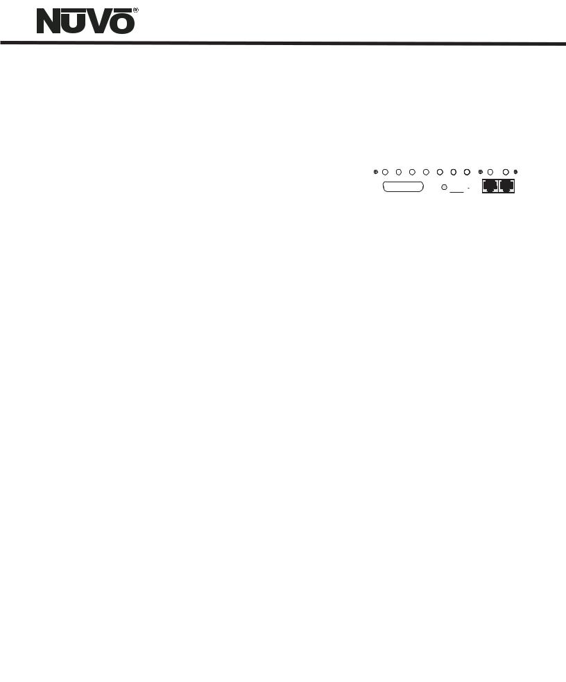
VII. Connecting the IR Emitters for Third-Party Source Components (Fig. 6)
IR commands for the source equipment are transferred from the Essentia amplifier to the source equipment using the mini IR mouse emitters. Six of these are supplied with your Essentia System. The emitter is plugged into the corresponding source IR output on the Essentia and then placed over the IR receiver window on the source component. The IR outputs are individually routed to sources 1-6.
The two SUM outputs will flash any IR command that is sent from any of the zones. This is most commonly used with an IR blaster designed to flash IR commands to a variety of components.
Fig. 6
|
|
|
IR OUTPUTS |
|
|
|
STATUS |
MUTE |
1 |
2 |
3 |
4 |
5 |
6 |
SUM |
NuVoNet |
LINK |
|
|
|
|
|
RS232 |
|
|
|
ALLPORT CONNECTION
COMPACT
dISC
NuVo T2G Tuner Direct Numeric Access (Fig. 7)
The NuVo T2G Tuners have the ability for direct IR access to numeric station tuning. This can be done through the T2G remote control or using a third party remote control that has been taught the T2G IR codes. To allow this control, it is necessary to link the Essentia SUM IR output to the Direct IR input on the T2G using a stereo 3.5mm (1/8”) mono patch cable. Once the connection is made, the T2G will respond to the numeric IR commands issued through the Essentia Control Pad IR receivers.
Fig. 7
T2G Tuner IR Input
|
|
|
|
Model NV-T2DF |
|
NuVoNet |
|
|
Dual XM Tuner |
||
NuVo Techonlogies LLC•Cincinnati Ohio USA |
|||||
IR PASS-THRU |
|
||||
IN |
OUT |
www.nuvotechnologies.com |
|||
RS232
IR INPUT
SYSTEM
Essentia IR Ouput |
|
|
|
|
||||
|
|
|
IR OUTPUTS |
|
|
|
STATUS |
MUTE |
1 |
2 |
3 |
4 |
5 |
6 |
SUM |
NuVoNet |
LINK |
|
|
|
|
|
RS232 |
|
|
|
ALLPORT CONNECTION
10

VII. Expanding Essentia to 12 Zones (Fig. 8)
Six additional listening zones can be added to the Essentia System using the Essentia Expander System, NV-E6GXS. The expander requires the use of the Link RJ45 connection on the main amplifier. This is connected to the corresponding Link RJ45 connection on the expander amplifier. All of the upper zone control commands from the main unit's NuVoNet or RS232 command input are transferred through this connection. The NV-RCA3 Y-adapter cables included with the expander unit allow a parallel connection of the left and right source output to the corresponding source inputs on both amplifier units, fig. 8a.
The expansion requires the installation of the expander Allport included with the expander system. The expander Allport is the connection for the additional zone Control Pads, up to seven, and the additional zone speakers. A second Allport cable must be attached from the expander Allport to the expander amplifier and a short CAT5 jumper cable, included with the expander system is used on the back of the two Allports to integrate all of the System’s Control Pads into one NuVoNet connection to the main amplifier, Fig. 8b.
Fig. 8c
Once these connections are complete, the Control Pads can be addressed for a twelve-zone system.
Note: If you are using the Remote (wired) or Wireless versions of the NuVoDocks for iPod, it is necessary to use a female to male adaptor. These are readily available and are not supplied with the NuVoDock system, fig. 8c.
Fig. 8a |
Essentia G Expander |
1 2 3 4 5 6 |
FIXED VAR TRIG |
|
ZONE |
|
7 |
|
ZONE |
|
8 |
Essentia G Main
1 2 3 4 5 6 FIXED VAR TRIG
ZONE 1
ZONE 2
|
Audio Source |
|
AUDIO OUT |
USE ONLY NuVo |
|
NV-T2PAS |
TRIGGER |
POWERED ANTENNA SYSTEM |
ON=+12V |
|
AUDIO |
|
OUTPUT |
IN |
|
ANTENNA INPUT |
TUNER B |
NV-RCAY3 “Y” cable
Fig. 8b
+
+ |
+ |
+ |
+ |
+
E6GXAP-DC
Expander Allport Hub

 +
+ 
 +
+ 
 +
+ 


 +
+  +
+ 


+

 +
+ 
+ 
 +
+ 
+
+ |
+
E6GMAP-DC
Main Allport Hub

 +
+ 
 +
+ 
 +
+ 
 +
+ 

 +
+ 
 +
+ 
Fig. 8
ALLPORT CONNECTION |
11 |
 Loading...