


®
INSTALLATION INSTRUCTIONS
READ & SAVE THESE INSTRUCTIONS!
QuieTTest® Twin Blower Ventilator
MODELS: QT130, QT200 & QT300
For Ceiling Installation
IMPORTANT SAFETY INSTRUCTIONS |
POWER |
|
|
UNIT |
|
WARNING: TO REDUCE THE RISK OF FIRE. ELECTRIC |
||
|
||
SHOCK, OR INJURY TO PERSONS, OBSERVE THE |
|
|
FOLLOWING: |
|
|
A. Use this unit only in the manner intended by the manufacturer. |
|
|
If you have questions, contact the manufacturer. |
HANGER |
|
B. Before servicing or cleaning unit, switch power off at service |
||
panel and lock service panel to prevent power from being |
ROD |
|
switched on accidentally. |
|
|
When the service disconnecting means cannot be locked, securely |
|
|
fasten a prominent warning device, such as a tag, to the service |
|
|
panel. |
|
|
CAUTION: |
|
|
For general ventilating use only. Do not use to exhaust hazardous |
|
|
or explosive materials and vapors. |
|
|
INSTALLATION INSTRUCTIONS |
|
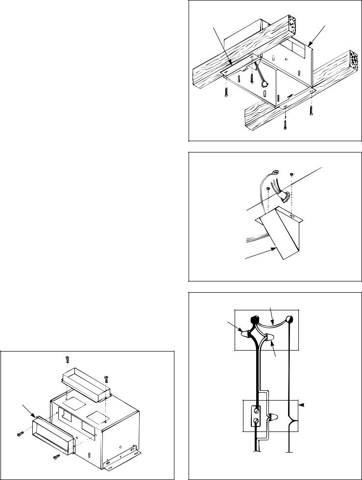
POWER
CONNECTOR
SLOTS
WING NUT, HANGER ROD
FIGURE 1
WARNING: TO REDUCE THE RISK OF FIRE, ELECTRIC SHOCK, OR INJURY TO PERSONS, OBSERVE THE FOLLOWING:
A.Installation work and electrical wiring must be done by qualified person(s) in accordance with all applicable codes and standards, including fire-rated construction.
B.Sufficient air is needed for proper combustion and exhausting of gases through the flue (chimney) of fuel burning equipment to prevent back drafting. Follow the heating equipment manufacturer's guideline and safety standards such as those published by the National Fire Protection Association (NFPA), and the American Society for Heating, Refrigeration and Air Conditioning Engineers (ASHRAE), and the local code authorities.
C.When cutting or drilling into wall or ceiling, do not damage electrical wiring and other hidden utilities.
D.Ducted fans must always be vented to the outdoors.
E.If this unit is to be installed over a tub or shower, it must be marked as appropriate for the application.
F.NEVER place a switch where it can be reached from a tub or shower.
•Suitable for use with solid state speed controls.
•Uses standard 31⁄4" x 10" ducting.
•Designed for ceiling installation.
•Do not mount over bathtub or shower stall enclosure.
•Not for use in kitchens.
•The ventilator consists of the housing, mounting brackets, junction box, power unit/blower assembly, damper section and grille assembly.
FAN MUST NOT BE INSTALLED IN A CEILING THERMALLY INSULATED TO A VALUE GREATER THAN R-40.
FOR BEST RESULTS
When installing the ventilator in a new construction site, install the housing during the rough-in construction of the building. The power unit and grille should be installed after the finished ceiling is in place. To install the ventilator in an existing building, an accessible area
(attic or crawl space) is required from above the planned location.
ROOF CAP
VERTICAL
DISCHARGE
31⁄4" x 10"
DUCT
WALL CAP
KNOCKOUTS
FAN
HOUSING
HORIZONTAL
DISCHARGE
FIGURE 2
INSTALLATION IN
A NEW CONSTRUCTION SITE
PREPARATION
CAUTION: When handling the power unit do not reach in the end openings and bend the blower wheels.
Refer to Figure 1.
1.Remove power unit from housing assembly.
(a)If necessary, unplug power plug from the connector.
(b)Loosen wing nut on hanger rods that hold the power unit.
(c)Unfasten hanger rods from slots and remove power unit.
(d)Set power unit aside until needed.
2.Refer to Figure 2. Remove one of the wiring knockouts from the housing.
3.The ventilators can be ducted for either vertical or horizontal discharge.
4.Refer to Figure 3. Mount 31⁄4" x 10" damper section on top of housing for vertical discharge or on the side of housing for horizontal discharge with two (2) screws furnished.
MOUNTING THE HOUSING
NOTE: These ventilators are designed for installation between 16" O.C. ceiling joists with no framing necessary. If the building structure has 24" O.C. joists construction, framing will be required.
1.Position housing between ceiling joists and adjust height
to finished ceiling. Loosen two (2) hex nuts for each mounting
bracket from inside the housing and make the adjustment. Tighten the four (4) hex nuts.
NOTE: There are four (4) additional mounting slots in the housing for mounting or relocating the mounting brackets.
2.Refer to Figure 4. Screw housing to joists using holes in mounting brackets and four (4) screws furnished.
3.Install standard 31⁄4" x 10" ductwork from damper section
to outside wall or through roof and mount appropriate wall or roof cap (optional.) Refer to the instructions provided with the caps.
IMPORTANT: Be certain there are not any obstructions at the discharge of the ventilator. Be certain insulation does not get into the ductwork or into the blower.
WIRING
NOTE: All wiring connections must comply with local codes, ordinances and the National Electrical Code and the ventilator must be properly grounded. Disconnect power at circuit breaker before making wire connections.
1.Refer to Figure 5. Loosen screws and remove junction box.
2.Run 120vAC supply wiring with ground through switch box to knockout in ventilator housing and secure with box connector.
3.Refer to Figure 6. Connect supply wires to ventilator wires: black to black, white to white. Connect ground wire to green ground screw.
4.Replace junction box and tighten screws.
5.Connect supply wire to switch. NOTE: Switch must be purchased separately. Refer to NuTone's catalog.
POWER UNIT INSTALLATION
1.Refer to Figure 7. The power unit mounts with two hanger rods to the mounting brackets. Insert the hanger rods through the holes in the mounting bracket hooking them from the inside
to the outside.
2.Position the power unit so that its discharge opening is in line with the installed ductwork. Hold the power unit in position between the mounting brackets and swing the hanger rods
into the slots on the power unit and securely tighten the wing nuts.
3.Plug the three (3) wire connectors from the junction box
into the wire receptacle connector from the power unit making sure the plug is properly aligned.
VERTICAL DISCHARGE
31⁄4" x 10" DAMPER SECTION
31⁄4" x 10" DAMPER SECTION
HORIZONTAL
DISCHARGE
FIGURE 3
MOUNTING |
VENTILATOR |
BRACKET |
HOUSING |
|
FIGURE 4 |
JUNCTION
BOX
FIGURE 5
GREEN
GREEN
BLACK 

 GROUND
SCREW
WHITE
STANDARD |
|
SWITCH |
WALL SWITCH |
|
BOX |
EARTH 120vAC, 60 Hz  GROUND HOUSE POWER
FIGURE 6

GRILLE INSTALLATION
1.Refer to Figure 8. Compress grille mounting springs and insert into slots in the housing.
2.Press grille firmly into place against ceiling.
MAINTENANCE
•WARNING: Risk of fire or electrical shock; disconnect the power before cleaning or performing any maintenance on the ventilator.
•If the grille becomes soiled, use only a mild soap and water solution for cleaning. Do not use solvents or abrasive cleaners.
INSTALLATION IN
EXISTING CONSTRUCTION
Installing a ventilator in an existing construction site requires at least a small accessible area (attic or crawl space) above the planned installation location.
Review “INSTALLATION IN A NEW CONSTRUCTION SITE” and follow all instructions which apply to your installation.
Locate the ventilator next to a ceiling joist.
Plan the ductwork and wiring before proceeding with the installation.
CAUTION: Check the area above the planned installation to be certain that:
1.Ductwork can be installed or that the area is sufficient for proper mounting.
2.Wiring can be run to the planned location.
3.No wiring or other obstruction will interfere with the installation.
INSTALLATION FROM ACCESSIBLE AREA ABOVE (using headers)
1.From below the installation site, drill a small hole in ceiling at the planned location.
2.Locate hole in attic or crawl space.
3.In attic or crawl space, mark ceiling for cutout by using the housing as a template. Cutout dimensions: 103⁄16" x 141⁄2". The short side (103⁄16") of the cutout must be right next to the ceiling joist.
4.Refer to Figure 9. Mark cutout along marked line.
NOTE: If ceiling is plaster, cutout should be made from below to avoid chipping plaster.
5.Install headers between joists using nails or screws leaving 103⁄16" between them.
6.Install brackets upside down on housing's long dimension using hex nuts.
7.Mount damper section to housing, install housing and connect wiring and ductwork. Install power unit/blower assembly and grille.
|
MOUNTING |
|
BRACKET |
|
HOOK HANGER |
|
RODS FROM INSIDE |
|
TO OUTSIDE |
|
HANGER ROD |
HANGER |
|
ROD |
|
SLOT |
POWER UNIT |
|
FIGURE 7 |
SPRING |
MOUNTING |
|
MOUNTING |
||
SPRING |
||
CLIP |
||
|
FIGURE 8
MOUNTING |
BRACKET |
HEADER |
HEADER |
FIGURE 9 |
 Loading...