


ACS30BC
MODEL ACS30
CONVERTIBLE RANGE HOOD
CAMPANA EXTRACTORA
CONVERTIBLE DE MODELO ACS30
READ AND SAVE
THESE INSTRUCTIONS
INTENDED FOR DOMESTIC
COOKING ONLY.
For Non-ducted Installation:
a) Purchase non-ducted filter separately. (Model 41F)
b) Remove and discard damper/duct connector and louver
cover (See Step 2) in “Prepare the Hood,” Page 2.
c) Follow all steps except steps inside dotted lines.
For Ducted Installation:
Follow all steps, including steps inside dotted lines.
WARNING
TO REDUCE THE RISK OF FIRE, ELECTRIC SHOCK,
OR INJURY TO PERSONS, OBSERVE THE FOLLOWING:
1. Use this unit only in the manner intended by the manufacturer. If you have questions, contact the manufacturer
at the address or telephone number listed in the warranty.
2. Before servicing or cleaning unit, switch power off at
service panel and lock the service disconnecting means
to prevent power from being switched on accidentally.
When the service disconnecting means cannot be
locked, securely fasten a prominent warning device,
such as a tag, to the service panel.
3. Installation work and electrical wiring must be done by
a qualified person(s) in accordance with all applicable
codes and standards, including fire-rated construction
codes and standards.
4. Sufficient air is needed for proper combustion and
exhausting of gases through the flue (chimney) of fuel
burning equipment to prevent backdrafting. Follow the
heating equipment manufacturer’s guideline and safety
standards such as those published by the National
Fire Protection Association (NFPA), and the American
Society for Heating, Refrigeration and Air Conditioning
Engineers (ASHRAE), and the local code authorities.
5. When cutting or drilling into wall or ceiling, do not damage electrical wiring and other hidden utilities.
6. Ducted fans must always be vented to the outdoors.
7. Do not use this unit with an additonal speed control
device.
8. To reduce the risk of fire, use only metal ductwork.
9. Use with approved cord-connection kit only.
10 This unit must be grounded.
TO REDUCE THE RISK OF A RANGE TOP GREASE FIRE:
1. Never leave surface units unattended at high settings.
Boilovers cause smoking and greasy spillovers that
may ignite. Heat oils slowly on low or medium settings.
2. Always turn hood ON when cooking at high heat or
when cooking flaming foods.
3. Clean ventilating fans frequently. Grease should not be
allowed to accumulate on fan or filter.
4. Use proper pan size. Always use cookware appropriate
for the size of the surface element.
TO REDUCE THE RISK OF INJURY TO PERSONS IN THE
EVENT OF A RANGE TOP GREASE FIRE, OBSERVE
THE FOLLOWING:*
1. SMOTHER FLAMES with a close-fitting lid, cookie
sheet, or metal tray, then turn off the burner. BE CAREFUL TO PREVENT BURNS. If the flames do not go
out immediately, EVACUATE AND CALL THE FIRE
DEPARTMENT.
2. NEVER PICK UP A FLAMING PAN - You may be
burned.
3. DO NOT USE WATER, including wet dishcloths or
towels - a violent steam explosion will result.
4. Use an extinguisher ONLY if:
A. You know you have a Class ABC extinguisher and
you already know how to operate it.
B. The fire is small and contained in the area where
it started.
C. The fire department is being called.
D. You can fight the fire with your back to an exit.
* Based on “Kitchen Fire Safety Tips” published by
NFPA.
IMPORTANT
Para instalación sin ducto:
Para instalación con ducto:
PRECAUCION
PARA REDUCIR EL RIESGO DE INCENDIO, CHOQUE ELECTRICO, O LESION A PERSONAS, PROCURE LO SIGUIENTE:
PARA REDUCIR EL RIESGO DE INCENDIO DEBIDO A GRASA
ACUMULADA EN LAS HORNILLAS:
PARA REDUCIR EL RIESGO DE LESION A PERSONAS RE-
INSTALLER: Leave This Manual With The
Homeowner. HOMEOWNER: Use and Care
Information on Page 5.
INSTALADOR: Deje este manual con el
dueño de la casa. DUEÑO DE LA CASA:
Información acerca del uso y los cuidados
en la Página 5.
Register your product online at:
www.nutone.com/register
Registre su producto en línea
en: www.nutone.com/register
SULTADO DE UN INCENDIO DEBIDO A GRASA ACUMULADA
EN LAS HORNILLAS, PROCURE LO SIGUIENTE:*
LEA Y CONSERVE
ESTAS INSTRUCCIONES
PREVISTO PARA COCINAR
DOMÉSTICO SOLAMENTE.
IMPORTANTE
a) Compra el filtro sin conductos separado. (Modelo 41F)
b) Quite y descarte el conector del regulador/ducto y la
tapa de la rejilla (Véase paso 2) en la Página 2 titulada
“Prepare el extractor.”
c) Siga todos los pasos excepto de los pasos dentro las
líneas suspensivas.
Siga todos los pasos incluyendo los pasos dentro de las
líneas suspensivas.
1. Utilice esta unidad sólo en la manera prescrita por el
fabricante. Si tiene usted alguna pregunta, comuníquese
con el fabricante a la dirección o el teléfono indicados en la
garantía.
2. Antes de limpiar o de poner en servicio la unidad, apague
el interruptor en el panel de servicio, y asegure el panel
de servicio para evitar que se encienda accidentalmente.
Cuando el dispositivo para desconectar el servicio
eléctrico no puede ser cerrado con algún tipo de traba,
sujete fuertemente al panel de servicio, una etiqueta de
advertencia prominente.
3. Todo trabajo de instalación y cableado eléctrico debe ser
realizado por personal calificado y de acuerdo con todos
los códigos y normas pertinentes, incluyendo los códigos
y normas relacionados con construcción clasificada para
incendio.
4. Aire suficiente es necesario para facilitar la combustión
adecuada y la salida apropiada de gases por la chimenea
de la unidad y para evitar corrientes de aire invertidas. Siga
las instrucciones y medidas de seguridad del fabricante del
equipo y de las sociedades profesionales de equipos de
calentadores y los reglamentos de seguridad locales.
5. A cortar o perforar la pared o el techo, no dañe el cableado
eléctrico u otros servicios públicos ocultos a la vista.
6. Los abanicos con ducto deberán siempre tener una salida
hacia el exterior.
7. No utilice esta unidad en conjunto con cualquier dispositivo
de control de velocidad adicional.
8. Para reducir el riesgo de incendio, use sólo ductos de metal.
9. Uso con el kit aprobado del la conexión de la cuerda
solamente.
10. Esta unidad se debe instalar con tierra efectiva.
1. Nunca deje sin atender las unidades de superficie cuando
tengan ajustes altos. Los reboses pueden provocar humo
y derrames grasosos que se pueden incendiar. Caliente
lentamente el aceite en un ajuste bajo o medio.
2. Siempre ENCIENDA la campana cuando cocine con alta
temperatura o cuando cocine alimentos que se puedan
incendiar.
3. Limpie con frecuencia los ventiladores. No debe permitir que
la grasa se acumule en el ventilador ni en el filtro.
4. Utilice un sartén de tamaño adecuado. Siempre utilice el
utensilio adecuado al tamaño del elemento de superficie.
1. AHOGUE LAS LLAMAS con una tapa ajustada o charola de
metal, después apague la hornilla. TENGA CUIDADO A FIN
DE EVITAR QUEMADURAS. Si las llamas no se apagan de
inmediato, EVACUE Y AVISE A LOS BOMBEROS.
2. NO LEVANTE NUNCA UNA SARTEN QUE ESTE EN
LLAMAS - Usted se podrá quemar.
3. NO UTILICE AGUA, incluyendo toallas de cocina mojadas
- puede resultar una explosión de vapor violenta.
4. Utilice un extinguidor SOLAMENTE si:
A. Usted sabe que tiene un extinguidor de clase
ABC y lo sabe utilizar.
B. El incendio es pequeño y contenido dentro del
área donde se inició.
C. Los bomberos han sido avisados.
D. Usted puede combatir el incendio con una salida a
su espalda.
* Basado en las recomendaciones para “Seguridad en la
Cocina” publicadas por la NFPA de los EEUU.
CAUTION
1. For indoor use only.
2. For general ventilating use only. Do not use to
exhaust hazardous or explosive materials and
vapors.
3. To avoid motor bearing damage and noisy and/
or unbalanced impellers, keep drywall spray,
construction dust, etc. off power unit.
4. Your hood motor has a thermal overload which
will automatically shut off the motor if it becomes
overheated. The motor will restart when it cools
down. If the motor continues to shut off and restart,
have the hood serviced.
5. For best capture of cooking impurities, your range
hood should be mounted 18-24” above the cooking
surface.
6. Please read specification label on product for
further information and requirements.
FIG. 1A
FIG. 1B
WALL CAP 639 OR 649
CASQUETE DE PARED 639 O 649
WALL CAP 639 OR 649
CASQUETE DE PARED
639 O 649
3-1/4” x 10” DUCT 401
DUCTO DE 3-1/4” x 10” 401
PRECAUCION
1. Para el use de interior solamente.
2. Solamente para uso general de ventilación. No utilice
para descargar materiales o vapores riesgosos o
explosivos.
3. Para evitar daños al motor y evitar que las navajas del
abanico emitan mucho ruido o estén fuera de balance,
mantenga el motor libre de pelusa, polvo, etc.
4. El motor de su extractor tiene dispositivo de sobrecarga
térmica, al cual automáticamente apagará el motor si se
sobrecalienta. El motor funcionará de nuevo cuando se
enfríe. Si el motor continua apagándose y arrancando,
hágalo componer.
5. Para obtener mejores resultados en la captura de los
vapores de la estufa, el extractor debe montarse a entre
18 y 24 plg. sobre las hornillas de la estufa.
6. Por favor lea la etiqueta con las especificaciones del
equipo para otros requisitos y mayor información.
TOOLS AND
MATERIALS REQUIRED
TOOLS
q Drill, electric or ratchet drive
q 1-1/4” Spade bit
q Common head and phillips head screwdriver
q Pliers
q Tape measure or ruler and pencil
For Ducted Installations ONLY:
q Saber saw or drywall saw
q Metal snips
MATERIALS
q Electrical wiring and supplies of t ype to comply with
local codesFor Ducted Installations Only:
q Roof or wall cap
q Roof cement or caulk
q Duct and duct tape
For Installation on Kitchen Cabinets with Recessed
Bottoms Only:
q Two 1” x 2” x 12” (approximate length) wood strips
(purchase locally)
q Four 1-1/4” long flat head wood screws (purchase
locally) to fasten strips to cabinet bottom
PLANNING DUCTWORK
INSTALLATION
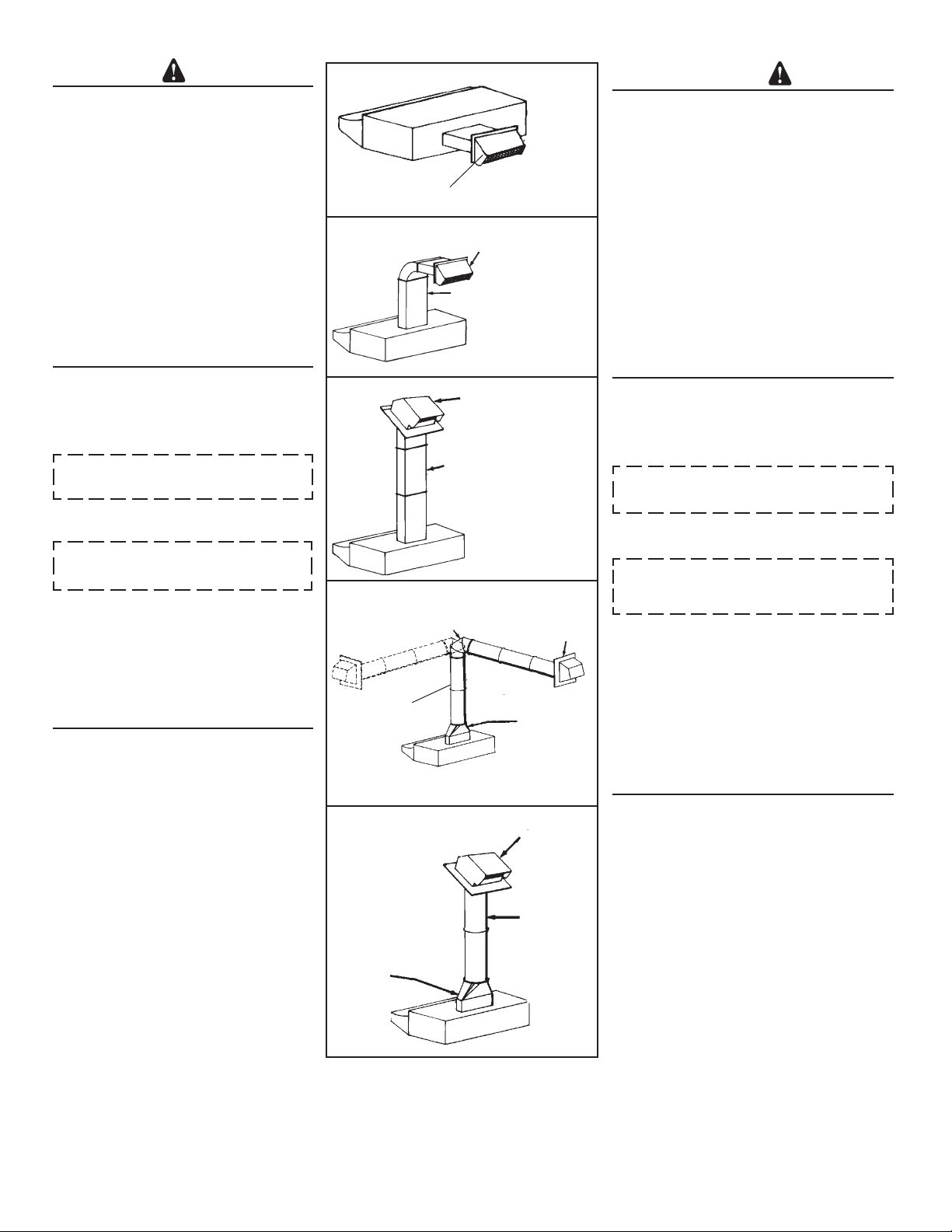
Begin planning ductwork by deciding where the duct will
run between the range hood and the outside. For best
performance, use the shortest possible duct run and a
minimum number of elbows. There are several choices
shown - FIGS. 1A - 1E.
In more complex ducting situations, a 3-1/4” rectangular
ducting range hood can be converted to a round duct
by means of a transition.
FIG. 1A. Ducting directly through the wall (for range
hoods mounted on an exterior wall). Shown are two
ways to duct through an outside wall. If a wall cap is used
directly off the back of the hood, special care must be
taken to make sure that the damper in the damper/duct
connector on the hood and damper in the wall cap do
not interfere with each other when the hood is operating. This could result in either inadequate air delivery
or back drafts. If this condition does exist, remove the
hood damper flap. Sometimes when using a wall cap
it is easier to duct vertically and then use an elbow as
shown in FIG. 1B.
FIG. 1C. Ducting straight up through the roof using
3-1/4” x 10” rectangular duct. (For single story
installations.)
FIG. 1D. Ducting between the ceiling joists (for multistory installations) or through the soffit space above the
cabinets (where the soffit connects to an outside wall).
FIG. 1E. Straight up through the roof using 6” round duct
(for single-story installations).
FIG. 1C
FIG. 1D
ADJUSTABLE ELBOW 419
CODO AJUSTABLE 419
6” ROUND DUCT 406
DUCTO REDONDO DE
6” 406
FIG. 1E
3-1/4” x 10” TO 6”
ROUND DUCT
TRANSITION 411
TRANSICIÓN DE
3-1/4” x 10” A
UN DUCTO
REDONDO
DE 6” 411
ROOF CAP 634 OR 644
CASQUETE DE
TECHO 634 O 644
3-1/4” x 10” DUCT 401
DUCTO DE
3-1/4” x 10” 401
WALL CAP 641
CASQUETE DE
PARED 641
3-1/4” x 10” TO 6”
ROUND DUCT
TRANSITION 411
TRANSICIÓN DE
3-1/4” x 10” A
UN DUCTO
REDONDO
DE 6” 411
ROOF CAP 634 OR 644
CASQUETE DE TECHO 634 O 644
6” ROUND DUCT
406
DUCTO REDONDO
DE 6” 406
HERRAMIENTAS Y MATERIALES QUE SE REQUIEREN
HERRAMIENTAS
q Taladro, eléctrico o trinquete
q Broca tipo pala de 1-1/4”
q Destornillador de ranura o tipo phillips
q Pinzas o tenazas
q Medidor de cinta o regla y lápiz
Para instalaciones con ducto SOLAMENTE:
q Sierra tipo sable o sierra para tabiques
q Alicate para cortar
MATERIALES
q Suministros y alambre eléctrico del tipo que cumplen
con los códigos locales
q Casquete de techo o pared
q Cemento o pega de techa o material de calafatear
o rellenar
q Ductos y cinta aislante para ductos
Para instalación en gabinetes de cocina con la parte inferior
ahuecada solamente:
q Dos tiras de madera 1” x 2” x 12” (largo aproximado)
(cómpreselas localmente)
q Cuatro tornillos para madera de cabeza plana de 1-1/4”
de largo (cómpreselas localmente) para sujetar las tiras
de madera a la parte inferior de gabinete
PLANIFICANDO LA INSTALACION DE LOS DUCTOS
Comience el trabajo de los ductos decidiendo el camino que
el ducto tomará entre el extractor y la parte exterior de la
casa. Para mejor rendimiento, use el camino de ducto más
corto posible y un mínimo de codos. Se muestran varias
elecciones - FIGS. 1A - 1E.
En situaciones de paso del ducto más complejas, el extractor
con conexión para ducto rectangular puede convertirse en
conexión redonda usando una transición.
FIG. 1A. Pasando el ducto directamente a través de la pared
(para los extractores que están instalados en una pared
exterior). Se muestran dos maneras de pasar el ducto a
través de la pared exterior. Si se usa un casquete de pared
directamente en la parte de atrás del extractor hay que
asegurarse que el regulador en el conector entre ducto y
regulador en el extractor, y el regulador en el casquete de
pared no interfieran el uno con el otro cuando el extractor esté
operando. Esto podría resultar en paso de aire inadecuado
o corrientes invertidas. Si esta condición existe, quite la hoja
instalada en el regulador del extractor. A veces cuando
se usa un casquete de pared es más fácil pasar el ducto
verticalmente y usar un codo como se muestra en FIG. 1B.
FIG. 1C. Haciendo un ducto directamente al techo usando
un ducto rectangular de 3-1/4” x 10” (para instalaciones en
un piso solamente).
FIG. 1D. Instalando un ducto entre las vigas del techo (para
instalaciones en más de un piso) o a través del espacio
de sofito arriba de los gabinetes (cuando el sofito está
conectado a una pared exterior).
FIG. 1E. Directamente hacia el techo usando ducto redondo
de 6” (para instalaciones de un piso).
2
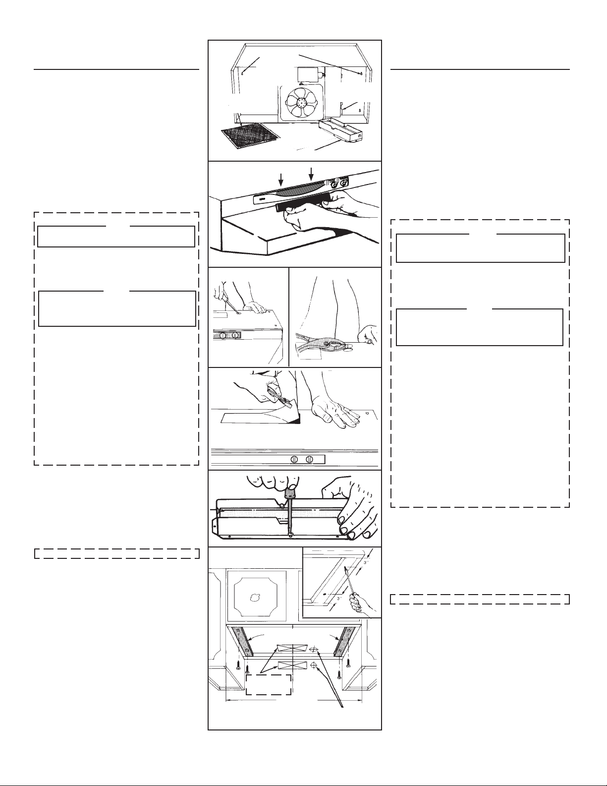
PREPARING THE RANGE
HOOD
1. Unpack hood and check contents. You should
receive:
1 - Aluminum Filter
1 - 3-1/4” x 10” Damper/Duct Connector (mounted
inside of hood for shipping only) (Save screws for
mounting.)
1 - 7” Round Duct Plate (mounted on top of hood)
(not shown) (Save screws for mounting.)
2. Remove 7” round duct plate from top of hood. Set
duct plate aside - with mounting screws.
3. Remove wiring box cover. Under cover find:
1 - Plastic Bag containing loose mounting hardware
4. For non-ducted installation, remove louver cover
from front of hood. (FIG. 3)
5. Remove either top or rear electrical knockout depending upon whether wiring will enter hood from wall or
cabinet. (FIG. 4)
DUCTED INSTALLATION ONLY
Louver cover must be installed as shown in
Figure 3 to function in ducted mode.
6. Remove appropriate duct knockout on hood by
inserting screwdriver into edge of knockout and
breaking tabs holding knockout to hood. You may
have to tap screwdriver with hammer to break
tabs. Peel knockout back with pliers. (FIG. 5)
TAKE CARE WHEN REMOVING THE 3¼” X
10” VERTICAL DUCT KNOCKOUT. DO NOT
DAMAGE THE 7” ROUND DUCT KNOCKOUT.
7. Fit damper/duct connector over opening and
secure in place with black sheet metal screws.
(FIG. 6)
Hinge pins and damper/duct connector should
be toward top of hood for ducting through wall or
toward back of hood for ducting through cabinet
above hood. Seal joint between damper/duct
connector and hood with duct tape.
8. 7” round ducted discharge only: Re-install 7”
round duct plate removed in Step #2 under “PREPARING THE RANGE HOOD” section. For best
performance, line up the 7” round duct plate
with the 7” round opening on hood. Mount
duct plate to hood with 2 screws from duct plate
and 2 screws from 3¼” x 10” damper. Install a 7”
round damper (purchase separately). Damper
flap must open freely in direction of air flow (away
from range hood).
OMIT STEP 9 if range hood will be installed under
cabinets with flush bottom.
9. (For installation on recessed bottom cabinets only)
Attach a wood filler strip at each side of recessed
area under cabinet. (Use two 1” x 2” strips cut to
length.) If recess is more than 1” use thicker strips.
Attach strips with 1-1/4” screws about 3” from each
end. See FIG. 7.
10. Measure and mark the following (FIGS. 7 & 8):
a) Electrical line opening
b) Duct opening
11. Drill four pilot holes in corners of marked duct opening as shown and cut opening with saber saw or
keyhole saw.
12. Use 1-1/4” drill bit to drill opening for electrical connection in wall or cabinet.
13. Hold hood up against cabinet bottom and trace
keyhole slots onto cabinet bottom of filler strips.
14. Screw the four supplied 7/8” wood screws for
mounting the hood into the exact center of the narrow end of the keyhole slots marked underneath
the cabinet. Allow 3/8” of the screws to project, so
the hood can be fitted into place.
NOTE
NOTE
FIG. 2
ALUMINUM FILTER
FILTRO DE ALUMINIO
FIG. 3
FIG. 4
FIG. 5
FIG. 6
FIG. 7
KEYHOLE SLOTS
RANURAS EN FORMA
DE HUECO DE CER-
RADURA
DAMPER/DUCT CONNECTOR
CONECTOR AL REGULADOR/DUCTO
CUT STRIPS TO FIT
CORTE LAS TIRAS PARA
QUE QUEPAN
DUCT OPENINGS
ABERTURA PARA
EL DUCTO
CENTER LINE
LINEA CENTRICA
WIDTH OF
RANGE HOOD
ANCHO DEL
EXTRACTOR
WIRING BOX COVER
TAPA DE LA CAJA DE
CABLEADO
ELECTRICAL WIRING OPENING
ABERTURA PARA EL CABLEADO ELECTRICO
PREPARANDO EL
EXTRACTOR
1. Desempaque el extractor y revise el contenido de la caja.
Usted debe de encontrar:
1 -Filtro de aluminio
1 -Conector de ducto/regulador de 3-1/4” x 10”
(montado dentro del extractor para embarque
solamente) (Guarde los tornillos para el montaje.)
1-Placa del conducto redondo de 7” (montado en del extrac-
tor) (no se muestra) (Guarde los tornillos para el montaje.)
2. Quite la placa del conducto redondo de 7” de la parte superior de la campana. Colóquela aparte, con los tornillos
de montaje.
3. Quite la cubierta de la caja de cableado. Bajo la tapa
encontrará:
1 -Una bolsa de plástico que contiene herrajes
sueltos para instalación
4. Para instalaciones sin ducto, quite la tapa de la rejillas de
la parte frontal del extractor. (FIG. 3)
5. Quite la tapa de quitar golpeando eléctrica de arriba o atrás
dependiendo en donde entra el cableado al extractor de la
pared o del gabinete. (FIG. 4)
INSTALACION CON DUCTO SOLAMENTE
La cubierta de las rejillas se debe instalar como se
muestra en la figura 3 para que funcione con el
6. Quite la placa de quitar golpeando en el extractor
insertando un destornillador en el filo y rompiendo las
conexiones que lo sostienen al extractor. Es posible que
tenga que golpear el destornillador con un martillo para
romper estas uniones. Pele la tapa de quitar golpeando
hacia atrás con una tenaza. (FIG. 5)
TENGA CUIDADO AL QUITAR EL AGUJERO CIEGO
DEL CONDUCTO VERTICAL DE 8.25 X 25.4 CM
(3¼” X 10”). NO DAÑE EL AGUJERO CIEGO DEL
CONDUCTO REDONDO DE 17.78 CM (7”).
7. Junte el conector del regulador/ducto sobre la abertura
y sujételo en su sitio con tornillos negros de metal para
lámina. (FIG. 6)
Los pasadores de bisagra y el conector del regulador/
ducto deben de estar hacia la parte de arriba del extractor para pasar el ducto a través de la pared o hacia la
parte de atrás del extractor para pasar el ducto a través
de gabinete encima del extractor. Selle la unión entre
el conector regulador/ducto con cinta de ducto.
8. Sólo para descargas con conducto redondo de 7”:
Vuelva la instalar la placa del conducto redondo de 7”
que quitó en el paso 2 de la sección “PREPARANDO
EL EXTRACTOR.” Para obtener un mejor rendimento,
alinee la placa del conducto redondo de 17.8 cm (7”)
con la abertura redonda de 17.8 cm (7”) de la campana.
Monte la placa del conducto al la campana con does
tornillos desde la placa del conducto y con dos tornillos
desde el tiro de 8.3 x 25.4 cm (3¼” x 10”). Instale un
regulador de tiro redondo de 7” (se compra por separado). La aleta del regulador se debe abrir libermente
en dirección del flujo de aire (en sentido contrario a la
campana la estufa).
OMITA PASO 9 si el extractor estará instalado debajo de un
gabinete con la parte inferior plana.
9. (Para instalación en gabinetes ahuecados solamente)
Sujete una tira de madera a cada lado de la parte inferior
ahuecada debajo del gabinete. (Use dos tiras de madera
de 1” x 2” cortadas al largo necesario.) Si el ahuecamiento
es más de 1” use tiras más gruesas. Sujete las tiras con
tornillos de 1-1/4” a una distancia de más o menos 3” del
extremo. Véase FIG. 7.
10. Mida y marque lo siguiente (FIG. 7 & 8):
a) Abertura para la línea eléctrica
b) Abertura para el ducto
11. Perfore cuatro huecos pilotos en las esquinas ya marca-
das de la abertura para el ducto como se muestra y luego
corte un abertura con un serrucho sable o un serrucho
para cerradura.
12. Usese una broca de 1-1/4” para perforar una abertura
para la conexión eléctrica en la pared o gabinete.
13. Sostenga al extractor debajo de la parte inferior del gabi-
nete y trace las ranuras en forma de hueco de cerradura
en la parte inferior del gabinete donde se instalarán las
tiras de madera.
14. Atornille cuatro de los tornillos de madera de 7/8” para
montar el extractor en el centro exacto de la parte
estrecha de la ranuras en forma de cerradura que se
marcaron debajo del gabinete. Permita que 3/8” de los
tornillos queden afuera, para que luego pueda instalarse
al extractor en su sitio.
NOTA
conducto.
NOTA
3
 Loading...