


QUICKSTART GUIDE
ENGLISH ( 3 – 8 )
MANUAL DE INICIO RÁPIDO
ESPAÑOL ( 9 – 14 )
GUIDE D’UTILISATION RAPIDE
FRANÇAIS ( 15 – 20 )
MANUALE RAPIDO DI UTILIZZAZIONE
ITALIANO ( 21 – 26 )
KURZANLEITUNG
DEUTSCH ( 27 – 32 )

INTRODUCTION
Welcome to the X6 professional 2-channel mixer. Here are some of the features that you will come to love about this device:
24-bit digital mixing with noise-free controls
12 effects (6 for Channel 1/Channel 2; 6 for Mic/Aux), routable to Channel 1, Channel 2, Mic/Aux, or Master
Comprehensive, easy-to-use effects interface includes beat sync tap button, wet/dry fader, and rotary parameter control
Steep 3-band EQ on each input channel with EQ Kill switches
Variety of inputs (2 phono with phono defeat switch, 2 line, and 1 mic/stereo aux)
Smooth crossfader with continuous rotary slope control and reverse switch
Look-ahead peak limiting on headphone and master outputs
We hope that the X6 serves you well for many years to come.
Sincerely,
The People of Numark
BOX CONTENTS
X6
AC Power Adapter
Quickstart Guide
Safety & Warranty Information Booklet
REGISTRATION
Please go to http://www.numark.com to register your X6. with any last-minute product developments and provide problems.
Registering your product ensures that we can keep you up-to-date you with world-class technical support, should you run into any
GROUND RULES
1.Make sure all items listed in the BOX CONTENTS section are included in the box.
2.READ SAFETY & WARRANTY INFORMATION BOOKLET BEFORE USING THE PRODUCT.
3.Study the connection diagram in this guide.
4.Place mixer in an appropriate position for operation.
5.Make sure all devices are turned off and all faders and gain knobs are set to “zero”
6.Connect all stereo input sources as indicated in the diagram.
7.Connect the stereo outputs to power amplifier(s), tape decks, and/or other audio sources.
8.Plug all devices into AC power.
9.Switch everything on in the following order.
•audio input sources (i.e. turntables, CD players, etc.)
•mixer
•last, any amplifiers or output devices
10.When turning off, always reverse this operation by,
•turning off amplifiers
•mixer
•last, any input devices
3
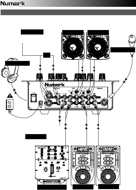
CONNECTION DIAGRAM
CD BURNER |
TURNTABLE TURNTABLE |
MICROPHONE |
OR |
HEADPHONES |
HOUSE AMP
REMOTE MIXER |
CD PLAYER CD PLAYER |
4
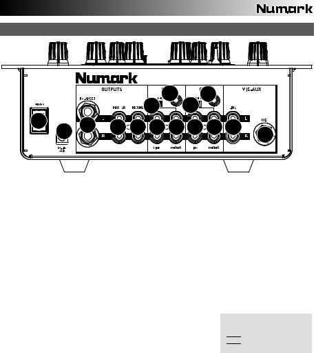
REAR PANEL FEATURES
|
|
|
|
|
5 |
6 |
5 |
6 |
|
|
|
|
|
|
|
|
|
||
11 |
10 |
9 |
8 |
7 |
4 |
3 |
4 |
3 |
2 |
|
|||||||||
|
|
|
|
|
|
|
|
1 |
1.MIC INPUT – Connect a ¼” microphone to this input. Microphone controls are located on the top panel.
2.MIC-AUX LINE INPUT (RCA) – Connect a line-level device, such as a CD player, sampler, or audio interface, to this input. The audio levels for this input are controlled by the microphone controls on the top panel.
3.LINE | PHONO INPUTS (RCA) – Connect your audio sources to these inputs. These inputs can accept both line and phono-level signals.
4.LINE INPUTS (RCA) – Connect line-level devices, such as CD players, samplers or audio interfaces, to these inputs.
5.LINE | PHONO SWITCH – Flip this switch to the appropriate position, depending on the device connected to the LINE | PHONO INPUTS. If you are using phono-level turntables, set this switch to “PHONO” to provide the additional amplification needed for phono-level signals. If using a line-level device, such as a CD player or sampler, set this switch to “LINE.”
6.GROUNDING TERMINAL – If using phono-level turntables with a grounding wire, be sure to connect the grounding wire to these terminals. If you experience a low “hum” or “buzz”, this could mean that your turntables are not grounded.
Note: Some turntables have the grounding wire built into the RCA connection and, therefore, nothing needs to be connected to the grounding terminal.
7.RECORD OUTPUT (RCA) – Use standard RCA cables to connect this output to a recording device, such as a CD recorder or tape deck. The level of this output is based upon pre-master levels.
8.MASTER OUTPUT (RCA) – Use standard RCA cables to connect this output to a speaker or amplifier system. The level of this output is controlled by the MASTER knob on the top panel.
9.MASTER OUTPUT (BALANCED) – Use balanced ¼” (TRS) cables to connect
this Master output to a speaker or amplifier system. The level of this output is controlled by the Master knob on the top panel.
Tip: When possible, we recommend using these balanced outputs for your Master audio output. Balanced outputs are better suited for long cable runs and are less susceptible to noise and interference.
How do I know if my ¼” cables are balanced?


 BALANCED

 UNBALANCED
10.AC IN – Use the included power adapter to connect the mixer to a power outlet. While the power is switched off, plug the power supply into the mixer first, then plug the power supply into a power outlet.
Note: The mixer is designed to work with the included AC power supply only. Using an incompatible power supply could result in damage to the unit.
11.POWER SWITCH – Turns the mixer on and off. Turn on the mixer after all input devices have been connected and before you turn on amplifiers. Turn off amplifiers before you turn off the mixer.
5
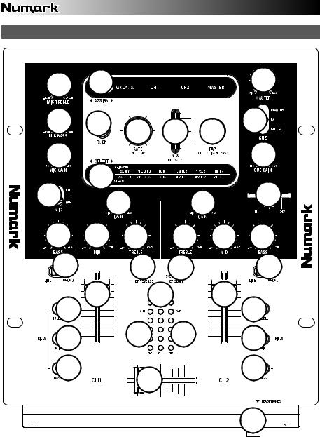
TOP PANEL FEATURES
4 |
23 |
|
|
|
19 |
3 |
22 |
25 |
26 |
27 |
15 |
|
|
|
|||
2 |
|
|
|
|
11 |
1 |
24 |
|
|
|
13 |
|
5 |
|
5 |
||
|
|
|
|
||
6 |
7 |
8 |
8 |
7 |
6 |
9 |
|
17 |
18 |
|
9 |
21 |
10 |
|
14 |
10 |
21 |
|
|
|
|
||
21 |
|
20 |
20 |
|
21 |
21 |
|
16 |
|
21 |
|
|
|
|
|
||
|
|
|
|
|
12 |
6

1.MIC SWITCH – Turns the MIC INPUT and MIC-AUX LINE INPUT on or off.
2.MIC GAIN – Adjusts the audio level of the MIC INPUT and MIC-AUX LINE INPUT.
3.MIC BASS – Adjusts the low (bass) frequencies of the microphone channel.
4.MIC TREBLE – Adjusts the high (treble) frequencies of the microphone channel.
Tip: If you experience feedback when using a microphone at loud levels, try turning down the high frequencies.
5.CHANNEL GAIN – Adjusts the channel’s pre-fader and pre-EQ gain level.
6.CHANNEL BASS – Adjusts the low (bass) frequencies of the corresponding channel.
7.CHANNEL MID – Adjusts the mid-range frequencies of the corresponding channel.
8.CHANNEL TREBLE – Adjusts the high (treble) frequencies of the corresponding channel.
9.INPUT SELECTOR – Selects the input source to be routed to the corresponding channel. Input jacks are located on the rear panel.
10.CHANNEL FADER – Adjusts the audio level on the corresponding channel
11.CUE GAIN – Adjusts the volume level of the headphone output.
12.HEADPHONES – Connect your ¼” headphones to this output for cueing and mix monitoring. Headphone output controls are located on the top panel.
13.CUE SLIDER – When the CUE MODE SELECTOR is set to “CH1 – CH2,” this blends the audio from Channel 1 and 2 in the headphones. Sliding this to the left plays Channel 1. Sliding to the right plays Channel 2.
14.CUE METER – Monitors the audio level of the Cue Channel, depending on the position of the CUE MODE SELECTOR.
15.CUE MODE SELECTOR – Selects the audio that is sent to the headphones. Selecting MASTER routes the Program mix to the headphones. Selecting FX routes the effects block output to the headphones. (This allows you to cue the effects before applying it.) Selecting CH1-2 allows cueing of Channels 1 and 2 using the CUE SLIDER.
16.CROSSFADER – Blends audio between the channels assigned to the left and right side of the crossfader.
Note: The crossfader is user-replaceable if it should ever wear out. Simply remove the facepanel, then remove the screws holding it in position. Replace the fader with a quality authorized replacement from your local Numark retailer only.
17.CROSSFADER (CF) REVERSE – Reverses the assignment of Channels 1 and 2 on the crossfader.
18.CROSSFADER (CF) SLOPE – Adjusts the slope of the crossfader curve. Turn knob to the left for a smooth fade (mixing) or to the right for a sharp cut (scratching).
19.MASTER – Adjusts the output volume of the Program mix.
20.STEREO LEVEL INDICATOR – Monitors the audio level of the Program mix.
21.EQ KILL SWITCHES – Eliminates the bass, mid, or high frequencies of the corresponding channel.
22.EFFECTS (FX) ON – Turns effects processing on and off. Note that you will also have to raise the Intensity Mix control to be able to hear the effects once they have been turned on.
23. |
ASSIGN |
– This switch selects the audio source on which the effects will be applied: the MIC INPUT and MIC-AUX |
|
LINE INPUT (MIC-AUX), Channel 1 (CH1), Channel 2 (CH2), or the Program mix (MASTER). The selected group will |
|
|
illuminate as the switch is toggled. |
|
24. |
SELECT |
– This switch selects the effects group. The selected group will illuminate as the switch is toggled. When |
|
the ASSIGN switch is set to MIC/AUX, you can select from the effects on the bottom row. When the ASSIGN switch is |
|
|
set to CH1, CH2, or MASTER, you can select from the effects on the top row. |
|
25.RATE / FREQUENCY – Adjusts the rate / frequency of the selected effect.
26.MIX / INTENSITY – Controls the amount of effected (wet) vs. non-effected (dry) sound in the mix. With the fader down, no effected sound will be audible. With the fader up, only the effected sound will be heard.
27.TAP – In order to align tempo-synced effects with the beat, press the TAP button on the beat 3-4 times. The beat sync often works best when tapping half the tempo. For example, try tapping just on the snare drums (typically the “2” and “4” count).
When beat sync has been enabled, effects denoted with an asterisk (*) will have rates / frequencies related to the tempo (see “Effects Descriptions” section). You can use the RATE / FREQUENCY knob to adjust the beat-synced rate as a multiple of the tempo (1x, 2x, 4x, etc.)
To disable beat sync and have continuous control over the rate / frequency of an effect, press and hold trhe TAP button until it remains lit. Now the RATE / FREQUENCY knob allows you to precisely tune the rate / frequency of an effect.
To re-enable beat sync, tap out the beat again.
7

EFFECTS DESCRIPTIONS
The X6 features a comprehensive, easy-to-use multi-effects processor. We encourage you to spend some time becoming familiar with the operation and sound of each effect before you begin using them out at a performance. Although effects can add a level of interest and surprise to musical material, it is often easy to overdo it. Learn how to judiciously apply effects to your music and remember that sometimes your crowd just wants to hear the song.
CHANNEL EFFECTS – You can apply these effects to CH1, CH2, or MASTER by selecting the appropriate option with the ASSIGN switch.
2XCOPY * – A copy of the signal is delayed by a defined time. DJs will often keep 2 copies of a record for juggling tricks like this. Try using this effect with beat sync enabled and move the INTENSITY / MIX fader up and down to the tempo. Now use the RATE/FREQUENCY knob to try different multiples of the tempo.
TAPE ECHO * – A much sought-after echo effect, developed in the 1960s. In beat-sync mode, RATE/FREQUENCY controls the delay time as a multiple of the tempo (1x, 2x, 4X, etc). If beat sync has been disabled, RATE/FREQUENCY will control delay time continuously. The INTENSITY/MIX fader controls the input into the echo. This makes it very useful for selecting a phrase, vocal word or beat to echo. Simply turn up the INTENSITY/MIX fader momentarily during the snippet of music you wish to emphasize and bring it down. You’ll notice how the audio which was playing during that time will echo away. Now try turning up the INTENSITY/MIX fader for a whole measure, then cut the music out with the channel VOLUME fader. Let the music echo for a bit, then bring down the INTENSITY/MIX fader and cut the music back in.
ECHO – Regular echo effect. The configuration of this echo is a little different. This time, the INTENSITY/MIX fader controls the output of echo. When the fader is up, it will echo. Push the fader further, and it will feedback heavily, just like the tape echo. When the fader is at the bottom, the echo effect is cut out completely. This effect is very useful for juggling beats and emphasizing musical phrases.
FLANGER * – Sweeping flanger effect. In beat sync mode, the RATE/FREQUENCY controls the sweep rate as a multiple of the tempo. When beat synch is disabled, the RATE/FREQUENCY will continuously control the sweep rate. The INTENSITY/MIX controls the intensity of the flange effect.
PHASER * – Sweeping phase shifter effect. It is similar to the flanger effect, except that a flanger has a more pronounced harmonic sound, reminiscent of a jet engine passing overhead. A phase shifter is enharmonic, and has a “swooshing” sound. In beat sync mode, the RATE/FREQUENCY controls the sweep rate as a multiple of the tempo. When beat sync is disabled, the RATE/FREQUENCY will continuously control the sweep rate. The INTENSITY/MIX controls the intensity of the phase shifter effect.
LP FILTER – Low-pass filter effect. INTENSITY/MIX controls the amount of filtered signal which will be heard. RATE/FREQUENCY controls the filter’s cut-off frequency. When RATE/FREQUENCY is at its maximum value, there will be no filtering; as you begin to turn down the knob, the effect will begin to filter out the high (treble) frequencies of the audio.
MIC-AUX EFFECTS – You can apply these effects only to the MIC INPUT and MIC-AUX LINE INPUT by selecting MIC-AUX with the ASSIGN switch.
VOCODER – A square wave vocoder, reminiscent of the robot voice sounds from the early days of electronic music. RATE/FREQUENCY controls the pitch of the voice.
TAPE ECHO * – See description under CHANNEL EFFECTS.
ECHO – See description under CHANNEL EFFECTS.
REVERB 1 – Simulates hall reverberation. RATE/FREQUENCY controls the decay (size of room). INTENSITY/MIX controls the wet/dry mix.
REVERB 2 – Samples the audio and plays it in reverse while adding reverb. This is a very cool effect if you stab into the effect then immediately cut the sound using the channel VOLUME fader.
HP FILTER – High-pass filter effect. INTENSITY/MIX controls the amount of filtered signal which will be heard. RATE/FREQUENCY controls the filter’s cut-off frequency. When RATE/FREQUENCY is at its minimum value, there will be no filtering; as you begin to turn up the knob, the effect will begin to filter out the low (bass) frequencies of the audio.
LMT+DISTORT – Band-limited distortion effect. This effect is mainly intended to be used with a microphone. RATE/FREQUENCY controls the distortion amount, while INTENSITY/MIX controls the amount of distortion which will be mixed in.
(*) When beat sync has been enabled by tapping the TAP button to the beat, effects denoted with an asterisk (*) will have rates or times which are related to the tempo. Use the RATE/FREQUENCY knob to adjust the multiple of the tempo (1x, 2x, 4x, etc). To disable beat sync and have continuous control over rate/frequency, press and hold the TAP button until it remains lit continuously.
8

INTRODUCCIÓN
Bienvenido al mezclador profesional de 2 canales X6. He aquí algunas de las características de este dispositivo que seguramente le encantarán:
Mezcla digital de 24 bits con controles libres de ruido
12 efectos (6 para canal 1/canal 2 y 6 para micrófono/auxiliar), aplicables a canal 1, canal 2, micrófono/auxiliar o mezcla maestra
Interfaz de efectos completa y fácil de usar que incluye botón de golpes de sincronismo de beats, fader wet/dry (de señal con efectos/original) y control rotativo de parámetros
Excelente ecualizador de 3 bandas en cada canal de entrada, con interruptores de supresión de ecualización
Variedad de entradas (2 fonográficas con interruptor de supresión “phono defeat", 2 de línea y 1 de micrófono / auxiliar estéreo
Suave crossfader con control rotativo continuo de pendiente y conmutador de inversión
Limitación adelantada de picos en las salidas para auriculares y maestra
Esperamos que el X6 le brinde un buen servicio por muchos años.
Atentamente,
La Gente de Numark
CONTENIDO DE LA CAJA
X6
Adaptador de CA
Guía de inicio rápido
Folleto de información sobre la seguridad y la garantía
REGISTRO
Visite http://www.numark.com y registre su X6. El registro de su producto asegura que podamos mantenerle actualizado con los desarrollos de productos de último momento y brindarle apoyo técnico de categoría mundial en caso de que tenga algún problema.
REGLAS BÁSICAS
1.Asegúrese de que todos los artículos indicados en “Contenido de la caja" estén incluidos en la caja.
2.LEA EL FOLLETO DE INFORMACIÓN SOBRE LA SEGURIDAD Y LA GARANTÍA ANTES DE UTILIZAR EL PRODUCTO.
3.Estudie el diagrama de conexión incluido en esta guía.
4.Coloque el mezclador en una posición adecuada para su funcionamiento.
5.Asegúrese que todos los dispositivos estén apagados y que todos los faders y perillas de ganancia estén en posición «cero».
6.Conecte todas las fuentes de entrada estéreo como se indica en el diagrama.
7.Conecte las salidas estéreo a los amplificadores de potencia, bandejas de cinta magnética y/o otras fuentes de audio.
8.Enchufe todos los dispositivos al suministro de corriente alterna.
9.Encienda todo en el siguiente orden:
•fuentes de entrada de audio (por ejemplo, giradiscos, reproductores de CD, etc.)
•el mezclador
•por último, cualquier amplificador o dispositivo de salida
10.Al apagar, realice siempre esta operación en sentido inverso:
•apague los amplificadores
•el mezclador
•por último, cualquier dispositivo de entrada
9

ECTION DIAGRAM
DIAGRAMA DE CONEXIÓN
GRABADORA DE CD |
GIRADISCOS |
GIRADISCOS |
MICRÓFONO |
O |
AURICULARES |
AMPLIFICADOR
DE AUDITORIO
MEZCLADOR |
REPRODUCTOR |
REPRODUCTOR |
REMOTO |
DE CD |
DE CD |
10
CARACTERÍSTICAS DEL PANEL TRASERO
|
|
|
|
|
5 |
6 |
5 |
6 |
|
|
|
|
|
|
|
|
|
||
11 |
10 |
9 |
8 |
7 |
4 |
3 |
4 |
3 |
2 |
|
|||||||||
|
|
|
|
|
|
|
|
1 |
1.ENTRADA DE MICRÓFONO – Conecte un micrófono de 1/4” a esta entrada. Los controles de micrófono se encuentran en el panel superior.
2.ENTRADA MIC-AUX (De micrófono-línea auxiliar) (RCA) – Conecte a esta entrada un dispositivo de nivel de línea, como un reproductor de CD, muestreador o interfaz de audio. Los niveles de audio de esta entrada se controlan con los controles de micrófono del panel superior.
3.ENTRADAS DE LÍNEA | FONOGRÁFICA (RCA) – Conecte sus fuentes de audio a estas entradas. Estas entradas pueden aceptar señales de nivel de línea y fonográfico.
4.ENTRADAS DE LÍNEA – Estas entradas se usan para conectar dispositivos de nivel de línea, tales como reproductores de CD, muestreadores o interfaces de audio.
5.INTERRUPTOR DE ENTRADA DE LÍNEA | FONOGRÁFICA – Coloque este conmutador en la posición apropiada, en función del dispositivo conectado a las entradas LINE| PHONO. Si usa giradiscos de nivel fonográfico, coloque este conmutador en “PHONO” para proporcionar la amplificación adicional necesaria para las señales de este nivel. Si usa un dispositivo de nivel de línea, tal como un reproductor de CD o muestreador, coloque este conmutador en “LINE.”
6.TERMINAL DE TIERRA – Si usa giradiscos de nivel fonográfico con cable de conexión a tierra, asegúrese de conectar dicho cable a estos terminales. Si se experimenta un zumbido grave, puede significar que sus giradiscos no están conectados a tierra.
Nota: Algunos giradiscos tienen el cable de conexión a tierra incorporado a la conexión RCA y, por lo tanto, no es necesario conectar nada al terminal de tierra.
7.SALIDA PARA GRABACIÓN (RCA) – Use cables RCA estándar para conectar esta salida a un dispositivo de grabación, tal como un grabador de CD o bandeja de cinta. El nivel de esta salida se basa en los niveles pre-master.
8.SALIDA MAESTRA (RCA) – Use cables RCA estándar para conectar esta salida maestra a un sistema de altavoces o amplificador. El nivel de esta salida se controla con la perilla MASTER del panel superior.
9.SALIDA MAESTRA (BALANCEADA) – Use cables de ¼” balanceados
(TRS) para conectar esta salida maestra a un sistema de altavoces o amplificador. El nivel de esta salida se controla con la perilla MASTER del panel superior.
Consejo: Recomendamos usar estas salidas balanceadas, cuando sea posible, para la salida de audio maestra. Las salidas balanceadas funcionan mejor con tramos largos de cables y son menos susceptibles al ruido y la interferencia
¿Cómo sé si mis cables de ¼” son balanceados?


 BALANCEADO

 NO BALANCEADO
10.ENTRADA DE CA – Use el adaptador de alimentación incluido para conectar el mezclador a un tomacorriente alimentado. Mientras está desconectada la alimentación eléctrica, enchufe la fuente de alimentación al mezclador primero, y luego al tomacorriente.
Para tener en cuenta: El mezclador está diseñado para funcionar con la fuente de alimentación de CA de 9 V-1.5 únicamente . Si usa una fuente de alimentación incompatible se puede dañar la unidad.
11.INTERRUPTOR DE ENCENDIDO – Enciende y apaga el mezclador. Encienda el mezclador después de desconectar todos los dispositivos de entrada y antes de encender los amplificadores. Apague los amplificadores antes de apagar el mezclador.
11
 Loading...