


NSC SCANPSC110FE-QV, SCANPSC110FFMQB, SCANPSC110FJ-QV, SCANPSC110FLMQB, SCANPSC110FW-QV Datasheet
...October 1999
SCANPSC110F
SCAN Bridge Hierarchical and Multidrop Addressable
JTAG Port (IEEE1149.1 System Test Support)
General Description
The SCANPSC110F Bridge extends the IEEE Std. 1149.1 test bus into a multidrop test bus environment. The advantage of a hierarchical approach over a single serial scan chain is improved test throughput and the ability to remove a board from the system and retain test access to the remaining modules. Each SCANPSC110F Bridge supports up to 3 local scan rings which can be accessed individually or combined serially. Addressing is accomplished by loading the instruction register with a value matching that of the Slot inputs. Backplane and inter-board testing can easily be accomplished by parking the local TAP Controllers in one of the stable TAP Controller states via a Park instruction. The 32-bit TCK counter enables built in self test operations to be performed on one port while other scan chains are simultaneously tested.
nThe 6 slot inputs support up to 59 unique addresses, a Broadcast Address, and 4 Multi-cast Group Addresses
n3 IEEE 1149.1-compatible configurable local scan ports
nMode Register allows local TAPs to be bypassed, selected for insertion into the scan chain individually, or serially in groups of two or three
n32-bit TCK counter
n16-bit LFSR Signature Compactor
nLocal TAPs can be tri-stated via the OE input to allow an alternate test master to take control of the local TAPs
nThe IP version of this device supports features not described in this datasheet such as 8 slot inputs for enhanced address capability and additional instructions. For a completed description of the additional instructions supported, refer to the SCANPSC110 supplemental datasheet.
Features
n True IEEE1149.1 hierarchical and multidrop addressable capability
Connection Diagrams
28-Pin |
Pin Assignment for LCC |
CDIP and Flatpak |
|
DS100327-2
DS100327-1
TRI-STATE® is a registered trademark of National Semiconductor Corporation.
Bridge SCAN SCANPSC110F
© 1999 National Semiconductor Corporation |
DS100327 |
www.national.com |

SCANPSC110F
Connection Diagrams (Continued)
Order Number |
Description |
|
|
SCANPSC110FFMQB |
Military Flatpak |
SCANPSC110FDMQB |
Military DIP |
SCANPSC110FLMQB |
Military Leadless Chip Carrier |
|
|
Table of Contents
1.GLOSSARY OF TERMS: 2
2.DETAILED PIN DESCRIPTION TABLE: 3
3.OVERVIEW OF SCAN BRIDGE FUNCTIONS: 4
A.SCANPSC110F Bridge Architecture: 4
B.SCANPSC110F Bridge State Machines: 4
4.TESTER/SCANPSC110F BRIDGE INTERFACE: 8
5.REGISTER SET: 8
6.ADDRESSING SCHEME: 8
7.HIERARCHICAL TEST SUPPORT: 9
8.LEVEL 1 PROTOCOL: 9
A.Addressing Modes: 9
B.Direct Addressing: 10
C.Broadcast Addressing: 10
D.Multi-Cast Addressing: 10
9.LEVEL 2 PROTOCOL: 11
A.Level 2 Instruction Types: 11
|
Pin |
Description |
|
|
Names |
|
|
|
|
|
|
|
TCKB |
Backplane Test Clock Input |
|
|
TMSB |
Backplane Test Mode Select Input |
|
|
TDIB |
Backplane Test Data Input |
|
|
TDOB |
Backplane Test Data Output |
|
|
|
|
Asynchronous Test Reset Input (Active low) |
|
TRST |
|
|
|
S(0,5) |
Address Select Port |
|
|
OE |
|
Local Scan Port Output Enable (Active low) |
|
TCKL(1±3) |
Local Port Test Clock Output |
|
|
TMSL(1±3) |
Local Port Test Mode Select Output |
|
|
TDIL(1±3) |
Local Port Test Data Input |
|
|
TDOL(1±3) |
Local Port Test Data Output |
|
B.Level 2 Instruction Descriptions: 12
10.REGISTER DESCRIPTIONS: 14
11.SPECIAL FEATURES: 16
A.BIST Support: 16
B.RESET: 16
C.Port Synchronization: 16
12.ABSOLUTE MAXIMUM RATINGS: 18
13.RECOMMENDED OPERATING CONDITIONS: 18
14.DC ELECTRICAL CHARACTERISTICS: 18
15.AC ELECTRICAL CHARACTERISTICS: 20
16.AC WAVEFORMS: 22
17.APPENDIX: 24
A.State Diagram for Boundary-Scan TAP Controller: 24
18.APPLICATIONS EXAMPLE: 24
|
TABLE 1. Glossary of Terms |
|
|
LFSR |
Linear Feedback Shift Register. When enabled, will generate a 16-bit signature of sampled serial |
|
test data. |
LSP |
Local Scan Port. A four signal port that drives a ªlocalº (i.e. non-backplane) scan chain. (e.g., |
|
TCKL1, TMSL1, TDOL1, TDIL1) |
Local |
Local is used to describe IEEE Std. 1149.1 compliant scan rings and the SCANPSC110F Bridge |
|
Test Access Port that drives them. The term ªlocalº was adopted from the system test architecture |
|
that the 'PSC110F Bridge will most commonly be used in; namely, a system test backplane with a |
|
'PSC110F Bridge on each card driving up to 3 ªlocalº scan rings per card. (Each card can contain |
|
multiple 'PSC110Fs, with 3 local scan ports per 'PSC110F.) |
|
|
Park/Unpark |
Park, parked, unpark, and unparked, are used to describe the state of the LSP controller and the |
|
state of the local TAP controllers (the ªlocal TAP controllersº refers to the TAP controllers of the |
|
scan components that make up a local scan ring). Park is also used to describe the action of |
|
parking a LSP (transitioning into one of the Parked LSP controller states). It is important to |
|
understand that when a LSP controller is in one of the parked states, TMSL is held constant, |
|
thereby holding or ªparkingº the local TAP controllers in a given state. |
TAP |
Test Access Port as defined by IEEE Std. 1149.1 |
|
|
Selected/Unselected |
Selected and Unselected refers to the state of the 'PSC110F Bridge Selection Controller. A |
|
selected 'PSC110F has been properly addressed and is ready to receive Level 2 protocol. |
|
Unselected 'PSC110Fs monitor the system test backplane, but do not accept Level 2 protocol |
|
(except for the GOTOWAIT instruction). The data registers and LSPs of unselected 'PSC110Fs are |
|
not accessible from the system test master. |
|
|
www.national.com |
2 |

Table of Contents (Continued)
|
TABLE 1. Glossary of Terms (Continued) |
Active Scan Chain |
The Active Scan Chain refers to the scan chain configuration as seen by the test master at a given |
|
moment. When a 'PSC110F is selected with all of its LSPs parked, the active scan chain is the |
|
current scan bridge register only. When a LSP is unparked, the active scan chain becomes: TDIB |
|
→ the current 'PSC110F register → the local scan ring registers → a PAD bit → TDOB. Refer to |
|
Table 4 for Unparked configurations of the LSP network. |
|
|
Level 1 Protocol |
Level 1 is the protocol used to address a 'PSC110F. |
Level 2 Protocol |
Level 2 is the protocol that is used once a 'PSC110F is selected. Level 2 protocol is IEEE Std. |
|
1149.1 compliant when an individual 'PSC110F is selected. |
|
|
PAD |
A one bit register that is placed at the end of each local scan port scan-chain. The PAD bit |
|
eliminates the prop delay that would be added by the 'PSC110F LSPN logic between TDILn and |
|
TDOL(n+1) or TDOB by buffering and synchronizing the TDIL inputs to the falling edge of TCKB, |
|
thus allowing data to be scanned at higher frequencies without violating set-up and hold times. |
|
|
LSB |
Least Significant Bit, the right-most position in a register (bit 0) |
|
|
MSB |
Most Significant Bit, the left-most position in a register |
|
|
TABLE 2. Detailed Pin Description Table
|
|
|
|
|
Pin # |
|
|
Name |
I/O (Note 1) |
(SOIC |
Description |
||
|
|
|
|
|
& LCC) |
|
|
|
|
|
|
|
|
|
TMSB |
TTL Input w/Pull-Up |
10 |
BACKPLANE TEST MODE SELECT: Controls sequencing through the TAP |
||
|
|
|
|
Resistor |
|
Controller of the SCANPSC110F Bridge. Also controls sequencing of the TAPs |
|
|
|
|
|
|
which are on the three (3) local scan chains. |
|
|
|
|
|
|
|
|
TDIB |
TTL Input w/Pull-Up |
12 |
BACKPLANE TEST DATA INPUT: All backplane scan data is supplied to the |
||
|
|
|
|
Resistor |
|
'PSC110F through this input pin. |
|
|
|
|
|
|
|
|
TDOB |
TRI-STATEable, |
13 |
BACKPLANE TEST DATA OUTPUT: This output drives test data from the |
||
|
|
|
|
32 mA/64 mA Drive, |
|
'PSC110F and the local TAPs, back toward the scan master controller. |
|
|
|
|
Reduced-Swing, |
|
|
|
|
|
|
Output |
|
|
|
|
|
|
|
|
|
TCKB |
TTL Schmitt Trigger |
11 |
TEST CLOCK INPUT FROM THE BACKPLANE: This is the master clock |
|||
|
|
|
|
Input |
|
signal that controls all scan operations of the 'PSC110F and of the three (3) |
|
|
|
|
|
|
local scan ports. |
|
|
|
|
|
|
|
|
|
|
TTL Input w/Pull-Up |
9 |
TEST RESET: An asynchronous reset signal (active low) which initializes the |
|
|
TRST |
|
||||
|
|
|
|
Resistor |
|
'PSC110F logic. |
|
|
|
|
|
|
|
S(0±5) |
TTL Inputs |
2, 3, 4, |
SLOT IDENTIFICATION: The configuration of these six (6) pins is used to |
|||
|
|
|
|
|
5, 6, 7 |
identify (assign a unique address to) each 'PSC110F on the system backplane. |
|
|
|
|
|
|
|
|
TTL Input |
1 |
OUTPUT ENABLE for the Local Scan Ports, active low. When high, this |
|||
|
OE |
|
||||
|
|
|
|
|
|
active-low control signal TRI-STATEs all three local scan ports on the |
|
|
|
|
|
|
'PSC110F, to enable an alternate resource to access one or more of the three |
|
|
|
|
|
|
(3) local scan chains. |
|
|
|
|
|
|
|
|
TDOL(1±3) |
TRI-STATEable, |
15,19, |
TEST DATA OUTPUTS: Individual output for each of the three (3) local scan |
||
|
|
|
|
24 mA/24 mA |
24 |
ports. |
|
|
|
|
Drive Outputs |
|
|
|
|
|
|
|
|
|
TDIL(1±3) |
TTL Inputs w/Pull-Up |
18, 23, |
TEST DATA INPUTS: Individual scan data input for each of the three (3) local |
|||
|
|
|
|
Resistors |
27 |
scan ports. |
|
|
|
|
|
|
|
TMSL(1±3) |
TRI-STATEable, |
16, 20, |
TEST MODE SELECT OUTPUTS: Individual output for each of the three (3) |
|||
|
|
|
|
24 mA/24 mA |
25 |
local scan ports. TMSL does not provide a pull-up resistor (which is assumed |
|
|
|
|
Drive Outputs |
|
to be present on a connected TMS input, per the IEEE 1149.1 requirement) |
|
|
|
|
|
|
|
|
|
|
|
|
|
|
TCKL(1±3) |
TRI-STATEable, |
17, 22, |
LOCAL TEST CLOCK OUTPUTS: Individual output for each of the three (3) |
|||
|
|
|
|
24 mA/24 mA |
26 |
local scan ports. These are buffered versions of TCKB. |
|
|
|
|
Drive Output |
|
|
|
|
|
|
|
|
|
VCC |
Power Supply Voltage |
8, 28 |
Power supply pins, 5.0V ± 10%. |
|||
SCANPSC110F
3 |
www.national.com |
SCANPSC110F
Table of Contents (Continued)
TABLE 2. Detailed Pin Description Table (Continued)
|
|
Pin # |
|
Name |
I/O (Note 1) |
(SOIC |
Description |
|
|
& LCC) |
|
|
|
|
|
GND |
Ground potential |
14, 21 |
Power supply pins 0V. |
|
|
|
|
Note 1: All pins are active HIGH unless otherwise noted.
Overview of SCANPSC110F Bridge Functions
DS100327-3
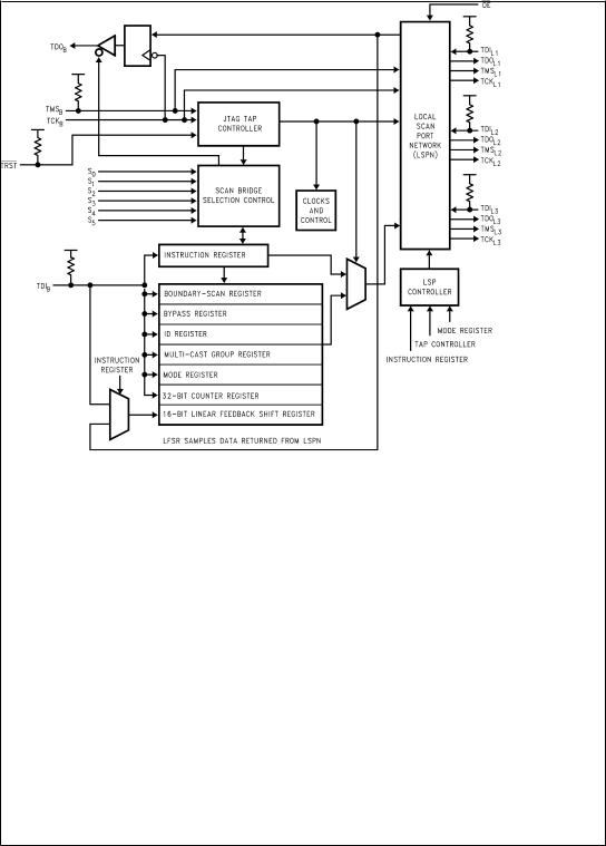
FIGURE 1. SCANPSC110F Bridge Architecture
SCANPSC110F BRIDGE ARCHITECTURE
Figure 1 shows the basic architecture of the 'PSC110F. The device's major functional blocks are illustrated here. The TAP Controller, a 16-state state machine, is the central control for the device. The instruction register and various test data registers can be scanned to exercise the various functions of the 'PSC110F (these registers behave as defined in IEEE Std. 1149.1).
The 'PSC110F selection controller provides the functionality that allows the 1149.1 protocol to be used in a multi-drop environment. It primarily compares the address input to the slot identification and enables the 'PSC110F for subsequent scan operations.
The Local Scan Port Network (LSPN) contains multiplexing logic used to select different port configurations. The LSPN control block contains the Local Scan Port Controllers (LSPC) for each Local Scan Port (LSP1, LSP2, and LSP3). This control block receives input from the 'PSC110F instruction register, mode register, and the TAP controller. Each local port contains all four (4) boundary scan signals needed to interface with the local TAPs.
SCANPSC110F BRIDGE STATE MACHINES
The 'PSC110F is IEEE 1149.1-compatible, in that it supports all required 1149.1 operations. In addition, it supports a higher level of protocol, (Level 1), that extends the IEEE 1149.1 Std. to a multi-drop environment.
www.national.com |
4 |

Overview of SCANPSC110F Bridge
Functions (Continued)
In multi-drop scan systems, a scan tester can select individual 'PSC110Fs for participation in upcoming scan operations. 'PSC110F ªselectionº is accomplished by simultaneously scanning a device address out to multiple
'PSC110Fs. Through an on-chip address matching process, only those 'PSC110Fs whose statically-assigned address matches the scanned-out address become selected to receive further instructions from the scan tester. 'PSC110F selection is done using a ªLevel-1º protocol, while follow-on instructions are sent to selected 'PSC110Fs by using a ªLevel-2º protocol.
DS100327-4
FIGURE 2. SCANPSC110F Bridge State Machines
The 'PSC110F contains three distinct but coupled state-machines (see Figure 2 ). The first of these is the TAP-control state-machine, which is used to drive the 'PSC110Fs scan ports in conformance with the 1149.1 Standard (see Figure 17 of appendix). The second is the 'PSC110F-selection state-machine (Figure 3). The third state-machine actually consists of three identical but independent state-machines (see Figure 4), one per 'PSC110F local scan port. Each of these scan port-selection state-machines allows individual local ports to be inserted into and removed from the 'PSC110Fs overall scan chain.
The 'PSC110F selection state-machine performs the address matching which gives the 'PSC110F its multi-drop capability. That logic supports single-'PSC110F access, multi-cast, and broadcast. The 'PSC110F-selection state-machine implements the chip's Level-1 protocol.
SCANPSC110F
5 |
www.national.com |
SCANPSC110F
Overview of SCANPSC110F Bridge Functions (Continued)
DS100327-5
KEY
+ = OR
& = AND
ADDR = 6-bit address in the Instruction Register
SLOT = Static address in the 'PSC110F Selection Controller
FIGURE 3. State Machine for SCANPSC110F Bridge Selection Controller
DS100327-12
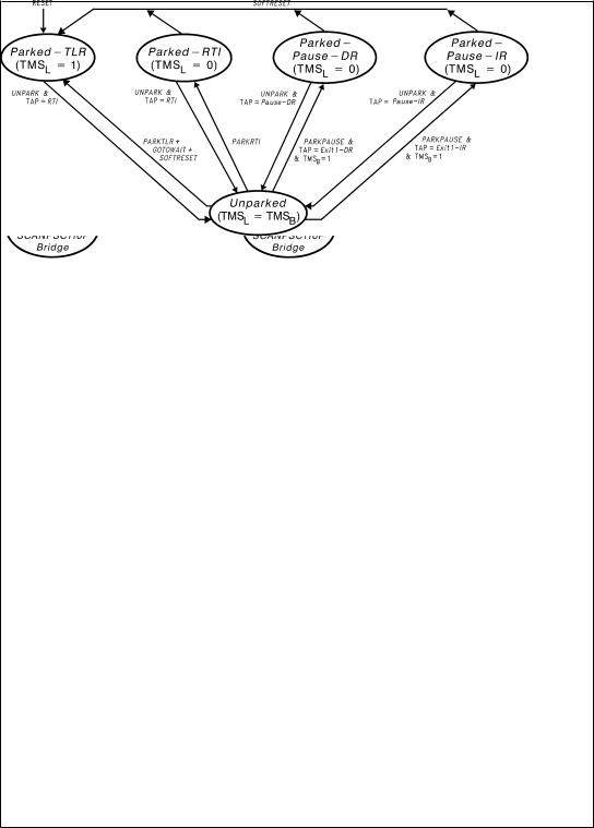
FIGURE 4. Local SCANPSC110F Bridge Port Configuration State Machine
The 'PSC110F's scan port-configuration state-machine is used to control the insertion of local scan ports into the overall scan chain, or the isolation of local ports from the chain. From the perspective of a system's (single) scan controller, each 'PSC110F presents only one scan chain to the master. The 'PSC110F architecture allows one or more of the 'PSC110F's local ports to be included in the active scan chain.
Each local port can be ªparkedº in one of four stable states
(Parked-TLR, Parked-RTI, Parked-Pause-DR or Parked-Pause-IR), either individually or simultaneously with
other local ports. Parking a chain removes that local chain from the active scan chain. Conversely, a parked chain can be ªunparkedº, causing the corresponding local port to be inserted into the active scan chain.
As shown in Figure 4, the 'PSC110F's three scan port-configuration state-machines allow each of the part's local ports to occupy a different state at any given time. For example, some ports may be parked, perhaps in different states, while other ports participate in scan operations. The state-diagram shows that some state transitions depend on the current state of the TAP-control state-machine. As an ex-
www.national.com |
6 |

Overview of SCANPSC110F Bridge
Functions (Continued)
ample, a local port which is presently in the Parked-RTI state does not become unparked (i.e., enter the Unparked state) until the 'PSC110F receives an UNPARK instruction and the 'PSC110F's TAP state-machine enters the Run-Test/Idle state.
Similarly, certain transitions of the scan port-configuration state-machine can force the 'PSC110F's TAP-control state-machine into specific states. For example, when a local port is in the Unparked state and the 'PSC110F receives a PARKRTI instruction, the Local Port controller enters the Parked-RTI state in which TMSLn will be held low until the port is later unparked. While TMSLn is held low, all devices on that local scan chain remain in their current TAP State (the RTI TAP controller state in this example).
The 'PSC110F's scan port-configuration state-machine implements part of the 'PSC110F's Level-2 protocol. In addition, the 'PSC110F provides a number of Level-2 instructions for functions other than local scan port confguration. These instructions provide access to and control of various registers within the 'PSC110F. This set instructions includes:
BYPASS |
CNTRSEL |
EXTEST |
LFSRON |
SAMPLE/PRELOAD |
LFSROFF |
IDCODE |
CNTRON |
MODESEL |
CNTROFF |
MCGRSEL |
GOTOWAIT |
LFSRSEL |
|
Figure 5 illustrates how the 'PSC110F's state-machines interact. The 'PSC110F-selection state-machine enables or disables operation of the chip's three port-selection state-machines. In 'PSC110Fs which are selected via Level-1 protocol (either as individual 'PSC110Fs or as members of broadcast or multi-cast groups), Level-2 protocol commands can be used to park or unpark local scan ports. Note that most transitions of the port-configuration state-machines are gated by particular states of the 'PSC110F's TAP-control state-machine, as shown in Figures 4, 5.
DS100327-6
FIGURE 5. Relationship Between SCANPSC110F Bridge State Machines
SCANPSC110F
7 |
www.national.com |

SCANPSC110F
Overview of SCANPSC110F Bridge
Functions (Continued)
Following a hardware reset, the TAP controller state-machine is in the Test-Logic-Reset (TLR) state; the 'PSC110F-selection state-machine is in the Wait-For-Address state; and each of the three port-selection state-machines is in the Parked-TLR state. The 'PSC110F is then ready to receive Level-1 protocol, followed by Level-2 protocol.
Tester/SCANPSC110F Bridge
Interface
An IEEE 1149.1 system tester sends instructions to a 'PSC110F via that 'PSC110F's backplane scan-port. Following test logic reset, the 'PSC110F's selection state-machine is in the Wait-For-Address state. When the 'PSC110F's TAP controller is sequenced to the Shift-IR state, data shifted in through the TDIB input is shifted into the 'PSC110F's instruction register. Note that prior to successful selection of a 'PSC110F, data is not shifted out of the instruction register and out through the 'PSC110F's TDOB output, as it is during normal scan operations. Instead, as each new bit enters the instruction register's most-significant bit, data shifted out from the least-significant bit is discarded.
When the instruction register is updated with the address data, the 'PSC110F's address-recognition logic compares the six least-significant bits of the instruction register with the 6-bit assigned address which is statically present on the S(0±5) inputs. Simultaneously, the scanned-in address is compared with the reserved Broadcast and Multi-cast addresses. If an address match is detected, the 'PSC110F-selection state-machine enters one of the two selected states. If the scanned address does not match a valid single-slot address or one of the reserved broadcast/ multi-cast addresses, the 'PSC110F-selection state-machine enters the Unselected state.
Note that the SLOT inputs should not be set to a value corresponding to a multi-cast group, or to the broadcast address. Also note that the single-'PSC110F selection process must be performed for all 'PSC110Fs which are subsequently to be addressed in multi-cast mode. This is required because each such device's Multi-cast Group Register (MCGR) must be programmed with a multi-cast group number, and the MCGR is not accessible to the test controller until that 'PSC110F has first entered the
Selected-Single-'PSC110F state.
Once a 'PSC110F has been selected, Level-2 protocol is used to issue commands and to access the chip's various registers.
Register Set
The SCANPSC110F Bridge includes a number of registers which are used for 'PSC110F selection and configuration, scan data manipulation, and scan-support operations. These registers can be grouped as shown in Table 3.
The specific fields and functions of each of these registers are detailed in the section of this document titled ªData Register Descriptionsº.
Note that when any of these registers is selected for insertion into the 'PSC110F's scan-chain, scan data enters through that register's most-significant bit. Similarly, data that is shifted out of the register is fed to the scan input of the next-downstream device in the scan-chain.
TABLE 3. Registers
Register Name |
BSDL Name |
Description |
|
|
|
Instruction Register |
INSTRUCTION |
'PSC110F addressing and instruction-decode |
|
|
IEEE Std. 1149.1 required register |
Boundary-Scan Register |
BOUNDARY |
IEEE Std. 1149.1 required register |
|
|
|
Bypass Register |
BYPASS |
IEEE Std. 1149.1 required register |
|
|
|
Device Identification Register |
IDCODE |
IEEE Std. 1149.1 optional register |
|
|
|
Multi-Cast Group Register |
MCGR |
'PSC110F-group address assignment |
|
|
|
Mode Register |
MODE |
'PSC110F local-port configuration and control bits |
|
|
|
Linear-Feedback Shift Register |
LFSR |
'PSC110F scan-data compaction (signature generation) |
|
|
|
TCK Counter Register |
CNTR |
Local-port TCK clock-gating (for BIST) |
|
|
|
Addressing Scheme
The SCANPSC110F Bridge architecture extends the functionality of the IEEE 1149.1 Standard by supplementing that protocol with an addressing scheme which allows a test controller to communicate with specific 'PSC110Fs within a network of 'PSC110Fs. That network can include both multi-drop and hierarchical connectivity. In effect, the 'PSC110F architecture allows a test controller to dynamically select specific portions of such a network for participation in scan operations. This allows a complex system to be partitioned into smaller blocks for testing purposes.
The 'PSC110F provides two levels of test-network partitioning capability. First, a test controller can select entire indi-
vidual 'PSC110Fs, specific sets of 'PSC110Fs (multi-cast groups), or all 'PSC110Fs (broadcast). This 'PSC110F-selection process is supported by a ªLevel-1º communication protocol. Second, within each selected 'PSC110F, a test controller can select one or more of the chip's three local scan-ports. That is, individual local ports can be selected for inclusion in the (single) scan-chain which a 'PSC110F presents to the test controller. This mechanism allows a controller to select specific terminal scan-chains within the overall scan network. The port-selection process is supported by a ªLevel-2º protocol.
www.national.com |
8 |

Hierarchical Test Support
Multiple SCANPSC110F Bridges can be used to assemble a hierarchical boundary-scan tree. In such a configuration, the system tester can configure the local ports of a set of 'PSC110Fs so as to connect a specific set of local scan-chains to the active scan chain. Using this capability, the tester can selectively communicate with specific portions of a target system.
The tester's scan port is connected to the backplane scan port of a ªrootº layer of 'PSC110Fs, each of which can be selected using multi-drop addressing. A second tier of 'PSC110Fs can be connected to this root layer, by connecting a local port (LSP) of a root-layer 'PSC110F to the backplane port of a second-tier 'PSC110F. This process can be continued to construct a multi-level scan hierarchy.
'PSC110F local ports which are not cascaded into higher-level 'PSC110Fs can be thought of as the terminal ªleavesº of a scan ªtreeº. The test master can select one or more target leaves by selecting and configuring the local ports of an appropriate set of 'PSC110Fs in the test tree.
Level 1 Protocol
ADDRESSING MODES
The SCANPSC110F Bridge supports ªsingleº and ªmultipleº modes of addressing a 'PSC110F. The ªsingleº mode will select one 'PSC110F and is called Direct Addressing. More than one 'PSC110F device can be selected via the Broadcast and Multi-Cast Addressing modes.
SCANPSC110F
9 |
www.national.com |
 Loading...