


BCM50
Table of contents
 Loading...
Installation and Maintenance Guide
BCM50 2.0
Business Communications Manager
Document Status: Standard
Document Number: NN40020-302
Document Version: 01.02
Date: October 2006

Copyright © 2006 Nortel Networks, All Rights Reserved
All rights reserved.
The information in this document is subject to change without notice. The statements, configurations, technical data, and
recommendations in this document are believed to be accurate and reliable, but are presented without express or implied
warranty. Users must take full responsibility for their applications of any products specified in this document. The
information in this document is proprietary to Nortel Networks.
Trademarks
Nortel, the Nortel logo, and the Globemark are trademarks of Nortel Networks.
Microsoft, MS, MS-DOS, Windows, and Windows NT are trademarks of Microsoft Corporation.
All other trademarks and registered trademarks are the property of their respective owners.

SOFTWARE LICENSE
NORTEL NETWORKS INC. (“NORTEL NETWORKS”) TELECOMMUNICATION PRODUCTS
THIS LEGAL DOCUMENT IS A LICENSE AGREEMENT ("License") BETWEEN YOU, THE END-USER
("CUSTOMER") AND NORTEL NETWORKS. PLEASE READ THIS LICENSE CAREFULLY BEFORE USING
THE SOFTWARE. BY USING THIS SOFTWARE, YOU, THE CUSTOMER, ARE AGREEING TO BE BOUND BY
THE TERMS OF THIS LICENSE. IF YOU DO NOT AGREE TO THE TERMS OF THIS LICENSE, RETURN THE
UNUSED SOFTWARE AND THE ASSOCIATED DOCUMENTATION TO NORTEL NETWORKS THROUGH A
NORTEL NETWORKS AUTHORIZED DISTRIBUTOR WITHIN FIVE (5) DAYS OF YOUR ACQUISITION OF
THE SOFTWARE FOR A REFUND.
3
Subject to the terms hereinafter set forth, NORTEL NETWORKS grants
to CUSTOMER and/or its representatives, with a "need to know," a
personal, non-exclusive license (1) to use the licensed software,
proprietary to NORTEL NETWORKS or its suppliers and (2) to use the
associated documentation. CUSTOMER is granted no title or ownership
rights, in or to the licensed software, in whole or in part, and CUSTOMER
acknowledges that title to and all copyrights, patents, trade secrets and/or
any other intellectual property rights to and in all such licensed software
and associated documentation are and shall remain the property of
NORTEL NETWORKS and/or NORTEL NETWORKS’ suppliers. The
right to use licensed software may be restricted by a measure of usage of
applications based upon number of lines, number of ports, number of
terminal numbers assigned, number of users, or some similar measure.
Expansion beyond the specified usage level may require payment of an
incremental charge or another license fee.
NORTEL NETWORKS considers the licensed software to contain "trade
secrets" of NORTEL NETWORKS and/or its suppliers. Such "trade
secrets" include, without limitation thereto, the specific design, structure
and logic of individual licensed software programs, their interactions with
other portions of licensed software, both internal and external, and the
programming techniques employed therein. In order to maintain the "trade
secret" status of the information contained within the licensed software,
the licensed software is being delivered to CUSTOMER in object code
form only.
NORTEL NETWORKS or any of its suppliers holding any intellectual
property rights in any licensed software, and/or any third party owning
any intellectual property rights in software from which the licensed
software was derived, are intended third party beneficiaries of the License.
All grants of rights to use intellectual property intended to be
accomplished by this License are explicitly stated. No other grants of such
rights shall be inferred or shall arise by implication.
CUSTOMER warrants to NORTEL NETWORKS that CUSTOMER is
not purchasing the rights granted by this License in anticipation of
reselling those rights.
CUSTOMER shall:
• Hold the licensed software in confidence for the benefit of NORTEL
NETWORKS and/or NORTEL NETWORKS’ suppliers using no
less a degree of care than it uses to protect its own most confidential
and valuable information; and
• Keep a current record of the location of each copy of licensed
software made by it; and
• Affix to each copy of licensed software made by it, in the same form
and location, a reproduction of the copyright notices, trademarks, and
all other proprietary legends and/or logos of NORTEL NETWORKS
and/or NORTEL NETWORKS’ suppliers, appearing on the original
copy of such licensed software delivered to CUSTOMER; and retain
the same without alteration on all original copies; and
• Issue instructions to each of its authorized employees, agents and/or
representatives to whom licensed software is disclosed, advising
them of the confidential nature of such licensed software and to
provide them with a summary of the requirements of this License; and
• Return the licensed software and all copies through an Authorized
Distributor to NORTEL NETWORKS at such time as the
CUSTOMER chooses to permanently cease using it.
CUSTOMER shall not:
• Use licensed software (i) for any purpose other than CUSTOMER’s
own internal business purposes and (ii) other than as provided by this
License; or
• Allow anyone other than CUSTOMER’s employees, agents and/or
representatives with a "need to know" to have physical access to
licensed software; or
• Make any copies of licensed software except such limited number of
object code copies in machine readable form only, as may be
reasonably necessary for execution or archival purposes only; or
• Make any modifications, enhancements, adaptations, or translations
to or of licensed software, except as may result from those
CUSTOMER interactions with the licensed software associated with
normal use and explained in the associated documentation; or
• Attempt to reverse engineer, disassemble, reverse translate,
decompile, or in any other manner decode licensed software, in order
to derive the source code form or for any other reason; or
• Make full or partial copies of any documentation or other similar
printed or machine-readable matter provided with licensed software
unless the same has been supplied in a form by NORTEL
NETWORKS intended for periodic reproduction of partial copies; or
• Export or re-export licensed software and/or associated
documentation by downloading or otherwise from the fifty states of
the United States and the District of Columbia.
• Install and use each copy of licensed software only on a single CPU
at a time (for this purpose, single CPU shall include systems with
redundant processing units); and
PLEASE REFER TO THE NEXT PAGE
Installation and Maintenance Guide

4
Except for Java Product (as defined herein below), CUSTOMER may
assign collectively its rights under this License to any subsequent owner
of the associated hardware, but not otherwise, subject to the payment of
the then current license fee for new users, if any. No such assignment shall
be valid until CUSOMTER (1) has delegated all of its obligations under
this License to the assignee; and (2) has obtained from the assignee an
unconditional written assumption of all such obligations; and (3) has
provided NORTEL NETWORKS a copy of such assignment, delegation
and assumption; and (4) has transferred physical possession of all licensed
software and all associated documentation to the assignee and destroyed
all archival copies. Except as provided, neither this License nor any rights
acquired by CUSTOMER through this License are assignable. Any
attempted assignment of rights and/or transfer of licensed software not
specifically allowed shall be void and conclusively presumed a material
breach of this License.
If NORTEL NETWORKS (i) claims a material breach of this License, and
(ii) provides written notice of such claimed material breach to
CUSTOMER and (iii) observes that such claimed material breach remains
uncorrected and/or unmitigated more than thirty (30) days following
CUSTOMER’s receipt of written notice specifying in reasonable detail
the nature of the claimed material breach, then CUSTOMER
acknowledges that this License may be immediately terminated by
NORTEL NETWORKS and CUSTOMER further acknowledges that any
such termination shall be without prejudice to any other rights and
remedies that NORTEL NETWORKS may have at law or in equity.
EXPRESS LIMITED WARRANTIES FOR ANY ITEM OF LICENSED
SOFTWARE, IF ANY, WILL BE SOLELY THOSE GRANTED
DIRECTLY TO CUSTOMER BY DISTRIBUTOR. OTHER THAN AS
SET FORTH THEREIN, THIS LICENSE DOES NOT CONFER ANY
WARRANTY TO CUSTOMER FROM OR BY NORTEL NETWORKS.
The rights and obligations arising under this License shall be construed in
accordance with the laws of the State of Tennessee. If for any reason a
court of competent jurisdiction finds any provision of this License or
portion thereof to be unenforceable, that provision of the License shall be
enforced to the maximum extent permissible so as to effect the intent of
the parties and the remainder of this License shall continue in full force
and effect.
This License constitutes the entire agreement between the parties with
respect to the use of the licensed software and the associated
documentation, and supersedes all prior or contemporaneous
understandings or agreements, written or oral, regarding such subject
matter. No amendment to or modification of this License will be binding
unless in writing and signed by a duly authorized representative of
NORTEL NETWORKS.
THE LICENSED SOFTWARE IS PROVIDED BY NORTEL
NETWORKS "AS IS" AND WITHOUT WARRANTY OF ANY KIND
OR NATURE, WRITTEN OR ORAL, EXPRESS OR IMPLIED,
INCLUDING (WITHOUT LIMITATION) THE IMPLIED
WARRANTIES OF MERCHANTABILITY AND OF FITNESS FOR A
PARTICULAR PURPOSE.
THIS LIMITATION OF WARRNATIES WAS A MATERIAL
FACTOR IN THE ESTABLISHMENT OF THE LICENSE FEE
CHARGED FOR EACH SPECIFIC ITEM OF SOFTWARE
LICENSED.
IN NO EVENT WILL NORTEL NETWORKS AND/OR NORTEL
NETWORKS’ SUPPLIERS AND THEIR DIRECTORS, OFFICERS,
EMPLOYEES OR AGENTS BE LIABLE TO OR THROUGH
CUSTOMER FOR INCIDENTAL, INDIRECT, SPECIAL,
CONSEQUENTIAL, PUNITIVE, OR EXEMPLARY DAMAGES OF
ANY KIND, INCLUDING LOST PROFITS, LOSS OF BUSINESS OR
BUSINESS INFORMATION, BUSINESS INTERRUPTION, OR
OTHER ECONOMIC DAMAGE, AND FURTHER INCLUDING
INJURY TO PROPERTY, AS A RESULT OF USE OR INABILITY TO
USE THE LICENSED SOFTWARE OR BREACH OF ANY
WARRANTY OR OTHER TERM OF THIS LICENSE, REGARDLESS
OF WHETHER NORTEL NETWORKS AND/OR NORTEL
NETWORKS’ SUPPLIERS WERE ADVISED, HAD OTHER REASON
TO KNOW, OR IN FACT KNEW OF THE POSSIBILITY THEREOF.
Restricted Rights. Use, duplication or disclosure by the United States
government is subject to the restrictions as set forth in the Right in
Technical Data and Computer Software Clauses in DFARS
252.227-7013(c) (1) (ii) and FAR 52.227-19(c) (2) as applicable.
NN40020-302

Task List
Determining DHCP server configuration and IP address . . . . . . . . . . . . . 69
To disable the DHCP server on the BCM50a, BCM50e, BCM50ba,
and BCM50be main units ..............................................................................................71
Installing the main unit . . . . . . . . . . . . . . . . . . . . . . . . . . . . . . . . . . . . . . . . . 81
To install the rack-mount shelf in an equipment rack ....................................................83
To install the BCM50 unit on the rack-mount shelf ........................................................84
To install a BCM50 unit on top of another unit ..............................................................85
To install the power supply on the rack-mount shelf .....................................................85
To install the patch panel (optional)...............................................................................85
To install the BCM50 wall-mount bracket ......................................................................86
To install the BCM50 unit on the wall-mount bracket ....................................................88
To install the power supply using the BCM50 power supply unit (optional) ..................90
To install the WFC .........................................................................................................90
To install the BCM50 unit on a desktop or shelf ............................................................91
Installing an expansion unit . . . . . . . . . . . . . . . . . . . . . . . . . . . . . . . . . . . . . 93
To set G4x16 or G8x16 dip switches.............................................................................96
To set GASM dip switches ............................................................................................96
To set GATM dip switches.............................................................................................97
To install an MBM..........................................................................................................97
5
Connecting the cables to the BCM50 system . . . . . . . . . . . . . . . . . . . . . . 99
To connect an expansion unit .....................................................................................101
To connect a power supply using a UPS.....................................................................103
To connect a power supply without a UPS..................................................................103
To connect the lines and extensions ...........................................................................106
To connect telephone lines to DTM, BRIM, or 4x16 MBMs.........................................107
To connect analog telephone lines to the GATM4/GATM8 or G4x16/G8x16..............108
To connect extensions to DSM16, DSM32, ASM8, 4x16, G4x16, or G8x16 MBMs ...109
To install an auxiliary ringer.........................................................................................110
To install an external paging system ...........................................................................110
To connect the music source using the music source jack .........................................112
To connect the music source using the RJ-21 telephony connector ...........................112
To connect the cables to the wiring field card (optional) .............................................113
To connect the cables to the patch panel (optional) ....................................................113
Installing telephones and peripherals . . . . . . . . . . . . . . . . . . . . . . . . . . . . 115
To install the emergency telephone.............................................................................116
Installing the analog terminal adapter . . . . . . . . . . . . . . . . . . . . . . . . . . . 119
To connect the ATA2 ...................................................................................................121
To mount the ATA2 on a wall ......................................................................................121
To measure the insertion loss from the CO to the analog device................................123
To measure the insertion loss from the analog device to the CO................................123
Installation and Maintenance Guide

6 Task List
Using Telset Administration to set the basic parameters . . . . . . . . . . . . 129
To enter the keycodes .................................................................................................130
To configure the IP address ........................................................................................131
To configure the modem..............................................................................................131
To select the region .....................................................................................................132
To select the telephony startup template and start DN ...............................................132
To initialize voice mail..................................................................................................132
To create Telset user accounts ...................................................................................132
Using Element Manager to set the basic parameters . . . . . . . . . . . . . . . 135
To access the BCM50 Web page ................................................................................136
To download and install Element Manager .................................................................136
To connect to the BCM50 system using Element Manager ........................................137
To enter a keycode ......................................................................................................137
To configure the LAN IP address ................................................................................138
To configure the modem..............................................................................................138
To configure the startup template for telephony services ...........................................138
To initialize voice mail..................................................................................................139
To enter a name for your system.................................................................................139
To configure the date and time settings ......................................................................140
To configure DHCP server settings .............................................................................140
To configure IP Phones ...............................................................................................141
To configure SNMP settings ........................................................................................142
To configure SNMP community strings .......................................................................143
To configure the SNMP manager list...........................................................................143
To create user accounts ..............................................................................................143
To configure SRG........................................................................................................144
Using the Startup Profile to configure parameters . . . . . . . . . . . . . . . . . 145
To download the Startup Profile template ...................................................................147
To customize a Startup Profile for your system ..........................................................147
To load the Startup Profile data onto the BCM50 system ...........................................148
Completing the initial installation (optional) . . . . . . . . . . . . . . . . . . . . . . 151
To configure the MBM(s) .............................................................................................152
Connecting the BCM50 system to the LAN and WAN . . . . . . . . . . . . . . . 155
To connect the BCM50 system to the LAN .................................................................157
To connect the BCM50e or BCM50be main units to the WAN ....................................158
To connect the BCM50a or BCM50ba main units to the WAN ....................................158
Testing basic BCM50 functionality . . . . . . . . . . . . . . . . . . . . . . . . . . . . . . 161
To test the main unit ....................................................................................................161
To troubleshoot the main unit ......................................................................................162
To test the expansion unit ...........................................................................................162
To troubleshoot the expansion unit .............................................................................162
To test the MBM ..........................................................................................................163
To test a station MBM..................................................................................................163
To test a trunk MBM ....................................................................................................163
To determine why an MBM does not appear in Element Manager .............................164
To determine why the ATA2 does not function............................................................164
To determine why there is no dial tone at the ATA2....................................................164
NN40020-302

Task List 7
To check the ATA2 wiring............................................................................................165
To perform a Level 1 and Level 2 reset .......................................................................166
Replacing the BCM50 system components . . . . . . . . . . . . . . . . . . . . . . . 169
To shut down the system.............................................................................................170
To return the system to operation................................................................................170
Replacing a power supply . . . . . . . . . . . . . . . . . . . . . . . . . . . . . . . . . . . . . 171
To remove the power supply .......................................................................................172
To connect the new power supply ...............................................................................173
Replacing a main unit . . . . . . . . . . . . . . . . . . . . . . . . . . . . . . . . . . . . . . . . . 175
To disconnect the cables .............................................................................................176
To remove a rack-mounted main unit..........................................................................177
To remove a wall-mounted main unit ..........................................................................177
To remove a desktop mounted main unit ....................................................................177
To connect the cables .................................................................................................178
Replacing a media bay module . . . . . . . . . . . . . . . . . . . . . . . . . . . . . . . . . 179
To remove the MBM ....................................................................................................180
To insert the new MBM................................................................................................181
Replacing an expansion unit . . . . . . . . . . . . . . . . . . . . . . . . . . . . . . . . . . . 183
To disconnect the expansion unit cables.....................................................................184
To remove a rack-mounted expansion unit .................................................................185
To remove a wall-mounted expansion unit..................................................................185
To remove a desktop-mounted expansion unit ...........................................................185
To remove the MBM ....................................................................................................186
To connect the cables .................................................................................................187
Replacing an internal component . . . . . . . . . . . . . . . . . . . . . . . . . . . . . . . 189
To open the main unit case .........................................................................................191
To remove the hard disk ..............................................................................................193
To remove the fan .......................................................................................................194
To remove the router card ...........................................................................................195
To insert the new hard disk .........................................................................................196
To insert the new fan ...................................................................................................198
To insert the new router card.......................................................................................199
To close the main unit case .........................................................................................200
Installation and Maintenance Guide

8 Task List
NN40020-302

Contents
Regulatory information . . . . . . . . . . . . . . . . . . . . . . . . . . . . . . . . . . . . . . . . . 17
North American regulatory information . . . . . . . . . . . . . . . . . . . . . . . . . . . . . . . . . . . . 17
Canadian Notice . . . . . . . . . . . . . . . . . . . . . . . . . . . . . . . . . . . . . . . . . . . . . . . . . . 17
Federal Communications Commission (FCC) Notice . . . . . . . . . . . . . . . . . . . . . . 18
Ringer Equivalence Number (REN) . . . . . . . . . . . . . . . . . . . . . . . . . . . . . . . . . . . 18
EMI/EMC (FCC Part 15) . . . . . . . . . . . . . . . . . . . . . . . . . . . . . . . . . . . . . . . . . . . . 18
Important safety instructions . . . . . . . . . . . . . . . . . . . . . . . . . . . . . . . . . . . . . . . . . 19
Safety . . . . . . . . . . . . . . . . . . . . . . . . . . . . . . . . . . . . . . . . . . . . . . . . . . . . . . . . . . 20
Enhanced 911 configuration . . . . . . . . . . . . . . . . . . . . . . . . . . . . . . . . . . . . . . . . . 21
Radio-frequency interference . . . . . . . . . . . . . . . . . . . . . . . . . . . . . . . . . . . . . . . . 21
Telecommunication registration . . . . . . . . . . . . . . . . . . . . . . . . . . . . . . . . . . . . . . 21
International regulatory information . . . . . . . . . . . . . . . . . . . . . . . . . . . . . . . . . . . . . . . 22
Safety . . . . . . . . . . . . . . . . . . . . . . . . . . . . . . . . . . . . . . . . . . . . . . . . . . . . . . . . . . 23
Additional safety information . . . . . . . . . . . . . . . . . . . . . . . . . . . . . . . . . . . . . . . . . 23
ITU standardization compliance . . . . . . . . . . . . . . . . . . . . . . . . . . . . . . . . . . . . . . 24
9
Chapter 1
Getting started . . . . . . . . . . . . . . . . . . . . . . . . . . . . . . . . . . . . . . . . . . . . . . . . 25
About this guide . . . . . . . . . . . . . . . . . . . . . . . . . . . . . . . . . . . . . . . . . . . . . . . . . . . . . . 25
Audience . . . . . . . . . . . . . . . . . . . . . . . . . . . . . . . . . . . . . . . . . . . . . . . . . . . . . . . . . . . 25
Acronyms . . . . . . . . . . . . . . . . . . . . . . . . . . . . . . . . . . . . . . . . . . . . . . . . . . . . . . . . . . . 25
Symbols and text conventions . . . . . . . . . . . . . . . . . . . . . . . . . . . . . . . . . . . . . . . . . . . 27
Related publications . . . . . . . . . . . . . . . . . . . . . . . . . . . . . . . . . . . . . . . . . . . . . . . . . . 29
How to get help . . . . . . . . . . . . . . . . . . . . . . . . . . . . . . . . . . . . . . . . . . . . . . . . . . . . . . 30
Chapter 2
Introducing the BCM50 hardware. . . . . . . . . . . . . . . . . . . . . . . . . . . . . . . . . 33
Main units . . . . . . . . . . . . . . . . . . . . . . . . . . . . . . . . . . . . . . . . . . . . . . . . . . . . . . . . . . 33
BCM50 Expansion unit and media bay modules . . . . . . . . . . . . . . . . . . . . . . . . . . . . . 38
Media bay modules . . . . . . . . . . . . . . . . . . . . . . . . . . . . . . . . . . . . . . . . . . . . . . . . 40
BCM50 hardware . . . . . . . . . . . . . . . . . . . . . . . . . . . . . . . . . . . . . . . . . . . . . . . . . . . . . 48
Rack-mount shelf . . . . . . . . . . . . . . . . . . . . . . . . . . . . . . . . . . . . . . . . . . . . . . . . . 48
Patch panel . . . . . . . . . . . . . . . . . . . . . . . . . . . . . . . . . . . . . . . . . . . . . . . . . . . . . . 49
Wall-mount bracket . . . . . . . . . . . . . . . . . . . . . . . . . . . . . . . . . . . . . . . . . . . . . . . . 49
Power supply mounting bracket . . . . . . . . . . . . . . . . . . . . . . . . . . . . . . . . . . . . . . 50
Wiring field card . . . . . . . . . . . . . . . . . . . . . . . . . . . . . . . . . . . . . . . . . . . . . . . . . . 50
BCM50 components . . . . . . . . . . . . . . . . . . . . . . . . . . . . . . . . . . . . . . . . . . . . . . . . . . 50
Power supply . . . . . . . . . . . . . . . . . . . . . . . . . . . . . . . . . . . . . . . . . . . . . . . . . . . . . 51
Power supply adapter cord (international users) . . . . . . . . . . . . . . . . . . . . . . . . . . 51
Installation and Maintenance Guide

10 Contents
Uninterruptable power supply . . . . . . . . . . . . . . . . . . . . . . . . . . . . . . . . . . . . . . . . 51
Hard disk . . . . . . . . . . . . . . . . . . . . . . . . . . . . . . . . . . . . . . . . . . . . . . . . . . . . . . . . 52
Cooling fan . . . . . . . . . . . . . . . . . . . . . . . . . . . . . . . . . . . . . . . . . . . . . . . . . . . . . . 53
RJ-21 telephony connector . . . . . . . . . . . . . . . . . . . . . . . . . . . . . . . . . . . . . . . . . . 54
Router card . . . . . . . . . . . . . . . . . . . . . . . . . . . . . . . . . . . . . . . . . . . . . . . . . . . . . . 55
Field-replaceable units . . . . . . . . . . . . . . . . . . . . . . . . . . . . . . . . . . . . . . . . . . . . . . . . 55
Telephones and adapters . . . . . . . . . . . . . . . . . . . . . . . . . . . . . . . . . . . . . . . . . . . . . . 56
Accessories . . . . . . . . . . . . . . . . . . . . . . . . . . . . . . . . . . . . . . . . . . . . . . . . . . . . . . 59
Chapter 3
Viewing the BCM50 system LEDs . . . . . . . . . . . . . . . . . . . . . . . . . . . . . . . . 61
System status LEDs . . . . . . . . . . . . . . . . . . . . . . . . . . . . . . . . . . . . . . . . . . . . . . . . . . 61
LAN port LEDs . . . . . . . . . . . . . . . . . . . . . . . . . . . . . . . . . . . . . . . . . . . . . . . . . . . . . . . 62
ADSL router LEDs (BCM50a and BCM50ba only) . . . . . . . . . . . . . . . . . . . . . . . . . . . 64
Ethernet router LEDs (BCM50e and BCM50be only) . . . . . . . . . . . . . . . . . . . . . . . . . 65
BRI port LEDs on main unit (BRI series only) . . . . . . . . . . . . . . . . . . . . . . . . . . . . . . . 66
Media bay module LEDs (expansion units only) . . . . . . . . . . . . . . . . . . . . . . . . . . . . . 66
DTM LEDs . . . . . . . . . . . . . . . . . . . . . . . . . . . . . . . . . . . . . . . . . . . . . . . . . . . . . . . . . . 67
BRIM LEDs . . . . . . . . . . . . . . . . . . . . . . . . . . . . . . . . . . . . . . . . . . . . . . . . . . . . . . . . . 68
Chapter 4
Determining DHCP server configuration and IP address. . . . . . . . . . . . . . 69
BCM50 and BCM50b main units (no integrated router) . . . . . . . . . . . . . . . . . . . . . . . 69
If an external DHCP server is not present . . . . . . . . . . . . . . . . . . . . . . . . . . . . . . . 69
If an external DHCP server is present . . . . . . . . . . . . . . . . . . . . . . . . . . . . . . . . . . 70
BCM50a, BCM50ba, BCM50e, and BCM50be main units
(with integrated router) . . . . . . . . . . . . . . . . . . . . . . . . . . . . . . . . . . . . . . . . . . . . . . . 70
Chapter 5
Installing the BCM50 system . . . . . . . . . . . . . . . . . . . . . . . . . . . . . . . . . . . . 73
Chapter 6
Checking the installation prerequisites . . . . . . . . . . . . . . . . . . . . . . . . . . . . 77
Environmental requirements . . . . . . . . . . . . . . . . . . . . . . . . . . . . . . . . . . . . . . . . . . . . 77
Electrical requirements . . . . . . . . . . . . . . . . . . . . . . . . . . . . . . . . . . . . . . . . . . . . . . . . 77
Site telephony wiring requirements . . . . . . . . . . . . . . . . . . . . . . . . . . . . . . . . . . . . . . . 78
Digital loop . . . . . . . . . . . . . . . . . . . . . . . . . . . . . . . . . . . . . . . . . . . . . . . . . . . . . . 78
Analog loop . . . . . . . . . . . . . . . . . . . . . . . . . . . . . . . . . . . . . . . . . . . . . . . . . . . . . . 78
System equipment, supplies, and tools . . . . . . . . . . . . . . . . . . . . . . . . . . . . . . . . . . . . 79
Basic hardware . . . . . . . . . . . . . . . . . . . . . . . . . . . . . . . . . . . . . . . . . . . . . . . . . . . 79
Optional equipment . . . . . . . . . . . . . . . . . . . . . . . . . . . . . . . . . . . . . . . . . . . . . . . . 79
Other hardware and tools . . . . . . . . . . . . . . . . . . . . . . . . . . . . . . . . . . . . . . . . . . . 79
NN40020-302

Contents 11
Chapter 7
Installing the main unit . . . . . . . . . . . . . . . . . . . . . . . . . . . . . . . . . . . . . . . . . 81
Unpacking the main unit . . . . . . . . . . . . . . . . . . . . . . . . . . . . . . . . . . . . . . . . . . . . . . . 82
Installing the BCM50 unit in an equipment rack . . . . . . . . . . . . . . . . . . . . . . . . . . . . . 82
Installing the BCM50 unit on the rack-mount shelf . . . . . . . . . . . . . . . . . . . . . . . . 83
Installing the BCM50 unit on the wall . . . . . . . . . . . . . . . . . . . . . . . . . . . . . . . . . . . . . 86
Installing the wiring field card (optional) . . . . . . . . . . . . . . . . . . . . . . . . . . . . . . . . 90
Installing the BCM50 unit on a desktop or shelf . . . . . . . . . . . . . . . . . . . . . . . . . . . . . 91
Next step . . . . . . . . . . . . . . . . . . . . . . . . . . . . . . . . . . . . . . . . . . . . . . . . . . . . . . . . . . . 92
Chapter 8
Installing an expansion unit . . . . . . . . . . . . . . . . . . . . . . . . . . . . . . . . . . . . . 93
Unpacking the expansion unit . . . . . . . . . . . . . . . . . . . . . . . . . . . . . . . . . . . . . . . . . . . 94
Verifying the media bay module switch settings . . . . . . . . . . . . . . . . . . . . . . . . . . . . . 94
Installing a media bay module in an expansion unit . . . . . . . . . . . . . . . . . . . . . . . . . . 97
Installing the expansion unit . . . . . . . . . . . . . . . . . . . . . . . . . . . . . . . . . . . . . . . . . . . . 97
Next step . . . . . . . . . . . . . . . . . . . . . . . . . . . . . . . . . . . . . . . . . . . . . . . . . . . . . . . . . . . 98
Chapter 9
Connecting the cables to the BCM50 system . . . . . . . . . . . . . . . . . . . . . . . 99
Connecting the expansion unit . . . . . . . . . . . . . . . . . . . . . . . . . . . . . . . . . . . . . . . . . 100
Connecting the power supply . . . . . . . . . . . . . . . . . . . . . . . . . . . . . . . . . . . . . . . . . . 102
Connecting the lines and extensions . . . . . . . . . . . . . . . . . . . . . . . . . . . . . . . . . . . . . 104
Wiring warnings . . . . . . . . . . . . . . . . . . . . . . . . . . . . . . . . . . . . . . . . . . . . . . . . . . 105
Connecting lines and extensions to the RJ-21 telephony connector . . . . . . . . . 106
Connecting telephone lines to the expansion units . . . . . . . . . . . . . . . . . . . . . . . 107
Connecting extensions to the expansion units . . . . . . . . . . . . . . . . . . . . . . . . . . 108
Connecting the auxiliary equipment . . . . . . . . . . . . . . . . . . . . . . . . . . . . . . . . . . . . . 109
Connecting an auxiliary ringer . . . . . . . . . . . . . . . . . . . . . . . . . . . . . . . . . . . . . . . 110
Connecting an external paging system . . . . . . . . . . . . . . . . . . . . . . . . . . . . . . . . 110
Connecting an external music source . . . . . . . . . . . . . . . . . . . . . . . . . . . . . . . . . 111
Next step . . . . . . . . . . . . . . . . . . . . . . . . . . . . . . . . . . . . . . . . . . . . . . . . . . . . . . . . . . 114
Chapter 10
Installing telephones and peripherals . . . . . . . . . . . . . . . . . . . . . . . . . . . . 115
System telephones . . . . . . . . . . . . . . . . . . . . . . . . . . . . . . . . . . . . . . . . . . . . . . . . . . 115
Analog terminal adapter 2 . . . . . . . . . . . . . . . . . . . . . . . . . . . . . . . . . . . . . . . . . . 115
Central Answering Position (CAP/eCAP) . . . . . . . . . . . . . . . . . . . . . . . . . . . . . . 116
Installing an emergency telephone . . . . . . . . . . . . . . . . . . . . . . . . . . . . . . . . . . . . . . 116
Installing IP phones . . . . . . . . . . . . . . . . . . . . . . . . . . . . . . . . . . . . . . . . . . . . . . . . . . 117
Installing T7406 cordless systems . . . . . . . . . . . . . . . . . . . . . . . . . . . . . . . . . . . . . . . 117
Installation and Maintenance Guide

12 Contents
Chapter 11
Installing the analog terminal adapter . . . . . . . . . . . . . . . . . . . . . . . . . . . . 119
Configuration overview . . . . . . . . . . . . . . . . . . . . . . . . . . . . . . . . . . . . . . . . . . . . . . . 119
Analog telephone . . . . . . . . . . . . . . . . . . . . . . . . . . . . . . . . . . . . . . . . . . . . . . . . 119
Analog data device . . . . . . . . . . . . . . . . . . . . . . . . . . . . . . . . . . . . . . . . . . . . . . . 120
Installing the ATA2 . . . . . . . . . . . . . . . . . . . . . . . . . . . . . . . . . . . . . . . . . . . . . . . . . . 120
Connecting the ATA2 . . . . . . . . . . . . . . . . . . . . . . . . . . . . . . . . . . . . . . . . . . . . . 120
Mounting the ATA2 . . . . . . . . . . . . . . . . . . . . . . . . . . . . . . . . . . . . . . . . . . . . . . . 121
Test insertion loss measurement . . . . . . . . . . . . . . . . . . . . . . . . . . . . . . . . . . . . 122
Configuring the ATA2 . . . . . . . . . . . . . . . . . . . . . . . . . . . . . . . . . . . . . . . . . . . . . . . . 123
Chapter 12
Configuring the BCM50 system . . . . . . . . . . . . . . . . . . . . . . . . . . . . . . . . . 125
Initial parameters overview . . . . . . . . . . . . . . . . . . . . . . . . . . . . . . . . . . . . . . . . . . . . 126
Startup parameters overview . . . . . . . . . . . . . . . . . . . . . . . . . . . . . . . . . . . . . . . . . . . 127
Chapter 13
Using Telset Administration to set the basic parameters . . . . . . . . . . . . 129
Configuring the initial parameters . . . . . . . . . . . . . . . . . . . . . . . . . . . . . . . . . . . . . . . 130
Next step . . . . . . . . . . . . . . . . . . . . . . . . . . . . . . . . . . . . . . . . . . . . . . . . . . . . . . . . . . 133
Chapter 14
Using Element Manager to set the basic parameters. . . . . . . . . . . . . . . . 135
Prerequisites . . . . . . . . . . . . . . . . . . . . . . . . . . . . . . . . . . . . . . . . . . . . . . . . . . . . . . . 136
Accessing the BCM50 system . . . . . . . . . . . . . . . . . . . . . . . . . . . . . . . . . . . . . . . . . . 136
Configuring the initial parameters . . . . . . . . . . . . . . . . . . . . . . . . . . . . . . . . . . . . . . . 137
Configuring the startup parameters . . . . . . . . . . . . . . . . . . . . . . . . . . . . . . . . . . . . . . 139
Next step . . . . . . . . . . . . . . . . . . . . . . . . . . . . . . . . . . . . . . . . . . . . . . . . . . . . . . . . . . 144
Chapter 15
Using the Startup Profile to configure parameters. . . . . . . . . . . . . . . . . . 145
Startup Profile requirements . . . . . . . . . . . . . . . . . . . . . . . . . . . . . . . . . . . . . . . . . . . 146
Configuring basic parameters . . . . . . . . . . . . . . . . . . . . . . . . . . . . . . . . . . . . . . . . . . 147
Next step . . . . . . . . . . . . . . . . . . . . . . . . . . . . . . . . . . . . . . . . . . . . . . . . . . . . . . . . . . 149
Chapter 16
Completing the initial installation (optional) . . . . . . . . . . . . . . . . . . . . . . . 151
Configuring the media bay module . . . . . . . . . . . . . . . . . . . . . . . . . . . . . . . . . . . . . . 152
Configuring modem settings . . . . . . . . . . . . . . . . . . . . . . . . . . . . . . . . . . . . . . . . . . . 153
Checking for software updates . . . . . . . . . . . . . . . . . . . . . . . . . . . . . . . . . . . . . . . . . 153
Configuring voice mail . . . . . . . . . . . . . . . . . . . . . . . . . . . . . . . . . . . . . . . . . . . . . . . . 153
Customizing security policies . . . . . . . . . . . . . . . . . . . . . . . . . . . . . . . . . . . . . . . . . . 153
Performing a backup . . . . . . . . . . . . . . . . . . . . . . . . . . . . . . . . . . . . . . . . . . . . . . . . . 154
NN40020-302

Contents 13
Chapter 17
Connecting the BCM50 system to the LAN and WAN . . . . . . . . . . . . . . . 155
Connecting the BCM50 system to the LAN . . . . . . . . . . . . . . . . . . . . . . . . . . . . . . . . 156
Connecting the BCM50 system to the WAN . . . . . . . . . . . . . . . . . . . . . . . . . . . . . . . 157
Next step . . . . . . . . . . . . . . . . . . . . . . . . . . . . . . . . . . . . . . . . . . . . . . . . . . . . . . . . . . 159
Chapter 18
Testing basic BCM50 functionality. . . . . . . . . . . . . . . . . . . . . . . . . . . . . . . 161
Reset to factory settings . . . . . . . . . . . . . . . . . . . . . . . . . . . . . . . . . . . . . . . . . . . . . . 165
Reset levels . . . . . . . . . . . . . . . . . . . . . . . . . . . . . . . . . . . . . . . . . . . . . . . . . . . . . 165
Activate the reset feature . . . . . . . . . . . . . . . . . . . . . . . . . . . . . . . . . . . . . . . . . . 166
Chapter 19
Replacing the BCM50 system components. . . . . . . . . . . . . . . . . . . . . . . . 169
Preparing the system for maintenance . . . . . . . . . . . . . . . . . . . . . . . . . . . . . . . . . . . 170
Restarting the system after maintenance . . . . . . . . . . . . . . . . . . . . . . . . . . . . . . . . . 170
Chapter 20
Replacing a power supply. . . . . . . . . . . . . . . . . . . . . . . . . . . . . . . . . . . . . . 171
Preparing the system for maintenance . . . . . . . . . . . . . . . . . . . . . . . . . . . . . . . . . . . 172
Removing the power supply . . . . . . . . . . . . . . . . . . . . . . . . . . . . . . . . . . . . . . . . . . . 172
Connect the new power supply . . . . . . . . . . . . . . . . . . . . . . . . . . . . . . . . . . . . . . . . . 172
Chapter 21
Replacing a main unit . . . . . . . . . . . . . . . . . . . . . . . . . . . . . . . . . . . . . . . . . 175
Preparing the system for maintenance . . . . . . . . . . . . . . . . . . . . . . . . . . . . . . . . . . . 176
Removing the main unit . . . . . . . . . . . . . . . . . . . . . . . . . . . . . . . . . . . . . . . . . . . . . . . 176
Installing the new main unit . . . . . . . . . . . . . . . . . . . . . . . . . . . . . . . . . . . . . . . . . . . . 177
Chapter 22
Replacing a media bay module. . . . . . . . . . . . . . . . . . . . . . . . . . . . . . . . . . 179
Chapter 23
Replacing an expansion unit . . . . . . . . . . . . . . . . . . . . . . . . . . . . . . . . . . . 183
Disconnecting the cables . . . . . . . . . . . . . . . . . . . . . . . . . . . . . . . . . . . . . . . . . . . . . . 184
Removing the expansion unit . . . . . . . . . . . . . . . . . . . . . . . . . . . . . . . . . . . . . . . . . . 184
Removing the MBM . . . . . . . . . . . . . . . . . . . . . . . . . . . . . . . . . . . . . . . . . . . . . . . . . . 186
Inserting the MBM in the new expansion unit . . . . . . . . . . . . . . . . . . . . . . . . . . . . . . 186
Installing the new expansion unit . . . . . . . . . . . . . . . . . . . . . . . . . . . . . . . . . . . . . . . . 187
Chapter 24
Replacing an internal component . . . . . . . . . . . . . . . . . . . . . . . . . . . . . . . 189
Special tools . . . . . . . . . . . . . . . . . . . . . . . . . . . . . . . . . . . . . . . . . . . . . . . . . . . . . . . 190
Preparing the system for maintenance . . . . . . . . . . . . . . . . . . . . . . . . . . . . . . . . . . . 190
Installation and Maintenance Guide

14 Contents
Removing the main unit . . . . . . . . . . . . . . . . . . . . . . . . . . . . . . . . . . . . . . . . . . . . . . . 190
Opening the main unit case . . . . . . . . . . . . . . . . . . . . . . . . . . . . . . . . . . . . . . . . . . . . 190
Removing an internal component . . . . . . . . . . . . . . . . . . . . . . . . . . . . . . . . . . . . . . . 192
Inserting the new component . . . . . . . . . . . . . . . . . . . . . . . . . . . . . . . . . . . . . . . . . . 195
Closing the main unit case . . . . . . . . . . . . . . . . . . . . . . . . . . . . . . . . . . . . . . . . . . . . 200
Installing the main unit . . . . . . . . . . . . . . . . . . . . . . . . . . . . . . . . . . . . . . . . . . . . . . . . 201
Connecting the cables . . . . . . . . . . . . . . . . . . . . . . . . . . . . . . . . . . . . . . . . . . . . . . . . 201
Appendix A
RJ-21 telephony connector wiring chart . . . . . . . . . . . . . . . . . . . . . . . . . . 203
Appendix B
BRI wiring chart . . . . . . . . . . . . . . . . . . . . . . . . . . . . . . . . . . . . . . . . . . . . . . 207
Appendix C
LAN ports wiring chart . . . . . . . . . . . . . . . . . . . . . . . . . . . . . . . . . . . . . . . . 209
Appendix D
WAN ports wiring chart . . . . . . . . . . . . . . . . . . . . . . . . . . . . . . . . . . . . . . . . 211
Appendix E
Expansion ports wiring chart . . . . . . . . . . . . . . . . . . . . . . . . . . . . . . . . . . . 213
Appendix F
DTM wiring chart . . . . . . . . . . . . . . . . . . . . . . . . . . . . . . . . . . . . . . . . . . . . . 215
Appendix G
BRIM wiring chart. . . . . . . . . . . . . . . . . . . . . . . . . . . . . . . . . . . . . . . . . . . . . 217
Appendix H
ADID wiring chart . . . . . . . . . . . . . . . . . . . . . . . . . . . . . . . . . . . . . . . . . . . . . 219
Appendix I
GATM wiring chart . . . . . . . . . . . . . . . . . . . . . . . . . . . . . . . . . . . . . . . . . . . . 221
Appendix J
4x16 wiring charts . . . . . . . . . . . . . . . . . . . . . . . . . . . . . . . . . . . . . . . . . . . . 225
Appendix K
G4x16 and G8x16 wiring charts . . . . . . . . . . . . . . . . . . . . . . . . . . . . . . . . . 229
Appendix L
DSM16 and DSM32 wiring charts . . . . . . . . . . . . . . . . . . . . . . . . . . . . . . . . 233
Appendix M
ASM8, ASM8+, and GASM wiring chart . . . . . . . . . . . . . . . . . . . . . . . . . . . 237
NN40020-302

Contents 15
Appendix N
Market profile attributes . . . . . . . . . . . . . . . . . . . . . . . . . . . . . . . . . . . . . . . 239
Interface availability . . . . . . . . . . . . . . . . . . . . . . . . . . . . . . . . . . . . . . . . . . . . . . . . . . 239
Analog interfaces . . . . . . . . . . . . . . . . . . . . . . . . . . . . . . . . . . . . . . . . . . . . . . . . 239
Digital interfaces . . . . . . . . . . . . . . . . . . . . . . . . . . . . . . . . . . . . . . . . . . . . . . . . . 240
Tones and cadences . . . . . . . . . . . . . . . . . . . . . . . . . . . . . . . . . . . . . . . . . . . . . . . . . 241
Core parameters for market profiles . . . . . . . . . . . . . . . . . . . . . . . . . . . . . . . . . . . . . 248
Analog Trunk parameters . . . . . . . . . . . . . . . . . . . . . . . . . . . . . . . . . . . . . . . . . . . . . 260
GASM8 parameters . . . . . . . . . . . . . . . . . . . . . . . . . . . . . . . . . . . . . . . . . . . . . . . . . . 264
GASI parameters . . . . . . . . . . . . . . . . . . . . . . . . . . . . . . . . . . . . . . . . . . . . . . . . . . . . 266
ATA2 parameters . . . . . . . . . . . . . . . . . . . . . . . . . . . . . . . . . . . . . . . . . . . . . . . . . . . 268
ATA2 DR6 . . . . . . . . . . . . . . . . . . . . . . . . . . . . . . . . . . . . . . . . . . . . . . . . . . . . . . 268
ATA2 DR7 . . . . . . . . . . . . . . . . . . . . . . . . . . . . . . . . . . . . . . . . . . . . . . . . . . . . . . 270
ISDN line services . . . . . . . . . . . . . . . . . . . . . . . . . . . . . . . . . . . . . . . . . . . . . . . . . . . 271
Analog and digital trunk types . . . . . . . . . . . . . . . . . . . . . . . . . . . . . . . . . . . . . . . . . . 272
Index . . . . . . . . . . . . . . . . . . . . . . . . . . . . . . . . . . . . . . . . . . . . . . . . . . . . . . . 275
Installation and Maintenance Guide

16 Contents
NN40020-302

Regulatory information
For regulatory information about the BCM50 system:
• “North American regulatory information”
• “International regulatory information” on page 22
North American regulatory information
This Class A device complies with Part 68 and Part 15 of the FCC Rules and ICES-003 Class A
Canadian EMI requirements. Operation is subject to the following two conditions (1) This device
may not cause harmful interference and (2) this device must accept any interference received,
including interference that may cause undesired operation.
Repairs to certified equipment should be coordinated by a representative designated by the
supplier. Any repairs or alterations made by the user to this equipment, or equipment
malfunctions, may give the telecommunications company cause to request the user to disconnect
the equipment. Users should ensure for their own protection that the electrical ground connections
of the power utility, telephone lines, and internal metallic water pipe system, if present, are
connected together. This precaution may be particularly important in rural areas.
17
Caution: Users should not attempt to make such connections themselves, but
should contact the appropriate electric inspection authority, or electrician, as
appropriate.
Do not attempt to repair this equipment. If you experience trouble, write for warranty and repair
information:
USA Canada
Nortel
640 Massman Drive
Nashville, TN, USA
37210
Nortel Repair Service Centre 30
30 Norelco Drive
Weston Ontario, Canada
M9L 2X6
For warranty and repair service outside the USA or Canada, please contact your distributor.
Canadian Notice
The Industry Canada designation identifies certified equipment. This certification means that the
equipment meets telecommunications network protective, operational and safety requirements as
prescribed in the appropriate Terminal Equipment Technical Requirements document(s). The
Department does not guarantee the equipment will operate to the user's satisfaction.
Installation and Maintenance Guide

18 Regulatory information
Federal Communications Commission (FCC) Notice
FCC registration number: This telephone equipment complies with Part 68, Rules and
Regulations, of the FCC for connection to the Public Switched Telephone Network.
Your connection to the Public Switched Telephone Network must comply with these FCC rules:
• Before installing this equipment, users should ensure that it is permissible to be connected to
the facilities of the local telecommunications company. The equipment must also be installed
using an acceptable method of connection. The customer should be aware that compliance
with the preceding conditions may not prevent degradation of service in some situations. See
installation instructions for details.
• Use only an FCC Part 68-compliant Universal Service Order Code (USOC) network interface
jack, as specified in the installation instructions, to connect to the Public Switched Telephone
Network.
• If the equipment causes harm to the telephone network, the telephone company will notify you
in advance that temporary discontinuance of the product may be required. But if advance
notice isn’t practical, the telephone company will notify you as soon as possible. You will also
be advised of your right to file a complaint with the FCC, if you believe it is necessary.
Ringer Equivalence Number (REN)
The REN provides an indication of the maximum number of terminals allowed to be connected to
a telephone interface. The termination on an interface may consist of any combination of devices
subject only to the requirement that the sum of the RENs of all the devices does not exceed 5.
EMI/EMC (FCC Part 15)
This equipment has been tested and found to comply with the limits for a Class A digital device,
pursuant to Part 15 of the FCC Rules. These limits are designed to provide reasonable protection
against harmful interference in a residential installation. This equipment generates, uses and can
radiate radio frequency energy and, if not installed and used in accordance with the instructions,
may cause harmful interference to radio communications. However, there is no guarantee that
interference will not occur in a particular installation. If this equipment does cause harmful
interference to radio or television reception, which can be determined by turning the equipment off
and on, the user is encouraged to try to correct the interference by one or more of the following
measures:
• Reorient or relocate the receiving antenna.
• Increase the separation between the equipment and receiver.
• Connect the equipment into an outlet on a circuit different from that to which the receiver is
connected.
• Consult the dealer or an experienced radio/TV technician for help.
Changes or modifications not expressly approved by the party responsible for compliance could
void the user’s authority to operate the equipment.
NN40020-302

Regulatory information 19
Important safety instructions
The following safety instructions cover the installation and use of the Product. Read carefully and
retain for future reference.
Installation
Warning: To avoid electrical shock hazard to personnel or equipment damage
observe the following precautions when installing telephone equipment:
• Never install telephone wiring during a lightning storm.
• Never install telephone jacks in wet locations unless the jack is
specifically designed for wet locations.
• Never touch uninsulated telephone wires or terminals unless the
telephone line has been disconnected at the network interface.
Use caution when installing or modifying telephone lines. The exclamation
point within an equilateral triangle is intended to alert the user to the
presence of important operating and maintenance (servicing) instructions
in the literature accompanying the product.
Use
When using your telephone equipment, basic safety precautions should always be followed to
reduce risk of fire, electric shock and injury to persons, including the following:
1 Read and understand all instructions.
2 Follow the instructions marked on the product.
3 Unplug this product (or host equipment) from the wall outlet before cleaning. Do not use
liquid cleaners or aerosol cleaners. Use a damp cloth for cleaning.
4 Do not use this product near water, for example, near a bath tub, wash bowl, kitchen sink, or
laundry tub, in a wet basement, or near a swimming pool.
5 Do not place this product on an unstable cart, stand or table. The product may fall, causing
serious damage to the product.
6 This product should never be placed near or over a radiator or heat register. This product
should not be placed in a built-in installation unless proper ventilation is provided.
7 Do not allow anything to rest on the power cord. Do not locate this product where the cord will
be abused by persons walking on it.
8 Do not overload wall outlets and extension cords as this can result in the risk of fire or electric
shock.
9 Never spill liquid of any kind on the product.
10 To reduce the risk of electric shock do not disassemble this product, but send it to a qualified
service person when some service or repair work is required.
Installation and Maintenance Guide

20 Regulatory information
11 Unplug this product (or host equipment) from the wall outlet and refer servicing to qualified
service personnel under the following conditions:
a When the power supply cord or plug is damaged or frayed.
b If the product has been exposed to rain, water or liquid has been spilled on the product,
disconnect and allow the product to dry out to see if it still operates; but do not open up the
product.
c If the product housing has been damaged.
d If the product exhibits a distinct change in performance.
Caution: To eliminate the possibility of accidental damage to cords, plugs, jacks,
and the telephone, do not use sharp instruments during the assembly procedures.
Warning: Do not insert the plug at the free end of the handset cord directly into a
wall or baseboard jack. Such misuse can result in unsafe sound levels or possible
damage to the handset.
12 Save these instructions.
Use of a music source
In accordance with U.S. Copyright Law, a license may be required from the American Society of
Composers, Authors and Publishers, or similar organization if Radio or TV broadcasts are
transmitted through the Music On Hold or Background Music features of this telecommunication
system.
Nortel hereby disclaims any liability arising out of the failure to obtain such a license.
Safety
Business Communications Manager 50 (BCM50) equipment meets all applicable requirements of
both the CSA C22.2 No.60950 and UL 60950 Edition 3.
Danger: Risk of shock.
Read and follow installation instructions carefully.
Ensure the BCM50 is not powered and that all telephone/data cables are removed prior to
opening the BCM50 unit in the field.
If installation of additional hardware and /or servicing is required, disconnect all telephone
cable connections prior to unplugging the BCM50 modules.
Ensure the BCM50 is connected to a wall outlet with a third-wire protective earth
connection prior to connecting any telecommunications cables to the BCM50 main unit or
expansion units.
NN40020-302

Caution: Only qualified persons should service the system.
The installation and service of this hardware is to be performed only by service personnel
having appropriate training and experience necessary to be aware of hazards to which they
are exposed in performing a task and of measures to minimize the danger to themselves or
other persons.
Electrical shock hazards from the telecommunication network and AC mains are possible
with this equipment. To minimize risk to service personnel and users, the BCM50 system
must be connected to an outlet with a third-wire ground.
Service personnel must be alert to the possibility of high leakage currents becoming
available on metal system surfaces during power line fault events near network lines.
These leakage currents normally safely flow to Protective Earth ground through the power
cord. Therefore, it is mandatory that connection to an earthed outlet is performed first and
removed last when cabling to the unit. Specifically, operations requiring the unit to be
powered down must have the network connections (central office lines) removed first.
Enhanced 911 configuration
Warning:
Local, state and federal requirements for Emergency 911 services support by Customer
Premises Equipment vary. Consult your telecommunication service provider regarding
compliance with applicable laws and regulations.
Regulatory information 21
Radio-frequency interference
Warning: Equipment generates RF energy.
This equipment generates, uses, and can radiate radio-frequency energy. If not installed
and used in accordance with the installation manual, it may cause interference to radio
communications. It has been tested and found to comply with the limits for a Class A
computing device pursuant to Part 15 of the FCC Rules and with ICES.003, CLASS A
Canadian EMI Requirements. Operation of this equipment in a residential area is likely to
cause interference, in which case the user, at his or her own expense, will be required to
take whatever measures may be required to correct the interference.
Telecommunication registration
BCM50 equipment meets all applicable requirements of both Industry Canada CS-03 and US
Federal Communications Commission (FCC) Part 68 and has been registered under files Industry
Canada 332D-5980A and FCC US: AB6KF15B20705 (key system), US: AB6MF15B20706
(hybrid system), and US: AB6PF15B23740 (PBX system). Connection of the BCM50 telephone
system to the nationwide telecommunications network is made through a standard network
interface jack that you can order from your local telecommunications company. This type of
customer-provided equipment cannot be used on party lines or coin lines.
Installation and Maintenance Guide

22 Regulatory information
Before installing this equipment, users should ensure that it is permissible to be connected to the
facilities of the local telecommunications company. The equipment must also be installed using an
acceptable method of connection. The customer should be aware that compliance with the
preceding conditions may not prevent degradation of service in some situations.
Repairs to certified equipment should be made by an authorized maintenance facility designated
by the supplier. Any repairs or alterations made by the user to this equipment, or equipment
malfunctions, may give the telecommunications company cause to request the user to disconnect
the equipment. Users should ensure for their own protection that the electrical ground connections
of the power utility, telephone lines and internal metallic water pipe system, if present, are
connected together. This precaution may be particularly important in rural areas.
Caution: Users should not attempt to make such connections themselves, but should
contact the appropriate electric inspection authority, or electrician.
International regulatory information
The CE Marking on this equipment indicates compliance with the following:
This device conforms to Directive 1999/5/EC on Radio Equipment and
Telecommunications Terminal Equipment as adopted by the European
Parliament And Of The Council.
This is a class A product. In a domestic environment this product may cause radio interference in
which case the user may be required to take adequate measures.
Hereby, Nortel declares that BCM50 units, with Model No. NT9T61XX, NT9T62XX,
NT9T64XX, and NT9T65XX, are in compliance with the essential requirements and other
relevant provisions of Directive 1999/5/EC.
Information is subject to change without notice. Nortel reserves the right to make changes in
design or components as progress in engineering and manufacturing may warrant. This equipment
has been tested and found to comply with the European Safety requirements EN 60950 and EMC
requirements EN 55022 (Class A) and EN 55024. These EMC limits are designed to provide
reasonable protection against harmful interference when the equipment is operated in a
commercial and light industrial environment.
Warning:
This is a class A product. In a domestic environment this product may cause radio
interference in which case the user may be required to take adequate measures. The
preceding warning is inserted for regulatory reasons. If any customer believes that they
have an interference problem, either because their Nortel product seems to cause
interference or suffers from interference, they should contact their distributor
immediately. The distributor will assist with a remedy for any problems and, if
necessary, will have full support from Nortel.
NN40020-302

Safety
Regulatory information 23
Warning:
Only qualified service personnel may install this equipment. The instructions in this
manual are intended for use by qualified service personnel only.
Warning: Risk of shock.
Ensure the BCM50 is unplugged from the power socket and that any telephone or
network cables are unplugged before opening the BCM50.
Read and follow installation instructions carefully
Warning: Only qualified persons should service the system.
The installation and service of this hardware is to be performed only by service
personnel having appropriate training and experience necessary to be aware of hazards
to which they are exposed in performing a task and of measures to minimize the danger
to themselves or other persons.
Electrical shock hazards from the telecommunication network and AC mains are
possible with this equipment. To minimize risk to service personnel and users, the
BCM50 system must be connected to an outlet with a third-wire Earth.
Service personnel must be alert to the possibility of high leakage currents becoming
available on metal system surfaces during power line fault events near network lines.
These leakage currents normally safely flow to Protective Earth through the power cord.
Therefore, it is mandatory that connection to an earthed outlet is performed first and
removed last when cabling to the unit. Specifically, operations requiring the unit to be
powered down must have the network connections (exchange lines) removed first.
Additional safety information
The following interfaces (TNV) can be connected to the Public Switched Telephone Network in
accordance with Nortel and the local carriers installation requirements:
• BCM50, CSC GATi Ports integrated (Loop Start)
• BCM50, CSC ADSL Port option
• Expansion Unit, Digital Trunk Module (T1/E1/ISDN)
• Expansion Unit, Global Analog Trunk Module 4 and 8 Port (Loop Start)
• Expansion Unit, CTM4/8 (Loop Start)
• Expansion Unit, 4x16 (Loop Start)
• Expansion Unit, G4x16, G8x16 (Loop Start)
Installation and Maintenance Guide

24 Regulatory information
• Expansion Unit, BRIM (ST configuration)
• Expansion Unit, ADID (Direct Inward Dial)
The following interfaces are designated as Safety Extra Low Voltage (SELV) and cannot be
connected to unprotected plant wiring.
• BCM50, CSC Page Port
• BCM50, CSC Auxiliary Ringer Port
• BCM50, CSC Music On-Hold Port.
• BCM50, CSC Relay Port
• BCM50, CSC USB Port
• BCM50, CSC Ethernet Port including optional Ethernet Hub Ports
ITU standardization compliance
The following list provides voice/data applications and telephony support for BCM50 2.0:
• G.711 and G.729AB codecs
• V.27ter, V.29, and V.17 data modem modulation supported (T.38 fax control gateway)
•G3 fax
• T512.1 (Type 1 Receiver DTMF)
•G.168
•H.323
•Q.931
NN40020-302

Chapter 1
Getting started
About this guide
The Installation and Maintenance Guide describes how to install, configure, and maintain the
Business Communications Manager 50 (BCM50) 2.0 systems.
The concepts, operations, and tasks described in this guide relate to the hardware of the BCM50
system. This guide provides task-based information about installing the hardware components and
performing basic configuration tasks.
Use Nortel Business Element Manager, Startup Profile, and Telset Administration to configure
various BCM50 parameters.
In brief, the information in this guide explains:
• installing hardware components
• starting and initializing the system
• replacing components
• testing the system
25
Audience
The Installation and Maintenance Guide is directed to installers who install, configure, and
maintain BCM50 2.0 systems.
To use this guide, you must:
• be an authorized BCM50 2.0 installer or administrator within your organization
• know basic Nortel BCM50 terminology
• be knowledgeable about telephony and IP networking technology
Acronyms
The following is a list of acronyms used in this guide.
Table 1 Acronyms (Sheet 1 of 3)
Acronym Description
ACU Audio conference unit
AIS Alarm indication system
APC American Power Conversion
Installation and Maintenance Guide

26 Chapter 1 Getting started
Table 1 Acronyms (Sheet 2 of 3)
Acronym Description
ASM Analog station module (analog station media bay module)
ATA Analog terminal adapter
BCM Business Communications Manager
BRI Basic rate interface
BRI CNIC Basic rate interface compact network interface card
BRIM Basic rate interface module (basic rate interface media bay module)
CAP Central answering position
CFA Carrier failure alarm
CLID Calling line identification
CNIC Compact network interface card
CO Central office
CSU Channel service unit
CTM Caller ID trunk module (caller ID trunk media bay module)
DDIM Digital drop and insert MUX
DECT Digital enhanced cordless telecommunications
DHCP Dynamic host configuration protocol
DIMM Dual in-line memory module
DMC Digital mobility controller
DSM Digital station module (digital station media bay module)
DSP Digital signal processor
DSU Data service unit
DTE Data terminal equipment
DTM Digital trunk module (digital trunk media bay module)
FEM Fiber expansion module
FRU Field replaceable unit
GASM Global analog station module (global analog station media bay module)
GATM Global analog trunk module (global analog trunk media bay module)
KEM Key expansion module
KIM Key indicator module
KRS Keycode retrieval system (Nortel keycode retrieval system)
LAN Local area network
LIU Line isolation unit
MBM Media bay module
MSC Media services card
MWI Message waiting indication
NIC Network interface card
ONS on-premise station
NN40020-302

Table 1 Acronyms (Sheet 3 of 3)
Acronym Description
OSI Open switch interval
PCI Peripheral component interface
PEC Processor expansion card
PSTN Public switched telephone network
PSU Power supply unit
QoS Quality of service
RAI Remote alarm indication
RAID Redundant array of independent disks
REN Ringer equivalence number
RFO Redundant feature option
RMS Root mean square
RPS Redundant power supply
SAPS Station auxiliary power supply
SELV Safety extra low voltage
SSD System status display
UPS Uninterruptable power supply
USB Universal serial bus
VMWI Visual message waiting indicator
VoIP Voice over Internet protocol
WAN Wide area network
Chapter 1 Getting started 27
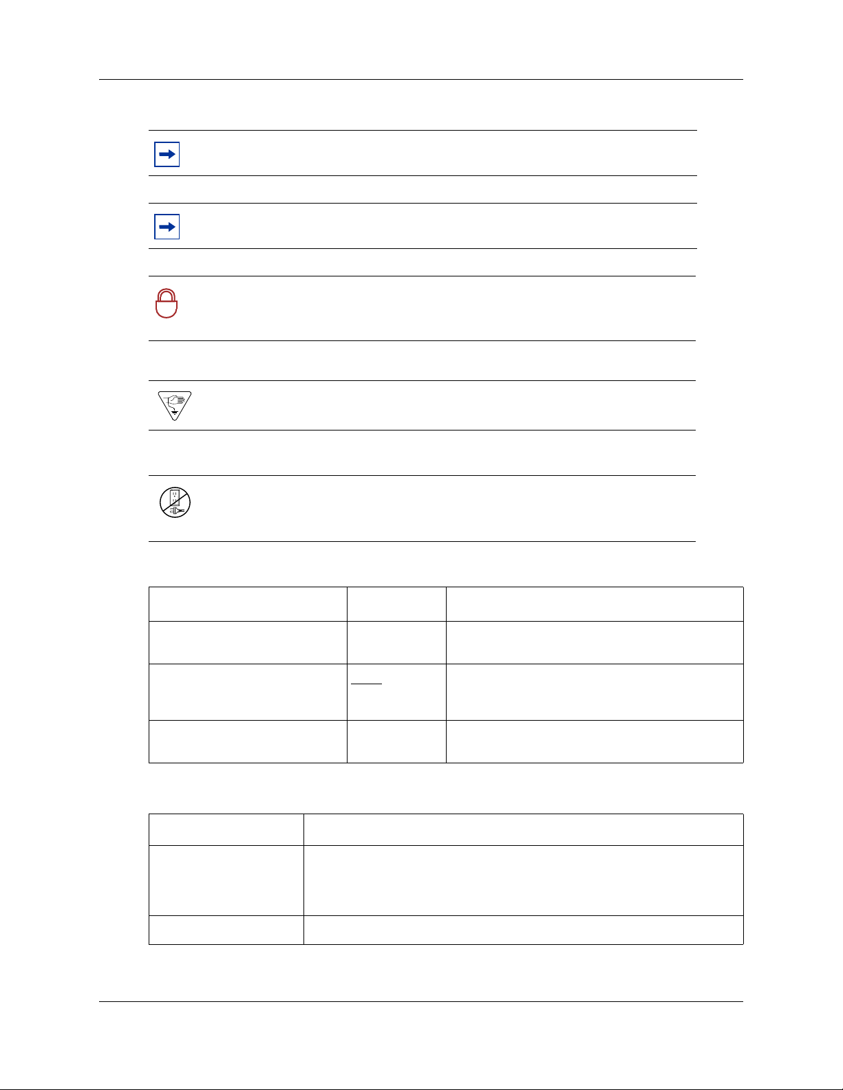
Symbols and text conventions
These symbols highlight critical information for the BCM50 2.0 system.
Caution: Alerts you to conditions where you can damage the equipment.
Danger: Alerts you to conditions where you can get an electrical shock.
Warning: Alerts you to conditions where you can cause the system to fail or work
improperly.
Installation and Maintenance Guide
28 Chapter 1 Getting started
Note: Alerts you to important information.
Tip: Alerts you to additional information that can help you perform a task.
Security Note: Indicates a point of system security where you can change a
default, or where the administrator must decide on the level of security required
!
for the system.
Warning: Alerts you to ground yourself with an antistatic grounding strap
before performing the maintenance procedure.
Warning: Alerts you to remove the BCM50 main unit and expansion unit
power cords from the AC outlet before performing any maintenance
procedure.
These conventions and symbols represent the Business Series Terminal display and dialpad.
Convention Example Used for
Word in a special font (shown in
the top line of the display)
Underlined word in capital letters
(shown in the bottom line of a
two-line display telephone)
Dialpad buttons
Pswd:
PLAY
£
Command line prompts on display telephones.
Display options on two-line display telephones.
Press the button directly below the option on the
display to proceed.
Buttons you press on the dialpad to select a
particular option.
These text conventions are used in this guide to indicate the information described:
Convention Description
bold Courier
text
Indicates command names, options, and text that you must enter.
Example: Use the
Example: Enter
info command.
show ip {alerts|routes}.
italic text Indicates book titles.
NN40020-302

Convention Description
Chapter 1 Getting started 29
plain Courier
text
FEATURE
HOLD
RELEASE
Related publications
This section provides a list of additional documents referred to in this guide. Two publication
types are available: Technical Documents on page 29 and User Guides on page 30.
Technical Documents
System Installation
BCM50 1.0 to BCM50 2.0 Upgrade Guide (NN40020-401)
Installation Checklist and Quick Start Guide (NN40020-308)
Keycode Installation Guide (NN40010-301)
Indicates command syntax and system output (for example, prompts
and system messages).
Example:
Indicates that you press the button with the corresponding icon on the
telephone you are using.
Set Trap Monitor Filters
R2MFC Media Bay Module Installation and Configuration Guide (NN40010-300)
System Programming
Administration Guide (NN40020-600)
Device Configuration Guide (NN40020-300)
Networking Configuration Guide (NN40020-603)
Telset Administration Guide (NN40020-604)
Telephones and Peripherals
Telephony Device Installation Guide (NN40020-309)
Digital Mobility
DECT Deployment and Demonstration Tool
Digital Mobility System Installation and Configuration Guide (NN40010-302)
T7406 Cordless Handset Installation Guide (NN40110-300)
Installation and Maintenance Guide

30 Chapter 1 Getting started
IP Telephony
WLAN IP Telephony Installation and Configuration Guide (NN40050-301)
Call Pilot
CallPilot Manager Set Up and Operation Guide (NN40090-300)
CallPilot Telephone Administration Guide (NN40090-500)
User Guides
There are no references to specific user guides.
How to get help
This section explains how to get help for Nortel products and services.
Getting Help from the Nortel Web site
The best way to get technical support for Nortel products is from the Nortel Technical Support
Web site:
www.nortel.com/support
This site provides quick access to software, documentation, bulletins, and tools to address issues
with Nortel products. More specifically, the site enables you to:
• download software, documentation, and product bulletins
• search the Technical Support Web site and the Nortel Knowledge Base for answers to
technical issues
• sign up for automatic notification of new software and documentation for Nortel equipment
• open and manage technical support cases
Getting Help over the phone from a Nortel Solutions Center
If you don’t find the information you require on the Nortel Technical Support Web site, and have a
Nortel support contract, you can also get help over the phone from a Nortel Solutions Center.
In North America, call 1-800-4NORTEL (1-800-466-7835).
Outside North America, go to the following Web site to obtain the phone number for your region:
www.nortel.com/callus
Getting Help from a specialist by using an Express Routing Code
To access some Nortel Technical Solutions Centers, you can use an Express Routing Code (ERC)
to quickly route your call to a specialist in your Nortel product or service. To locate the ERC for
your product or service, go to:
www.nortel.com/erc
NN40020-302
Loading...