


 Loading...
Installation and Operation Manual
RTU-292
RADIO / TELEPHONE
INTERFACE UNIT
Designed and Manufactured by:
JPS Communications, Inc.
5800 Departure Drive
Raleigh, NC 27616 e-mail: jps@jps.com
JPS P/N 5970-600200 |
Revision 1.62 |
July, 2005 |
|
1 |
JPS Communications, Inc. |

RTU-292 Operations Manual
Warranty
JPS Communications, Inc. warrants its manufactured equipment to be free from defects in materials and workmanship, and to conform to published specifications for a period of 18 months from the date of shipment from the factory or 12 months from installation, whichever occurs first.
JPS warrants its service work performed in connection with this warranty to be free from defects in materials and workmanship for a period of 90 days from the date the work is performed.
If a defect occurs within the warranty period, the buyer shall notify JPS immediately. JPS will repair or replace the equipment at its option, upon return of the equipment; shipping prepaid, to the JPS facility in Raleigh, North Carolina, USA
This warranty does not apply to damage caused by accidents, abuse or improper installation.
NO OTHER WARRANTY, EXPRESSED OR IMPLIED, INCLUDING BUT NOT LIMITED TO THE IMPLIED WARRANTIES OF MERCHANTABILITY AND FITNESS FOR A PARTICULAR PURPOSE, SHALL APPLY.
NOTICE
JPS Communications, Inc. reserves the right to make changes to the equipment and specifications without prior notice.
PROPRIETARY STATEMENT
The information contained in this manual is the property of JPS Communications, Inc. and is intended for the purchaser’s use only. It may not be reproduced without the express written consent of JPS Communications.
Phone: (919) 790-1011 Fax: (919) 790-1456 e-mail: jps@jps.com
5800 Departure Drive Raleigh, NC 27616
JPS Communications, Inc. |
2 |

RTU-292 Operations Manual
Table of Contents
1 GENERAL INFORMATION ...................................................................................................................... |
1-1 |
|
1.1 |
SCOPE .................................................................................................................................................... |
1-1 |
1.2 |
DESCRIPTION....................................................................................................................................... |
1-1 |
1.2.1 |
GENERAL ...................................................................................................................................... |
1-1 |
1.3 |
ASSEMBLIES ........................................................................................................................................ |
1-2 |
1.3.1 |
MAIN BOARD ............................................................................................................................... |
1-2 |
1.3.2 FRONT PANEL SWITCH ASSEMBLIES .................................................................................... |
1-3 |
|
1.3.3 |
OPTIONS INTERFACE BOARD .................................................................................................. |
1-3 |
1.3.4 |
OPTIONS........................................................................................................................................ |
1-5 |
2 |
INSTALLATION.......................................................................................................................................... |
2-1 |
||
|
2.1 |
GENERAL.............................................................................................................................................. |
2-1 |
|
|
2.2 |
UNPACKING AND INSPECTION ....................................................................................................... |
2-1 |
|
|
2.3 |
RESHIPMENT OF EQUIPMENT.......................................................................................................... |
2-1 |
|
|
2.4 |
INSTALLATION OVERVIEW ............................................................................................................. |
2-2 |
|
|
2.5 |
INSTALLATION CONSIDERATIONS ................................................................................................ |
2-2 |
|
|
2.5.1 |
|
FCC PART 68 REGULATIONS .................................................................................................... |
2-2 |
|
2.6 |
POWER REQUIREMENTS................................................................................................................... |
2-4 |
|
|
2.7 |
INPUT POWER SELECTION ............................................................................................................... |
2-4 |
|
|
2.7.1 |
|
LINE VOLTAGE SELECTION ..................................................................................................... |
2-4 |
|
2.7.2 |
|
DC INPUT POWER SELECTION................................................................................................. |
2-4 |
|
2.8 |
CONFIGURING THE RTU-292 ............................................................................................................ |
2-5 |
|
|
2.8.1 |
|
PROGRAMMING MODE SETUP PARAMETERS ..................................................................... |
2-5 |
|
2.8.2 |
|
SETTING TELEPHONE SEND AND RECEIVE LEVELS.......................................................... |
2-5 |
|
2.8.3 |
|
VOX HANGTIME.......................................................................................................................... |
2-7 |
|
2.8.4 |
|
VOX SENSITIVITY....................................................................................................................... |
2-7 |
|
2.8.5 |
|
BALANCED/UNBALANCED RADIO INTERFACE .................................................................. |
2-7 |
|
2.8.6 |
|
RX LINE INPUT IMPEDANCE .................................................................................................... |
2-8 |
|
2.8.7 |
|
DIAL MODE .................................................................................................................................. |
2-8 |
|
2.8.8 |
|
TELEPHONE RING VOLUME ..................................................................................................... |
2-8 |
|
2.8.9 |
|
FULL/HALF DUPLEX RADIO..................................................................................................... |
2-8 |
|
2.8.10 |
SERIAL PORT BAUD RATE........................................................................................................ |
2-9 |
|
|
2.8.11 |
RADIO CONTROL MODE............................................................................................................ |
2-9 |
|
|
2.8.12 |
PASSWORD PROTECTION ....................................................................................................... |
2-10 |
|
|
2.8.13 |
VOICE PROMPTS ....................................................................................................................... |
2-10 |
|
|
2.8.14 |
LOCAL PHONE / LOCAL PHONE RING-THROUGH ............................................................. |
2-10 |
|
|
2.8.15 |
TRANSMIT LEVEL SET-UP MODE.......................................................................................... |
2-11 |
|
|
2.8.16 |
MISCELLANEOUS JUMPERS ................................................................................................... |
2-11 |
|
|
2.9 |
INTERCONNECT INFORMATION ................................................................................................... |
2-11 |
|
|
2.9.1 |
|
TELEPHONE CONNECTION..................................................................................................... |
2-12 |
|
2.9.2 |
|
RADIO CONNECTION ............................................................................................................... |
2-12 |
|
2.9.3 |
|
HANDSET CONNECTOR........................................................................................................... |
2-13 |
|
2.9.4 |
|
TERMINAL BLOCK.................................................................................................................... |
2-14 |
|
2.9.5 |
|
RS-232 CONNECTION................................................................................................................ |
2-15 |
|
2.10 AUDIO LEVEL SETUP AND ADJUSTMENTS ................................................................................ |
2-15 |
||
|
2.10.1 |
SETTING THE TRANSMIT LEVEL........................................................................................... |
2-15 |
|
|
2.10.2 |
SETTING THE RECEIVE LEVEL .............................................................................................. |
2-16 |
|
|
2.11 |
INSTALLATION CHECKLIST........................................................................................................... |
2-24 |
|
|
2.12 OPTIONS INSTALLATION AND CONFIGURATION..................................................................... |
2-24 |
||
3 |
OPERATION ................................................................................................................................................ |
3-1 |
||
|
|
|
3 |
JPS Communications, Inc. |

RTU-292 Operations Manual
3.1 |
GENERAL .............................................................................................................................................. |
3-1 |
|
3.2 FRONT PANEL CONTROLS, INDICATORS AND CONNECTORS ................................................. |
3-1 |
||
3.2.1 |
|
MAIN POWER SWITCH ............................................................................................................... |
3-1 |
3.2.2 |
|
HEADPHONE JACK...................................................................................................................... |
3-1 |
3.2.3 |
|
HANDSET JACK ........................................................................................................................... |
3-1 |
3.2.4 |
|
HANDSET ...................................................................................................................................... |
3-1 |
3.2.5 |
|
SPEAKER ....................................................................................................................................... |
3-1 |
3.2.6 |
|
KEYPAD......................................................................................................................................... |
3-2 |
3.2.7 |
|
SPEAKER VOLUME CONTROL.................................................................................................. |
3-2 |
3.2.8 |
|
PHONES VOLUME CONTROL.................................................................................................... |
3-2 |
3.2.9 |
|
TEL LINE BUTTONS .................................................................................................................... |
3-2 |
3.2.10 |
HANDSET BUTTONS ................................................................................................................... |
3-2 |
|
3.2.11 |
SPEAKER BUTTONS.................................................................................................................... |
3-3 |
|
3.2.12 |
TEL VOX ........................................................................................................................................ |
3-3 |
|
3.2.13 |
AUTO ANS BUTTON.................................................................................................................... |
3-3 |
|
3.2.14 |
AUDIBLE RING BUTTON............................................................................................................ |
3-3 |
|
3.2.15 |
KEY PUSHBUTTON ..................................................................................................................... |
3-3 |
|
3.2.16 |
PEAK LED...................................................................................................................................... |
3-3 |
|
3.3 |
REAR PANEL CONNECTORS............................................................................................................. |
3-4 |
|
3.3.1 |
|
P1 RADIO CONNECTOR.............................................................................................................. |
3-4 |
3.3.2 |
|
J1 TEL LINE ................................................................................................................................... |
3-4 |
3.3.3 |
|
TERMINAL BLOCK...................................................................................................................... |
3-4 |
3.3.4 |
|
J2 LOCAL PHONE CONNECTOR................................................................................................ |
3-4 |
3.3.5 |
|
P2 RS-232 CONNECTOR ............................................................................................................. |
3-4 |
3.3.6 |
|
DC INPUT TERMINAL BLOCK................................................................................................... |
3-4 |
3.3.7 |
|
P1 AC POWER CONNECTOR ..................................................................................................... |
3-4 |
3.4 |
OPERATION .......................................................................................................................................... |
3-5 |
|
3.4.1 |
|
OPERATION OVERVIEW ............................................................................................................ |
3-5 |
3.4.2 |
|
USE OF THE RTU-292 SPEAKER TO MONITOR AUDIO ........................................................ |
3-5 |
3.4.3 |
|
PLACING A TELEPHONE CALL................................................................................................. |
3-5 |
3.4.4 |
|
RECEIVING A TELEPHONE CALL ............................................................................................ |
3-6 |
3.4.5 |
|
PUTTING A TELEPHONE CALL ON HOLD .............................................................................. |
3-6 |
3.4.6 |
|
USING THE HANDSET WITH THE RADIO............................................................................... |
3-6 |
3.4.7 |
|
CONNECTING THE RADIO TO THE TELEPHONE LINE........................................................ |
3-6 |
3.4.8 |
|
MANUAL PHONE PATCH PROCEDURE................................................................................... |
3-7 |
3.4.9 |
|
TRANSMITTER KEYING, HALF DUPLEX SYSTEM ............................................................... |
3-8 |
3.4.10 |
TRANSMITTER KEYING, FULL DUPLEX SYSTEM................................................................ |
3-9 |
|
3.5 |
REMOTE KEY ....................................................................................................................................... |
3-9 |
|
3.6 |
SELF TEST ............................................................................................................................................. |
3-9 |
|
3.7 |
AUTOMATED OPERATION ................................................................................................................ |
3-9 |
|
3.7.1 |
|
TONE PROMPTS ........................................................................................................................... |
3-9 |
3.7.2 |
|
VOICE PROMPTS........................................................................................................................ |
3-10 |
3.7.3 |
|
CALLING THE RTU-292 VIA THE OUTSIDE LINE................................................................ |
3-10 |
3.7.4 |
|
PLACING A CALL IN THE COMMAND MODE:..................................................................... |
3-12 |
3.7.5 |
|
TERMINATING A CALL:........................................................................................................... |
3-12 |
3.7.6 |
|
DTMF CONTROL COMMANDS................................................................................................ |
3-13 |
3.7.7 |
|
RTU-292 PASSWORD PROTECTION ....................................................................................... |
3-16 |
3.7.8 |
|
INACTIVITY DISCONNECT TIMER ........................................................................................ |
3-16 |
3.7.9 |
|
CALLING TIMER ........................................................................................................................ |
3-16 |
3.7.10 |
USING THE RTU-292 SPEED DIAL FEATURE ....................................................................... |
3-17 |
|
3.7.11 |
OPTIONAL 4 WIRE OPERATION ............................................................................................. |
3-18 |
|
3.8 |
FACTORY RESET ............................................................................................................................... |
3-18 |
|
3.9 |
SPEED DIAL RESET ........................................................................................................................... |
3-18 |
|
4 RTU-292 THEORY OF OPERATION ..................................................................................................... |
4-19 |
||
4.1 |
GENERAL ............................................................................................................................................ |
4-19 |
|
JPS Communications, Inc. |
4 |

RTU-292 Operations Manual
4.2 FRONT PANEL BUTTONS AND INDICATORS |
.............................................................................. 4-19 |
||
4.3 |
MAIN BOARD ..................................................................................................................................... |
4-19 |
|
4.3.1 |
|
AUDIO BUS ARRANGEMENT.................................................................................................. |
4-19 |
4.3.2 |
|
TELEPHONE INTERFACE CIRCUITS...................................................................................... |
4-20 |
4.3.3 |
|
RADIO INTERFACE CIRCUITS ................................................................................................ |
4-21 |
4.3.4 |
|
HANDSET/ SPEAKER INTERFACE......................................................................................... |
4-22 |
4.3.5 |
|
DSP MODULE ............................................................................................................................. |
4-22 |
4.3.6 |
|
DSP SOFTWARE......................................................................................................................... |
4-22 |
4.3.7 |
|
POWER SUPPLY......................................................................................................................... |
4-24 |
4.3.8 |
|
CPU............................................................................................................................................... |
4-24 |
4.3.9 |
|
PROMPT TONE GENERATOR .................................................................................................. |
4-25 |
4.4 |
OPTION INTERFACE BOARD .......................................................................................................... |
4-25 |
|
4.5 |
VOICE PROMPT OPTION.................................................................................................................. |
4-25 |
|
4.5.1 |
|
SPEECH PROCESSOR ................................................................................................................ |
4-25 |
4.5.2 |
|
CONTROL PROCESSOR ............................................................................................................ |
4-25 |
4.5.3 |
|
VOICE PROMPT SOFTWARE ................................................................................................... |
4-26 |
4.6 |
LOCAL PHONE OPTION ................................................................................................................... |
4-26 |
|
4.6.1 |
|
INTERFACE CIRCUITRY .......................................................................................................... |
4-26 |
4.6.2 |
|
DIAL/BUSY GENERATORS ...................................................................................................... |
4-26 |
4.6.3 |
|
LOCAL TELEPHONE LINE INTERFACE................................................................................. |
4-26 |
5 REMOTE CONTROL PROTOCOL .......................................................................................................... |
5-1 |
||
5.1 |
GENERAL.............................................................................................................................................. |
5-1 |
|
5.2 RS-232 REMOTE CONTROL OVERVIEW ......................................................................................... |
5-1 |
||
5.3 COMMANDS SENT TO THE RTU-292 ............................................................................................... |
5-1 |
||
5.3.1 |
|
NULL Command ............................................................................................................................ |
5-3 |
5.3.2 |
|
Auto Answer Command.................................................................................................................. |
5-3 |
5.3.3 |
|
Audible Ring Command.................................................................................................................. |
5-3 |
5.3.4 |
|
Date Command................................................................................................................................ |
5-4 |
5.3.5 |
|
Dial Command ................................................................................................................................ |
5-4 |
5.3.6 |
|
Disconnect Command ..................................................................................................................... |
5-5 |
5.3.7 |
|
DTMF Command ............................................................................................................................ |
5-5 |
5.3.8 |
|
Handset Phone Command ............................................................................................................... |
5-6 |
5.3.9 |
|
Handset Radio Command................................................................................................................ |
5-6 |
5.3.10 |
Speaker Phone Command ............................................................................................................... |
5-7 |
|
5.3.11 |
Speaker Radio Command................................................................................................................ |
5-7 |
|
5.3.12 |
Speed Dial Command...................................................................................................................... |
5-8 |
|
5.3.13 |
Tel-Line Phone Command .............................................................................................................. |
5-9 |
|
5.3.14 |
Tel-Line Radio Command............................................................................................................... |
5-9 |
|
5.3.15 |
Time Command............................................................................................................................. |
5-10 |
|
5.3.16 |
Software Version Command ......................................................................................................... |
5-10 |
|
5.4 STATUS RETURNED FROM THE RTU-292 .................................................................................... |
5-11 |
||
5.4.1 |
|
NULL Response............................................................................................................................ |
5-12 |
5.4.2 |
|
Auto Answer Response ................................................................................................................. |
5-12 |
5.4.3 |
|
Call Starting Response .................................................................................................................. |
5-12 |
5.4.4 |
|
Dial Response................................................................................................................................ |
5-13 |
5.4.5 |
|
Disconnect Response .................................................................................................................... |
5-13 |
5.4.6 |
|
DTMF Response ........................................................................................................................... |
5-13 |
5.4.7 |
|
Elapsed Time Response ................................................................................................................ |
5-14 |
5.4.8 |
|
Handset Phone Response .............................................................................................................. |
5-14 |
5.4.9 |
|
Handset Radio Response............................................................................................................... |
5-14 |
5.4.10 |
Speaker Phone Response............................................................................................................... |
5-15 |
|
5.4.11 |
Speaker Radio Response ............................................................................................................... |
5-15 |
|
5.4.12 |
Speed Dial Response..................................................................................................................... |
5-16 |
|
5.4.13 |
Tel-Line Phone Response.............................................................................................................. |
5-16 |
|
5.4.14 |
Tel-Line Radio Response .............................................................................................................. |
5-16 |
|
|
|
5 |
JPS Communications, Inc. |

RTU-292 Operations Manual
|
5.4.15 |
Time/Date Response...................................................................................................................... |
5-17 |
||
|
5.4.16 |
Version Response .......................................................................................................................... |
5-17 |
||
|
5.5 |
CALL PROGRESS RESPONSES FROM THE RTU-292 ................................................................... |
5-18 |
||
|
5.6 |
|
RESPONSE ERROR CODES............................................................................................................... |
5-18 |
|
6 |
MAINTENANCE AND REPAIR .............................................................................................................. |
6-19 |
|||
|
6.1 |
|
GENERAL ............................................................................................................................................ |
6-19 |
|
|
6.2 |
|
PREVENTIVE MAINTENANCE ........................................................................................................ |
6-19 |
|
|
6.3 |
|
REPAIR OR REPLACEMENT ............................................................................................................ |
6-19 |
|
|
6.3.1 |
|
GENERAL PRECAUTIONS AND NOTES................................................................................. |
6-19 |
|
|
6.4 |
|
ALIGNMENT ....................................................................................................................................... |
6-19 |
|
|
6.5 |
|
PERFORMANCE TESTING................................................................................................................ |
6-19 |
|
|
6.5.1 |
|
TEST EQUIPMENT REQUIRED ................................................................................................ |
6-19 |
|
|
6.5.2 |
|
HYBRID BALANCE MEASUREMENT..................................................................................... |
6-20 |
|
|
6.5.3 |
|
VOX SENSITIVITY MEASUREMENT...................................................................................... |
6-23 |
|
7 |
RTU-292 OPTIONS ...................................................................................................................................... |
7-1 |
|||
|
7.1 |
|
GENERAL .............................................................................................................................................. |
7-1 |
|
|
7.1.1 |
|
Special Software Versions............................................................................................................... |
7-1 |
|
|
7.2 |
|
VOICE PROMPT OPTION .................................................................................................................... |
7-2 |
|
|
7.2.1 |
|
INSTALLATION AND CONFIGURATION................................................................................. |
7-2 |
|
|
7.2.2 |
|
OPERATION .................................................................................................................................. |
7-2 |
|
|
7.3 |
|
LOCAL PHONE OPTION...................................................................................................................... |
7-4 |
|
|
7.3.1 |
|
LOCAL PHONE OPTION INSTALLATION AND CONFIGURATION..................................... |
7-4 |
|
|
7.3.2 |
|
LOCAL PHONE OPTION OPERATION ...................................................................................... |
7-5 |
|
|
7.4 |
|
VMM-100 OPTION ................................................................................................................................ |
7-6 |
|
|
7.4.1 |
|
VMM-100 Hardware ....................................................................................................................... |
7-6 |
|
|
7.4.2 |
|
VMM-100 Software ........................................................................................................................ |
7-7 |
|
|
7.4.3 |
|
VMM-100 INSTALLATION AND CONFIGURATION............................................................... |
7-7 |
|
|
7.5 |
|
DTMF ACCESS OPTION .................................................................................................................... |
7-11 |
|
|
7.5.1 |
Initiate Call Via Attention Signal .................................................................................................. |
7-11 |
||
|
7.5.2 |
|
RTU-292 Response to Attention Signal ........................................................................................ |
7-11 |
|
|
7.5.3 |
Radio Caller Provides Calling Directions...................................................................................... |
7-11 |
||
|
7.5.4 |
RTU-292 Plays Back Phone Number & Prompts for Confirmation.............................................. |
7-11 |
||
|
7.5.5 |
|
RTU-292 Places the Call ............................................................................................................... |
7-11 |
|
|
7.5.6 |
|
After the Call Begins ..................................................................................................................... |
7-12 |
|
|
7.6 |
SQUELCH BREAK ACCESS OPTION............................................................................................... |
7-13 |
||
|
7.6.1 |
Initiate Call Via Attention Signal .................................................................................................. |
7-13 |
||
|
7.6.2 |
RTU-292 Response to Attention Signal ........................................................................................ |
7-13 |
||
|
7.6.3 |
RTU-292 Prompts for Confirmation ............................................................................................. |
7-13 |
||
|
7.6.4 |
RTU-292 Places the Call ............................................................................................................... |
7-13 |
||
|
7.6.5 |
After the Call Begins ..................................................................................................................... |
7-13 |
||
|
7.7 |
THE CALL LOGGING OPTION ......................................................................................................... |
7-14 |
||
|
7.7.1 |
Checking The Time And Date....................................................................................................... |
7-14 |
||
|
7.7.2 |
|
Setting The Time ........................................................................................................................... |
7-14 |
|
|
7.7.3 |
|
Setting The Date............................................................................................................................ |
7-14 |
|
|
7.7.4 |
|
Call Logging.................................................................................................................................. |
7-14 |
|
|
7.8 |
|
RADIO CONTROL OPTION............................................................................................................... |
7-15 |
|
|
7.8.1 |
CONTROLLING THE RADIO VIA THE RTU-292 FRONT PANEL KEYPAD....................... |
7-15 |
||
8 |
SCHEMATIC DIAGRAMS ......................................................................................................................... |
8-1 |
|||
|
8.1 |
|
GENERAL .............................................................................................................................................. |
8-1 |
|
9 |
INDEX |
............................................................................................................................................................ |
9-1 |
||
JPS Communications, Inc. |
6 |

RTU-292 Operations Manual
List Of Figures
FIGURE 2-1 OUTLINE DIMENSIONS ................................................................................................................... |
2-18 |
|
FIGURE 2-2 CONTROL AND CONNECTOR LOCATIONS ....................................................................................... |
2-19 |
|
FIGURE 2-3 LOCATION OF INTERNAL OPTION SETTINGS .................................................................................. |
2-20 |
|
FIGURE 2-4 INTERNAL OPTION SETTING DETAILS ............................................................................................ |
2-21 |
|
FIGURE 2-5 AUDIO INTERFACE WIRING DIAGRAM ........................................................................................... |
2-22 |
|
FIGURE 2-6 |
INTERFACE DETAILS ...................................................................................................................... |
2-23 |
FIGURE 6-1 HYBRID BALANCE TEST SET-UP.................................................................................................... |
6-21 |
|
FIGURE 6-2 |
VOX SENSITIVITY TEST SET-UP ................................................................................................... |
6-23 |
FIGURE 7-1 VOICE PROMPT OPTION INSTALLATION ........................................................................................... |
7-3 |
|
FIGURE 7-2 LOCAL PHONE OPTION INSTALLATION............................................................................................. |
7-5 |
|
FIGURE 7-3 |
VMM-100 OPTION INSTALLATION .................................................................................................. |
7-8 |
FIGURE 8-1 FRONT PANEL SCHEMATIC............................................................................................................... |
8-1 |
|
FIGURE 8-2 MAIN BOARD SCHEMATIC ............................................................................................................... |
8-1 |
|
FIGURE 8-3 |
DSP MODULE .................................................................................................................................. |
8-1 |
FIGURE 8-4 OPTION INTERFACE BOARD ............................................................................................................. |
8-1 |
|
FIGURE 8-5 VOICE PROMPT OPTION BOARD ....................................................................................................... |
8-1 |
|
FIGURE 8-6 LOCAL PHONE OPTION BOARD ........................................................................................................ |
8-1 |
|
FIGURE 8-7 |
VMM-100 OPTION BOARD.............................................................................................................. |
8-1 |
7 |
JPS Communications, Inc. |

RTU-292 Operations Manual
List of Tables
TABLE 1-1 |
EQUIPMENT AND ACCESSORIES SUPPLIED .................................................................................... |
1-4 |
TABLE 1-2 |
OPTIONAL EQUIPMENT - NOT SUPPLIED ........................................................................................ |
1-5 |
TABLE 1-3 |
RTU-292 SPECIFICATIONS....................................................................................................... |
1-6 |
TABLE 2-1 |
RTU-292 FACTORY DEFAULT SETTINGS....................................................................................... |
2-3 |
TABLE 2-2 |
RECOMMENDED PHONE LINE SETTINGS ........................................................................................ |
2-6 |
TABLE 2-3 |
TELEPHONE SEND/RECEIVE LEVELS .............................................................................................. |
2-6 |
TABLE 2-4 |
VOX HANGTIME .............................................................................................................................. |
2-7 |
TABLE 2-5 |
VOX SENSITIVITY ........................................................................................................................... |
2-7 |
TABLE 2-6 |
DIAL MODE ...................................................................................................................................... |
2-8 |
TABLE 2-7 |
FULL/HALF DUPLEX......................................................................................................................... |
2-9 |
TABLE 2-8 |
BAUD RATE...................................................................................................................................... |
2-9 |
TABLE 2-9 |
RADIO CONTROL MODE ................................................................................................................... |
2-9 |
TABLE 2-10 |
PASSWORD PROTECTION.............................................................................................................. |
2-10 |
TABLE 2-11 |
VOICE PROMPTS ENABLE ............................................................................................................. |
2-10 |
TABLE 2-12 |
LOCAL PHONE ENABLE ................................................................................................................. |
2-11 |
TABLE 2-13 |
LOCAL PHONE RINGTHROUGH...................................................................................................... |
2-11 |
TABLE 2-14 |
TX LEVEL SET-UP MODE .............................................................................................................. |
2-11 |
TABLE 2-15 |
J1 - TEL LINE (RJ-11C)............................................................................................................. |
2-12 |
TABLE 2-16 |
P1-RADIO (DB-9 MALE) ............................................................................................................ |
2-13 |
TABLE 2-17 |
J7 - HANDSET (RJ12C JACK)................................................................................................... |
2-13 |
TABLE 2-18 |
TERMINAL BLOCK (6 POSITION).................................................................................................... |
2-14 |
TABLE 2-19 |
P2 – RS-232 CONNECTOR (DB-9 MALE) ................................................................................... |
2-15 |
TABLE 2-20 |
INSTALLATION CHECKLIST............................................................................................................. |
2-24 |
TABLE 3-1 |
STANDARD DTMF OPERATIONAL COMMANDS ............................................................................ |
3-14 |
TABLE 3-2 |
PROGRAMMING MODE DTMF COMMANDS .................................................................................. |
3-15 |
TABLE 5-1 |
COMMAND SUMMARY...................................................................................................................... |
5-2 |
TABLE 5-2 |
RESPONSE SUMMARY ................................................................................................................... |
5-11 |
TABLE 5-3 |
CALL PROGRESS RESPONSES...................................................................................................... |
5-18 |
TABLE 5-4 |
RESPONSE ERROR CODES ........................................................................................................... |
5-18 |
TABLE 6-1 |
FAULT ANALYSIS ........................................................................................................................... |
6-24 |
TABLE 7-1 |
RTU-292 OPTIONS.......................................................................................................................... |
7-1 |
TABLE 7-2 |
VOICE PROMPTS ENABLE ............................................................................................................... |
7-2 |
TABLE 7-3 |
LOCAL PHONE ENABLE ................................................................................................................... |
7-4 |
TABLE 7-4 |
LOCAL PHONE RINGTHROUGH........................................................................................................ |
7-4 |
TABLE 7-5 |
LOCAL PHONE DTMF COMMANDS................................................................................................. |
7-5 |
TABLE 7-6 |
VMM-100 SPECIFICATIONS ..................................................................................................... |
7-9 |
TABLE 7-7 |
VMM-100 I/O CONNECTOR INFORMATION (P9) ............................................................... |
7-10 |
TABLE 7-8 |
VMM-100 SWITCH FUNCTIONS.................................................................................................... |
7-10 |
TABLE 7-9 |
DTMF RADIO CONTROL COMMANDS........................................................................................... |
7-16 |
JPS Communications, Inc. |
8 |

RTU-292 Operations Manual
|
Glossary |
|
|
Adaptation |
The process whereby the RTU-292 DSP algorithms detect reflected signal information in a |
|
connected line and tune the DSP hybrid for a broadband null with minimum reflection. |
|
|
COR |
Carrier Operated Relay - A receiver signal that gives a positive indication that a carrier or signal |
|
is being received and that the receiver is unsquelched. Same as COS. |
|
|
COS |
Carrier Operated Squelch - See COR. |
|
|
CTCSS |
Continuous Tone Controlled Squelch System. A squelch system using EIA Standardized sub- |
|
audible tones in the 67Hz to 250Hz frequency range. An FM squelch which opens only when |
|
the proper sub-audible tone is present. |
|
|
DIP Switch |
Dual In-Line Package Switch (Also “dipswitch”)- A multi-unit switch that fits into a standard |
|
DIP integrated circuit footprint. It usually contains eight or ten individual switches. |
|
|
DTMF |
Dual Tone Multi Frequency - The standard touch-tone telephone dialing method. |
|
|
DSP |
Digital Signal Processing (or Processor). |
EIA |
Electronic Industries Association. |
|
|
Full Duplex |
A communications system that can operate in transmit mode and receive mode simultaneously, |
|
with different frequencies for transmit and receive. See also Half Duplex and Simplex. |
|
|
Half Duplex |
A communications system that uses different frequencies for transmit and receive operation, but |
|
can not transmit and receive at the same time. See also Full Duplex and Simplex. |
|
|
Hangtime |
A system with hangtime will remain in the transmit mode for the duration of the set hangtime |
|
beyond the time indicated by any keying inputs. The hangtime prevents transmitter unkey |
|
during brief pauses in the transmission. |
|
|
Key |
To key a transmitter means to cause it to transmit. |
LED |
Light Emitting Diode. |
|
|
LMR |
Land Mobile Radio. |
|
|
Mute |
To quiet or inhibit audio. |
PCB |
Printed Circuit Board. |
|
|
PTT |
Push-to-Talk. An active PTT signal causes a transmitter to key. |
|
|
RX |
Receiver or Receiving. |
Simplex |
A communications system that uses the same frequencies for both transmit and receive |
|
operation. A simplex system can obviously not transmit and receive simultaneously. See also |
|
Full Duplex and Half Duplex. |
|
|
SNR |
Signal-to-Noise Ratio. |
|
|
Squelch |
A means of detecting audio and causing some action when it is present, such as keying a |
|
transmitter or unmuting an audio path. |
|
|
TX |
Transmit or Transmitter. |
|
|
VMR |
Voice Modulation Recognition. A type of squelch, which is activated only by spoken words and |
|
not by tones, noise, or other audio information. |
|
|
VOX |
Voice Operated Xmit (Transmit). A circuit or algorithm that causes a transmitter to key or some |
|
other action when voice or other signal is present. This squelch type is activated by any audio |
|
signal, and is not restricted to voice only. |
|
|
9 |
JPS Communications, Inc. |

RTU-292 Operations Manual
This page intentionally left blank.
JPS Communications, Inc. |
10 |
RTU-292 Operations Manual
1 General Information
1.1 SCOPE
This instruction manual provides the information necessary to install, operate, repair and maintain the RTU-292 Radio/Telephone Interface.
1.2 DESCRIPTION
1.2.1GENERAL
The RTU-292 Radio/Telephone Interface Unit will provide a trouble-free automatic connection between a radio system and telephone or other two-wire line. The unit is suited for use with HF, VHF, UHF or satellite systems and is applicable to full or half-duplex modes. The RTU292 incorporates a full-featured telephone set and monitor speaker. Flexible switching allows many operating scenarios.
The RTU-292 replaces the JPS Communications RTU-282. The RTU-292 contains all of the features and capabilities of the RTU-282, along with some major improvements. The new DSP used in the RTU-292 allows improved Call Progress Detection. Additional circuitry on the Main Board provides the ability to detect line reversal when a telephone caller hangs up the phone, allowing immediate call termination when used with phone systems that have Reverse Battery Signaling. A new standard feature with the RTU-292 is RS-232 control of the unit. A new optional feature is DTMF Access of the system via radio.
A front panel keypad allows DTMF or Pulse dialing and the built-in handset is pushbuttonselectable for communication with either the telephone or the radio. Since the telephone may place and receive calls, the operator can quickly and easily establish a phone patch connection. When used in the manual mode, the RTU-292 patches a telephone into a radio link by essentially the same method as with a conventional phone patch; the quality of the patch, however is greatly improved. First, a radio-to-radio link is established. Then, using the telephone in the RTU-292, the operator places a phone call to the distant telephone that will be patched into the radio link. Once the telephone-to-telephone link is made, the operator simply pushes a front panel pushbutton. The RTU-292 adapts to the phone line, and the distant phone becomes part of a telephone-to-radio-to-radio communications link. Once this link is established, the operator may communicate with either party using the RTU-292’s handset, and may monitor both sides of the conversation with the speaker.
The RTU-292 uses a unique adaptive hybrid implemented with a DSP (Digital Signal Processor) to eliminate conventional VOX and hybrid adjustments for a quick and simple setup. The unit works by measuring the characteristics of the telephone line. A short burst of white noise is placed on the telephone line. During this burst, the adaptive hybrid in the unit measures the signal reflected from the phone line and adapts the RTU-292 to the impedance of the phone line, minimizing the reflected signal. This achieves a broadband hybrid balance on the reactive phone line. This is simply not possible with any type of conventional active or passive hybrid. Not only is a deep, broadband null provided, but also the action is completely
1-1 |
JPS Communications, Inc. |

RTU-292 Operations Manual
automatic. The unit will continuously adapt to changing line conditions, making operation insensitive to line impedance changes.
In the Automated Operations mode, the RTU-292 combines the unique features of its adaptive DSP hybrid with fully unmanned auto-dial/auto-answer capability. In its standard configuration, the unit uses tone prompts to signal the remote user of the operations that must be performed to control the unmanned radio station. The addition of a Voice Prompt Option supplies a large number of spoken prompts to simplify control. The Local Phone Option allows a standard telephone set to be plugged into the rear panel of the RTU-292; this local phone may then be used in place of the unit's keypad and handset.
Input and output levels are internally adjustable to accommodate all types of radio systems. A set-up mode allows the adjustment of the RTU-292 receiver and transmitter signal levels without any external test equipment.
The unit will interface all types of two-wire lines, such as normal dial-up lines, dedicated lines, or twisted-pair field wire. Although the output impedance is fixed at 600 Ohms, the adaptive hybrid in the unit will give excellent hybrid balance regardless of the impedance of the line connected to the unit.
The unit operates from 115 or 230 VAC, 47 to 63 Hz, or from +12 or +24/+28 VDC nominal; the +12VDC range extends from +11 to +15 VDC, while the +24/+28 VDC range extends from +22 to +30 VDC. It is packaged in a rugged enclosure measuring 3.5"H x 19"W x 12"D. All inputs and outputs, including those for power, are filtered or protected as appropriate to enable the RTU-292 to meet the requirements of FCC Part 15 rules for a Class A Digital Device.
1.3 ASSEMBLIES
The standard RTU-292 contains five PC board assemblies; the main board (with plug-on adaptive hybrid DSP board), three front panel switch PC board assemblies, and the Options Interface Board, which is mounted in the Options Tray where other option boards may be installed. Mounted on the front panel along with the switchboards are a speaker, control potentiometers, phone jack and handset jack. The various I/O connectors and the DC power input connector are accessible via the rear panel.
1.3.1 MAIN BOARD
The main board has six general sections of circuitry: the Telephone Interface section, Handset/Speaker Interface section, Radio Interface section, DSP section, CPU section, and Power Supply section. These are described briefly in the following paragraphs. Refer to the RTU-292 block diagram along with the text. (The power supply and DSP sections are not shown in the block diagram, refer to Section 4 for more details.)
1.3.1.1 Telephone Interface
The Telephone Interface Section has the amplifiers that drive and receive audio from the phone line. This section also contains the DSP hybrid (which is detailed in Section 4 of this manual), interfaced with the keypad. A tone ringer generates a warble audio tone when ring voltage is received.
JPS Communications, Inc. |
1-2 |

RTU-292 Operations Manual
1.3.1.2 Handset/Speaker Interface
The Handset/Speaker Interface Section contains the speaker pre-amp and driver, the headphone pre-amp and driver. Audio gates controlled by the front panel switches route the audio to the speaker and handset microphone preamplifier and ALC (Automatic Level Control) circuit.
1.3.1.3 Radio Interface
The Radio Interface Section consists of operational amplifier circuits that handle the audio interfaces between the RTU-292 and the radio. The amplifiers provide gain adjustability to accommodate various input and output levels, and also provide impedance transformation and output drive capability. Audio gates controlled by the front panel switches and the CPU route the audio as desired by the operator.
1.3.1.4 DSP Module
The plug-in Digital Signal Processor (DSP) module is the heart of the unit, as the adaptive hybrid is implemented with the DSP. From a hardware standpoint, the DSP section consists of a DSP chip interfaced with dual analog interface ICs, static RAM for audio storage and delay, and a program flash memory IC.
From a software standpoint, the following functions are implemented in software in the DSP section: the adaptive hybrid, the VOX, an audio peak detector, the noise generator for measuring the telephone line characteristics, an audio delay and the transmit setup tone generator.
1.3.1.5 CPU Section
This section contains the microprocessor and program software that controls all operations of the RTU-292. Various I/O devices read external inputs and the front panel controls. The inputs are processed and audio gates, front panel LEDs, audio prompts, etc., are controlled accordingly.
1.3.1.6 Power Supply Section
The power supply in the RTU-292 is a quiet and reliable passive regulator type. It furnishes regulated voltages of +12V, -12V, +5V and -5V to the unit.
1.3.2 FRONT PANEL SWITCH ASSEMBLIES
There are three separate front panel switch assemblies that contain the pushbutton switches and LED indicators for the RTU-292. Each of these assemblies contains a different complement of components as required by its function. Signals from the switches are read by the CPU circuitry on the main board. The processor then routes audio signals and lights the front panel LEDs according to the pushbutton commands.
1.3.3 OPTIONS INTERFACE BOARD
This board, located on the Options Tray above the main board, contains the connectors used to interface the main board to the various option boards that may be assembled to the Options Tray.
1-3 |
JPS Communications, Inc. |

RTU-292 Operations Manual
|
Table 1-1 |
Equipment and Accessories Supplied |
||
|
|
|
|
|
Qty |
|
Part Number |
Item |
|
1 |
|
5970-600000 |
RTU-292 Standard |
|
|
|
|
|
|
1 |
|
5970-600200 |
Operation & Maintenance Manual |
|
|
|
|
|
|
1 |
|
5970-600150 |
Accessory Kit |
|
Accessory Kit |
|
|
|
|
Consists of: |
|
|
||
Qty |
|
Part Number |
Item |
|
1 |
|
0150-200000 |
Handset, PTT, black |
|
|
|
|
|
|
1 |
|
0313-037770 |
Cable, misc., power w/3-wire connector |
|
|
|
|
|
|
1 |
|
0313-060000 |
Cord, coiled, black (for handset) |
|
|
|
|
|
|
2 |
|
0360-009000 |
Connector, cable, DB-9 receptacle |
|
|
|
|
|
|
2 |
|
0650-005100 |
Fuse, 3AG, 1/2A, slow blow |
|
|
|
|
|
|
2 |
|
0650-010100 |
Fuse, 3AG, 1A, slow blow |
|
|
|
|
|
|
2 |
|
0827-000001 |
HW, clamp, cable, for DB-9 connector |
|
|
|
|
|
|
1 |
|
0827-102401 |
HW, Telephone Hanger; may be attached to front panel |
|
|
|
|
|
(holes provided) |
|
|
|
|
|
9 |
|
0833-063205 |
HW, screw, flat head, 6-32 x 5/16”, 100 degrees, |
|
|
|
|
|
(spares for top cover mounting) |
|
|
|
|
|
5 |
|
0837-103200 |
HW, screw, truss head, #10-32x3/8, for mounting unit front |
|
|
|
|
|
panel to rack (includes one spare) |
|
|
|
|
|
5 |
|
0848-100001 |
HW, washer, flat, nylon (#10 by ½” diameter by 1/16” |
|
|
|
|
|
thick), for mounting unit front panel to rack (includes one |
|
|
|
|
spare) |
JPS Communications, Inc. |
1-4 |

RTU-292 Operations Manual
1.3.4OPTIONS
RTU-292 options include the: The Voice Prompt Option, which gives verbal prompts to the user as an aid in all aspects of unit operation; The Local Phone Option, which allows a DTMF telephone set to be plugged into the unit, allowing control and access from the phone set; and the VMM-100 module, used to add VMR (Voice Modulation Recognition) and DSP noise reduction capability. Among the Software Options are the Squelch Break Access Option, which allows a radio to contact the system via series of squelch breaks and the DTMF Access Option, which allows a radio user to contact the system via a DTMF keypad. Other Software Options include Call Logging and Remote Control of an URC-200 radio. Various spares kits are also available. The STU-III option allows a STU-III phone to be connected to the RTU292. This allows an encrypted STU-III conversation to be decrypted at the RTU-292. The decrypted signal is patched into the connected radio system.
Table 1-2 |
Optional Equipment - Not Supplied |
|||
|
|
|
|
|
Item |
|
JPS P/N |
|
Description |
|
|
|
|
|
Depot Spares Kit |
5970-691000 |
|
Spares for 3 to 5 RTU-292s |
|
|
|
|
|
|
Spare PC Board Kit |
5970-692000 |
|
Spare Boards for 1 unit |
|
|
|
|
|
|
Spare Parts Kit |
5970-693000 |
|
Spares for one RTU-292 |
|
|
|
|
|
|
Local Phone Option |
5930-596000 |
|
Allows remote operation of the RTU-292 through the use of |
|
|
|
|
|
a standard telephone set connected directly to the RTU-292 |
|
|
|
|
Local Phone port. (Telephone set and cable not supplied.) |
|
|
|
|
|
DTMF Telephone Set |
5930-599000 |
|
Telephone set for use with the Local Phone Option |
|
|
|
|
|
|
Voice Prompt Option |
5930-595000 |
|
Standard Version (English, female voice) |
|
|
|
|
|
|
VMM-100 Option |
5930-591100 |
|
Provides DSP Voice Modulation Recognition squelch and/or |
|
|
|
|
|
DSP Noise Reduction to the radio RX input. |
|
|
|
|
|
STU-III Option |
5960-796000 |
|
Allows connection to a STU-III phone |
|
|
|
|
|
|
Rack Slides Kit |
5930-594000 |
|
1 set slides and hardware to rack-mount one RTU-292. |
|
|
|
|
|
|
|
|
|
Software Options |
|
|
|
|
|
|
Call Logging S/W Option |
5970-791500 |
|
Provides record of calls via RS-232 interface. |
|
|
|
|
|
|
Radio Control Option |
5970-795000 |
|
Provides remote control of URC-200 radio via RS-232 int. |
|
|
|
|
|
|
Squelch Break Access |
5970-791300 |
|
Allows radio connection via series of squelch breaks |
|
|
|
|
|
|
DTMF Access Option |
5970-799000 |
|
Allows radio connection via DTMF keypad. |
|
|
|
|
|
|
|
|
|
|
|
1-5 |
JPS Communications, Inc. |

RTU-292 Operations Manual
Table 1-3 |
RTU-292 SPECIFICATIONS |
|
|
TELEPHONE LINE INTERFACE (J2, Male DB-9 Connector) |
|
Output & Input Levels to Phone Line |
Nominally -12 dBm. (Adjustable -21 to 0 dBm in 3 dB steps). |
Frequency Response |
+2 dB, 300 to 3200 Hz. |
Output Impedance to Phone Line |
600 Ohm . |
VOX Sensitivity |
16 +2 dB Below Phone Line Input Level Setting. |
|
(-25 dBm @ -9 dBm Level Setting, for example) |
VOX Hang Time |
0.6 Second or 2.0 Seconds, (Internally Settable). |
Hybrid Balance/Adaptation Speed |
-30 dB over 300 to 3200 Hz BW within 1.25 Sec.; measured with |
(into 600 Ohm) |
white noise source. |
Ultimate Hybrid Balance (into 600 Ohm) |
-50 dB typical over 300 to 3200 Hz BW; measured with a single |
|
tone. |
Hybrid Impedance Matching Capability |
0 to 10k Ohm Complex Impedance. |
Phone Line Connections |
RJ11C Connector (J1) and screw terminals on rear panel term |
|
block. |
RADIO INTERFACE (J1, Male DB-9 Connector) |
|
Input Impedance |
Balanced or Unbalanced 600 Ohm or Unbalanced 47K Ohm. |
Input Level |
-40 to +10 dBm, Internally Adjustable. |
Output Impedance |
600 Ohm balanced. |
Output Level |
-40 to +10 dBm, Internally Adjustable |
Frequency Response |
300 to 3200 Hz + 2 dB. |
Key Relay Output |
Low Level Relay Contacts, 60VA max., Switching Speed: 5 msec. |
TELEPHONE |
|
Handset (RJ12C Jack) |
Electret microphone, dynamic receiver. |
Dialing Modes |
DTMF, Pulse at 10 pps |
Pulse Dial Make/Break Ratio |
40/60. |
Dialing Keypad |
3x4, Standard Telephone Layout. |
GENERAL |
|
Microphone Interface |
ALC (Automatic Level Control) with 30 dB dynamic range. |
Headphone Interface |
Drives high, medium, or low impedance headphones. |
Phones Jack (monaural) |
Delivers NLT 10mW into 600-Ohm headphones. |
Speaker Driver Power |
4W min @ 10% Distortion. |
Internal Speaker |
3 inch square, 3.2 Ohms. |
Indicators |
Peak Level, Keyed, and Indicator for each pushbutton. |
Front Panel Controls |
Power Switch, Dialing Keypad, Speaker and Handset Volume |
|
Controls, Pushbuttons: Tel Line/Phone, Tel Line/Radio, Off, |
|
Handset/Phone, Handset/Radio, Speaker/Phone, Speaker/Radio, |
|
Tel VOX, Manual Key, Auto Answer, Audible Ring. |
AC Input Power |
115 or 230 VAC +/- 15%, 47-63 Hz, 20 VA typical, 50 VA max. |
DC Input Power |
+11 to +15VDC or +22 to +30VDC, 1 A Maximum. |
Size |
3.5"H x 19"W x 10"D (8.9 x 48.3 x 25.4 cm) |
Weight |
12 lbs. (5.5 kg). |
ENVIRONMENTAL |
|
Operating Temperature |
-200 C to +550 C. |
Storage Temperature |
-400 C to +850 C. |
Humidity |
Up to 95% @ 550 C. |
Shock |
MIL-STD-810D, method 516.3 procedure VI. |
Vibration |
MIL STD 810D, method 514.3 Category I. |
JPS Communications, Inc.

RTU-292 Operations Manual
2 Installation
2.1 GENERAL
This section provides the instructions for unpacking, inspection, installation and set-up. Also included are directions for reshipment of damaged parts or equipment.
2.2 UNPACKING AND INSPECTION
After unpacking the unit, retain the carton and packing materials until the contents have been inspected and checked against the packing list. If there is a shortage or any evidence of damage, do not attempt to use the equipment. Contact the carrier and file a shipment damage claim. A full report of the damage should also be reported to the JPS Customer Service Department. The following information should be included in the report:
1.Order Number
2.Equipment Model and Serial Numbers
3.Shipping Agency
4.Date(s) of Shipment
The JPS Customer Service Department can be reached by phone at (919) 790-1011, by fax at (919) 790-1456. Upon receipt of this information, JPS will arrange for repair or replacement of the equipment.
2.3 RESHIPMENT OF EQUIPMENT
If it is necessary to return the equipment to the manufacturer, a Returned Material Authorization (RMA) number must first be obtained from JPS. This number must be noted on the outside of the packing carton and on all accompanying documents. When packing the unit for reshipment, it is best to use the original packaging for the unit; if this is not possible, special attention should be given to providing adequate packing material around connectors and other protrusions, such as front panel controls. Rigid cardboard should be placed at the corners of the unit to protect against corner damage during shipment. Failure to protect the corners of the front panel causes the most common type of shipping damage experienced on returned equipment.
Shipment should be made prepaid consigned to:
JPS Communications, Inc. Customer Service Department 5720M Capital Blvd.
Raleigh, North Carolina 27616 USA
Plainly mark with indelible ink all mailing documents as follows:
U.S. GOODS RETURNED FOR REPAIR
2-1 |
JPS Communications, Inc. |

RTU-292 Operations Manual
Mark all sides of the package:
FRAGILE - ELECTRONIC EQUIPMENT
Inspect the package prior to shipment to be sure it is properly marked and securely wrapped.
2.4 INSTALLATION OVERVIEW
Follow these four steps to properly install the RTU-292:
1.Provide mechanical mounting for the unit. (Rack slides or shelves are required for 19" rack mounting)
2.Provide the proper primary power for the unit.
3.Interconnect the unit with the radio and system as appropriate.
4.Check Section 2.8 to ensure that the unit is adjusted and configured as desired.
The RTU-292 is then ready to begin normal operation.
2.5 INSTALLATION CONSIDERATIONS
Careful attention to the following installation suggestions should result in the best unit/system performance. Figure 2.1 provides overall unit dimensions.
The RTU-292 must be installed in a structure that provides both protection from the weather and assurance of ambient temperatures between -20 and +55 degrees C. Since the unit is neither splashproof nor corrosion resistant, it must be protected from exposure to salt spray. When the unit is mounted in a cabinet with other heat-generating equipment, the use of a rack blower is suggested to keep the cabinet interior temperature rise to a minimum.
NOTE
Before actually installing the unit, read Section 2.8 to determine if any internal configuration options must be changed that would necessitate removal of the unit’s top cover.
The RTU-292 Radio/Telephone Interface is designed to be mounted in a standard EIA 19" wide rack by means of chassis slides (may be ordered from JPS) or on an L-bracket shelf. The unit weighs too much to be installed in a rack supported only by the front panel ears. Screws are provided in the accessory kit for securing the unit to the rack via the front panel.
Included in the Accessory Kit is a handset hanger; this hanger may be assembled to the unit’s front panel. Use the screws located below the logo and unit name. The hanger may also be assembled to the side of an equipment rack or elsewhere as desired.
2.5.1FCC PART 68 REGULATIONS
The RTU-292 has been designed to comply with FCC Part 68 regulations regarding equipment connected to telephone lines, but is not officially certified. If tested compliance to FCC Part 68 is required, external equipment can be installed between the RTU-292 and the telephone line to provide compliance.
JPS Communications, Inc. |
2-2 |

RTU-292 Operations Manual
Table 2-1 RTU-292 Factory Default Settings
This table describes the settings of all RTU-292 internal adjustments and switch positions as set when the unit is shipped.
Feature / Function |
Adjustment |
Default Setting |
|
|
|
Telephone Send and Receive Levels |
SW2-1, 2,3 |
-9 dBm |
Dial Mode |
SW1-4 |
DTMF |
|
|
|
VOX Sensitivity |
SW2-4, 5 |
Medium |
|
|
|
VOX Hangtime |
SW2-6 |
Long (2 second hangtime) |
Full/Half Duplex |
SW2-8 |
Half Duplex |
|
|
|
RX Audio Interface |
JP1, JP2 |
600 Ohms, Balanced |
|
|
|
TX Audio Interface |
JP3 |
600 Ohms, Balanced |
|
|
|
Internal Audio Potentiometers |
R156, Ring Volume |
Midrange |
|
|
|
|
R116, RX Lvl Adj |
0 dBm input |
|
R133, TX Lvl Adj |
0 dBm output |
|
|
|
Serial Port Baud Rate |
SW1-1, 2 |
9600 Baud |
|
|
|
Spare |
SW1-3 |
Off |
Password Protection |
SW1-5 |
Disabled |
|
|
|
Voice Prompts Enable |
SW1-6 |
Enabled if Option Installed |
Local Phone Enable |
SW1-7 |
Enabled if Option Installed |
|
|
|
Local Phone Ring Through |
SW1-8 |
Enabled if Option Installed |
|
|
|
DC Input Power Selection |
Internal Switch S6 |
+24/+28 VDC (nominal) |
(+12 or +24/28 VDC) |
|
(+22 to +30 VDC) |
|
|
|
2-3 |
JPS Communications, Inc. |

RTU-292 Operations Manual
2.6 POWER REQUIREMENTS
The RTU-292 is designed to operate from 115V or 230V, 47 to 63 Hz, single phase AC power source. The unit will meet all of its specifications over a voltage range of +15% from nominal. Power consumption is 20 VA typical, 50 VA maximum.
Alternatively, the unit may be operated from a (nominal) +12, +24, or +28 VDC supply. At the +12VDC setting, the unit will operate from +11 to +15VDC, and at the +24/+28 VDC setting, the unit will operate from +22 to +30 VDC. Slide switch S6 on the Main Board selects either +12 or +24/+28 VDC.
2.7 INPUT POWER SELECTION
2.7.1LINE VOLTAGE SELECTION
CAUTION
To prevent damage to the unit, check the power line voltage selection before applying power. Also be certain that the unit is connected to a grounded outlet.
As shipped from the factory, the RTU-292 is normally set for the correct line voltage in the area where it will be installed, but the voltage selection should be checked before initial operation. The number visible through the window in the line power module (located on the rear panel) indicates the nominal line voltage range in the following manner:
100 or 120 position: nominal 115V operation
220 or 240 position: nominal 230V operation
(The number will be easier to see if the clear fuse cover is slid to the left with the line cord removed.) To change the voltage selection, remove the line power cord and slide the clear plastic fuse cover to the left, exposing the fuse. Pull the small handle marked “Fuse Pull”, rotate the handle to the left and remove the fuse. With the “Fuse Pull” handle to the left, pull the voltage selector card from its slot and replace it with the desired operating voltage appearing at the top left side. Rotate the “Fuse Pull” handle back to the right and snap the fuse back into the metal clips.
The fuse should be either:
115V operation: 1 A time-delay fuse
230V operation: 1/2 A time-delay fuse
To replace a blown fuse, follow the same general procedure, except that the voltage selector card need not be removed.
2.7.2 DC INPUT POWER SELECTION
Internal slide switch S6 is used to configure the RTU-292 to accept DC power from a (nominal) +12 or +24/+28 VDC source. The +12/+28 VDC position will work with +24 VDC (nominal
JPS Communications, Inc. |
2-4 |
RTU-292 Operations Manual
and +28 VDC (nominal) supplies. The unit will automatically switch over to the use of the DC input when the AC source drops too low or is not available. Slide switch S6 on the Main Board is used to select either +12 or +24/+28 VDC operation. S1 is located near the left front edge of the Main Board; the +12V and +24/+28V switch positions are clearly marked on the board. The RTU-292 is set in the factory to the +24/+28 VDC position.
2.8 CONFIGURING THE RTU-292
The RTU-292 factory default settings are listed in Table 2-1. The factory set-up will be correct for most installations; explanations of each feature selection method or other adjustment are provided for systems requiring different set-ups. If any setting must be changed, refer to Figure 2-3, “Internal Adjustments Locations”. Remove the top cover of the unit by removing the Phillips-head screws around its edges.
NOTE:
Many of the RTU-292's operating parameters are set by internal eight-position dipswitches SW1 and SW2. These switches are read by the RTU-292 microprocessor only when the unit power is turned on. To change any dipswitch controlled parameter, turn off the RTU-292, change the switch setting(s), and then turn the unit power back on.
2.8.1 PROGRAMMING MODE SETUP PARAMETERS
Some of the RTU-292 setup options are selected by entering DTMF commands by a connected telephone or Local Phone Option telephone set. Since these parameters are set after a connection is made, they are detailed in section 3. See Table 3-2, “Programming Mode DTMF Commands”.
2.8.2 SETTING TELEPHONE SEND AND RECEIVE LEVELS
The levels of the audio signal that are sent into (Send) and received from (Receive) the telephone line are adjustable via SW2 switches 1 through 3 on the RTU-292 Main Board. The levels are adjustable from -21 dBm (600 Ohm) to 0 dBm in 3 dB steps. The dipswitches simultaneously set the Send and Receive levels.
2-5 |
JPS Communications, Inc. |

RTU-292 Operations Manual
Table 2-2 |
Recommended Phone Line Settings |
|
|
|
|
Type of System |
Send & Receive Levels |
|
Dial-Up lines in a U.S. Domestic phone system |
-9 dBm |
|
Dial-Up lines in most non-U.S. telephone systems |
-9 dBm |
|
|
|
|
PBX Systems |
|
-12 dBm |
|
|
|
Field Wire not connected to a telephone network |
-6 dBm |
|
|
|
|
When using the RTU-292 in a domestic U.S. dial-up telephone network, the MAXIMUM level allowed into a telephone line at the subscriber end is -9 dBm. Putting more level into the line than this will NOT increase performance, but will result in distortion, crosstalk into other circuits and the telephone company may disconnect the call. When operating into a PBX system, the level should be set at -12 dBm. Higher levels than these may be only used into field wire or dedicated or private lines, which are KNOWN to accommodate higher levels.
The send and receive levels are set by SW2-1, 2,3 as follows:
Factory default settings are indicated by an asterisk *
Table 2-3 |
Telephone Send/Receive Levels |
|||
|
|
|
|
|
SW2-1 |
|
SW2-2 |
SW2-3 |
Level |
|
|
|
|
|
Off |
|
Off |
Off |
O dBm |
|
|
|
|
|
On |
|
Off |
Off |
-3 dBm |
Off |
|
On |
Off |
-6 dBm |
|
|
|
|
|
On |
|
On |
Off |
-9 dBm * |
Off |
|
Off |
On |
-12 dBm |
|
|
|
|
|
On |
|
Off |
On |
-15 dBm |
|
|
|
|
|
Off |
|
On |
On |
-18 dBm |
On |
|
On |
On |
-21 dBm |
|
|
|
|
|
JPS Communications, Inc. |
2-6 |

RTU-292 Operations Manual
2.8.3 VOX HANGTIME
The RTU-292 VOX circuitry holds the radio in the keyed state for a short time after the telephone audio signal is no longer detected. This delay, called hangtime, ensures that the VOX is not de-activated between syllables or during short pauses in speech. The standard VOX hangtime duration is 2.0 seconds. Dipswitch SW2-6 allows the setting of 0.6 seconds hangtime if required. The factory default setting, SW2-6 On, sets the VOX hangtime to the longer 2.0 second setting, and SW2-6 Off sets it to 0.6 seconds.
Table 2-4 |
VOX Hangtime |
|
|
SW2-6 |
Key Tone Detection |
Off |
Short 0.6 seconds |
|
|
On |
Long 2 seconds * |
2.8.4VOX SENSITIVITY
The RTU-292 VOX circuitry has four sensitivity levels; minimum, low, medium (factory setting), and maximum. A higher setting will be more able to detect weak or noisy voice signals, but will be more likely to false on ambient noise entering the telephone handset. A lower setting will do the opposite. SW2-4 and SW2-5 control the unit’s VOX Sensitivity levels:
|
Table 2-5 |
VOX Sensitivity |
|
|
|
|
|
SW2-4 |
SW2-5 |
VOX Sensitivity |
|
|
|
|
|
Off |
|
Off |
Min |
|
|
|
|
On |
|
Off |
Low |
Off |
|
On |
Med * |
|
|
|
|
On |
|
On |
Max |
2.8.5BALANCED/UNBALANCED RADIO INTERFACE
Internal jumper fields JP1 and JP3 set the unit for either a Balanced or Unbalanced audio interface to the radio or other four-wire device connected to the J2 RADIO Connector. Set the jumper plug across JP1 pins 2&3 for balanced input and across pins 1&2 for an unbalanced Receive Audio input. Similarly, set the jumper plug across JP3 pins 2&3 for balanced TX Audio output and across pins 1&2 for an unbalanced output. The factory setting for both input and output is balanced.
2-7 |
JPS Communications, Inc. |

RTU-292 Operations Manual
2.8.6 RX LINE INPUT IMPEDANCE
The factory setting for the Receive Line input impedance is 600 Ohms, but if a high input impedance for bridging is needed, the impedance may be set to approximately 47k Ohm. To set to high impedance, move the jumper plug at JP2 from pins 1&2 (low, 600 ohms) to pins 2&3 (high, 47k ohms).
2.8.7DIAL MODE
The dialing mode of the RTU-292’s internal telephone is set by internal dipswitch SW1-4. The dial mode choices are DTMF and 10pps Pulse. DTMF should always be used if the RTU-292 is interfaced with a touch-tone (DTMF) capable telephone line. Note that, even when set for pulse dialing, the RTU-292 can still send DTMF tones onto the phone line to control automated systems such as voice mail. After a call has been placed, the user may press either the star (*) or pound (#) key. The RTU-292 will then produce DTMF tones in response to keypad presses from either the front panel keypad or a connected local phone set. Once the current call is terminated, the RTU-292 will revert to the pulse dialing mode.
Table 2-6 |
Dial Mode |
|
|
|
|
SW1-4 |
|
Dial Mode Selection |
Off |
|
DTMF * |
On |
|
Pulse (10 pps) |
|
|
|
2.8.8 TELEPHONE RING VOLUME
The telephone ringer volume may be set to a comfortable level with internal adjustment R156. If the ambient noise level in the RTU-292’s location makes it necessary to change the ringer volume, rotate R156 clockwise to increase the volume and counterclockwise to decrease it.
2.8.9FULL/HALF DUPLEX RADIO
In full duplex operation, the RTU-292 will simultaneously send transmit audio to the radio and take in its receive audio. In half duplex operation, the radio receive audio is muted while the radio is keyed. This prevents a radio sidetone audio feedback loop in radios with sidetone audio. This feedback loop hampers RTU-292 VOX operation. (Sidetone audio is transmit audio that is internally routed back into the receive audio when the radio is keyed, allowing the radio operator to hear his transmission.)
The Full/Half Duplex selection is set by dipswitch SW2-8. The factory setting is SW2-8 On, for Half Duplex, preventing the feedback loop. To set to Full Duplex operation (receive audio not muted during transmit), set SW2-8 to Off. For Simplex Systems, use the Half Duplex setting.
JPS Communications, Inc. |
2-8 |

RTU-292 Operations Manual
Table 2-7 |
Full/Half Duplex |
|
|
SW2-8 |
Full/Half Duplex |
Off |
Full Duplex |
|
|
On |
Half Duplex * |
|
|
2.8.10 SERIAL PORT BAUD RATE
Internal dipswitches SW1-1 and SW1-2 on the Main board configure the RS-232 baud rate of the unit's serial port as shown in the table below. The factory setting is 9600 Baud.
|
Table 2-8 |
Baud Rate |
|
|
|
|
|
SW1-1 |
SW1-2 |
|
Baud Rate |
Off |
Off |
|
300 |
|
|
|
|
On |
Off |
|
1200 |
|
|
|
|
Off |
On |
|
4800 |
On |
On |
|
9600 * |
|
|
|
|
2.8.11 RADIO CONTROL MODE
Dipswitch SW1-3 enables the RTU-292 to be put into the Radio Control Mode via one of its DTMF commands. In this mode the RTU-292 can be used to relay radio control commands via its RS-232 port to a companion Motorola URC-200 radio. The factory default disables this mode, with SW1-3 set to OFF. See also Tables 3-1 and 3-3.
Table 2-9 |
Radio Control Mode |
|
|
SW1-3 |
Radio Control |
Off |
Disabled * |
On |
Enabled |
|
|
2-9 |
JPS Communications, Inc. |

RTU-292 Operations Manual
2.8.12 PASSWORD PROTECTION
Dipswitch SW1-5 enables or disables the RTU-292's password protection feature. Password protection prevents unauthorized access to the system from the PSTN line when the RTU-292 is in the Automated Operation Mode. (See section 3.7 for a full explanation of Automated Mode Operation and the use of the Password Protection Feature). The factory setting is disabled, SW1-5 Off. To enable the password protection feature, turn SW1-5 On. The factory default password is “1 2 3 4”, but may be changed to any number up to 10 digits long. See Table 3-2.
Table 2-10 Password Protection
SW1-5 |
Passwords |
Off |
Disabled * |
|
|
On |
Enabled |
|
|
2.8.13 VOICE PROMPTS
Dipswitch SW1-6 enables or disables the use of Voice Prompts in the RTU-292. This feature should be enabled only if the Voice Prompt Option is installed. See section 3.7 for an explanation of the Voice Prompt feature operation, and section 7.2 for field installation. The factory default setting: disabled if the Voice Prompt Option is not installed and enabled if it is.
Table 2-11 Voice Prompts Enable
SW1-6 |
Voice Prompts |
Off |
Disabled |
On |
Enabled |
|
|
2.8.14 LOCAL PHONE / LOCAL PHONE RING-THROUGH
Dipswitch SW1-7 enables or disables the RTU-292 Local Phone Option. This feature should be enabled only if the Local Phone Option is installed. The factory setting is: Disabled (SW1-7 Off) if the Local Phone Option is not installed and enabled (SW1-7 On) if it is. See section 3.7 for an explanation of Local Phone Option operation, and section 7.3 for field installation instructions.
SW1-8 enables the Local Phone Ring-Through feature. This causes the local phone to ring whenever a call is received by the RTU-292 via the PSTN input. When disabled, the local phone may still be used to send and receive calls, but will not ring when a call is received. Set SW1-8 to On to enable Local Phone Ring-Through, and Off to disable this feature. This switch should always be set to Off (disabled) when the Local Phone Option is not installed. The factory setting is On (enabled) when the Local Phone Option is installed and Off (disabled) otherwise.
JPS Communications, Inc. |
2-10 |

RTU-292 Operations Manual
Table 2-12 Local Phone Enable
SW1-7 |
Local Phone |
Off |
Disabled |
|
|
On |
Enabled |
|
|
|
|
Table 2-13 Local Phone Ringthrough |
|
|
|
SW1-8 |
Ringthrough |
Off |
Disabled * |
|
|
On |
Enabled |
2.8.15 TRANSMIT LEVEL SET-UP MODE
Dipswitch SW2-7 is used by the factory to enable a special set-up mode. See section 2.10 for instructions. This switch must remain Off (Normal Mode) for standard operation.
Table 2-14 TX Level Set-up Mode
SW2-7 |
Set-up Mode |
Off |
Disabled * |
|
|
On |
Enabled |
|
|
2.8.16 MISCELLANEOUS JUMPERS
The following jumpers are installed in the factory as required. This explanation is provided in case they are accidentally removed and must be replaced.
Security Option Jumpers on J5. Unless a Security Option Interface Cable is plugged into J5 on the Main Board, jumper plugs must be installed at J5 pins 4&5 and pins 7&8.
Option Jumpers on J10. If the Option tray is not installed, a jumper must be placed at pins 13&14 of J10. This jumper allows normal operation of the unit when the Options Tray and the Options Interface Board are not installed.
2.9 INTERCONNECT INFORMATION
Interconnect cables should be shielded for best performance. Figure 2.6, Interface Details, gives simplified interconnect information about the unit.
2-11 |
JPS Communications, Inc. |
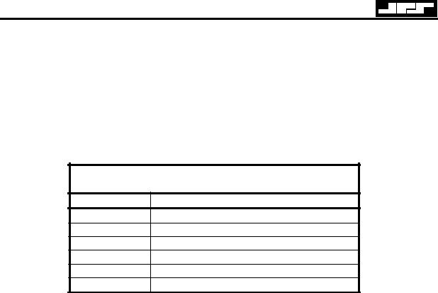
RTU-292 Operations Manual
2.9.1 TELEPHONE CONNECTION
Connect the telephone line to the PHONE J1 RJ11C standard modular connector. The unit will work with either an AC or DC telephone line. Telephone line polarity is not important. Note that the phone connections are repeated at the terminal block on the rear panel for convenience. Only one phone line may be connected; do not use J1 and the telephone connections on the terminal block simultaneously.
Table 2-15 J1 - TEL LINE (RJ-11C)
Pin |
Function |
1Not used
2No Connection
3Telephone Line Connection A
4Telephone Line Connection B
5No Connection
6Not Used
2.9.2RADIO CONNECTION
Connect the radio system to the RADIO J2 connector. The TX output and RX input are designed to interface with 600 Ohm line connections at the radio, but the RTU-292 audio interface is extremely flexible and can accommodate a wide variety of sources and loads. By making different connections, the inputs and outputs may be configured for balanced or unbalanced lines. The balanced configuration is the factory default and should be used if possible, because it is the most noise-immune. To change to the receive audio to unbalanced, single-ended input, connect the receive audio to RXA only and change jumper JP1 on the Main Board to UNBAL. To change to the transmit audio to unbalanced, single-ended output, connect the transmit audio to TXA only and change jumper JP3 on the Main Board to UNBAL. Figures 2-5 and 2-6 details the various audio interface options. P1 pin 4, the External Signal input, is used as the Squelch Break input. Key Out A and Key Out B are normally floating, but pull to ground whenever the RTU-292 wants to key the associated transmitter. The Remote Key Input may be pulled low to force the RTU-292 to key the associated transmitter.
JPS Communications, Inc. |
2-12 |

RTU-292 Operations Manual
Table 2-16 P1-RADIO (DB-9 Male)
Pin |
Function |
1Balanced Receive Audio Input B
2Chassis Ground
3Transmit Audio Output A
4External Signal Input
5/Key Output A (Relay Closure to Ground)
6Receive Audio Input A
7Transmit Audio Output B
8/Remote Key Input
9/Key Output B (Relay Closure to Ground)
2.9.3HANDSET CONNECTOR
The handset supplied with the RTU-292 is plugged into front panel jack J7.
Table 2-17 J7 - HANDSET (RJ12C Jack)
Pin Function
1+5V Source
2Ground
3Ground
4Earpiece Audio
5Mic In
6PTT Switch
2-13 |
JPS Communications, Inc. |
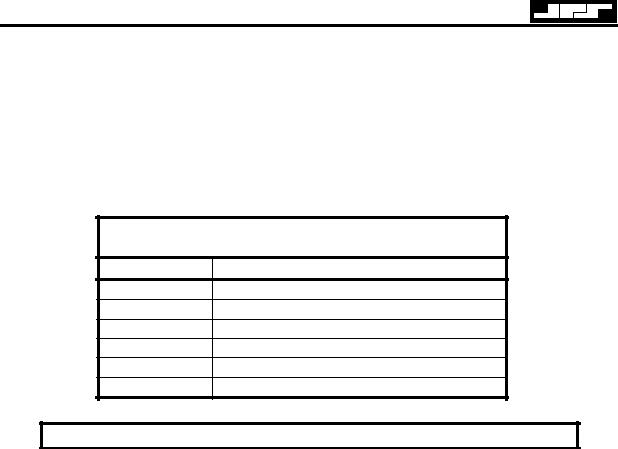
RTU-292 Operations Manual
2.9.4 TERMINAL BLOCK
The terminal block on the rear panel is supplied for convenience when interfacing the RTU-292 to a communications system. The terminal block connections are in parallel with the I/O terminals of the same name found on different connectors. If the telephone line connections at Pin 1 and 2 of the terminal block are used to connect to PSTN line, then the TEL LINE connector, J1, should not be used.
Table 2-18 Terminal Block (6 Position)
Pin Function
1Telephone Line Ring
2Telephone Line Tip
3/Key Out
4/Key In
5Ground
6Spare (See Note Below)
NOTE
In the RTU-282, Pin 6 of the terminal block was the /Squelch In input (also called “External Signal In” for use with the Squelch Break feature. In the RTU-292, this input has been moved to a more appropriate location, pin 4 of the P1 Radio Connector. When retrofitting an RTU-292 into an existing RTU-282 installation, it’s possible to maintain the existing interface wiring, with the /Squelch line connected to pin 6 of the Terminal Block. For this to work, an internal jumper must be added from E1 to E11 on the main PCB. E1 is located just below J12, the connector that interfaces the terminal block to the main PCB. E11 is at the back of the PCB, beneath the terminal block connections.
JPS Communications, Inc. |
2-14 |
Loading...